
Effects of Pd Alloying and Coating on the Galvanic Corrosion between Cu Wire and Bond Pads for a Semiconductor Packaging

1
Materials Research Centre for Energy and Clean Technology, Andong National University, 1375 Gyeongdong-ro, Andong 36729, Republic of Korea
2
School of Materials Science and Engineering, Andong National University, 1375 Gyeongdong-ro, Andong 36729, Republic of Korea
*
Author to whom correspondence should be addressed.
Coatings 2024, 14(5), 544; https://0-doi-org.brum.beds.ac.uk/10.3390/coatings14050544
Submission received: 9 April 2024
/
Revised: 24 April 2024
/
Accepted: 26 April 2024
/
Published: 27 April 2024
(This article belongs to the Special Issue Coatings for Advanced Devices)
Abstract
:Semiconductor chips are packaged in a process that involves creating a path to allow for signals to be exchanged with the outside world and ultimately achieving a form to protect against various external environmental conditions such as heat and moisture. The wire bonding type of packaging is a method in which thin metal wires are bonded to pads to create an electrical connection between the chip and the lead frame. An Epoxy Molding Compound (EMC) can be applied to protect semiconductor chips from external environmental conditions such as heat, shock, and moisture. However, EMC contains halogen elements and sulfides and has hydrophilic properties, which can lead to a corrosive environment. The present study aims to evaluate the influence of chloride, which is a contaminant formed during the PCB manufacturing process. To this end, the galvanic corrosion of bonding wire materials Cu wire, Cu wire alloyed with 1% Pd, and Cu wire coated with Pd was investigated. The first ball bond was bonded to the Al pad and the second stitch bond was bonded to the Au pad of the manufacturing process, after which the galvanic corrosion behavior in the semiconductor packaging module specimen was analyzed. A model of galvanic corrosion behavior was also proposed.
1. Introduction
Semiconductor chips are packaged, which is a process that is intended to create a path by which signals can be exchanged with the outside world and create a form that can protect against various external environmental conditions such as heat and moisture [1]. There are several ways to electrically connect semiconductor chips and substrates, including wire bonding, flip chip bonding, and via silicon [2,3,4]. Among them, wire bonding is a method in which thin metal wires are bonded to pads to create an electrical connection between the chip and the lead frame [5,6]. The metallic types of wires that are mainly used for wire bonding are Au, Ag, Cu, Al, etc., and are typically of fine thickness, which directly affects the efficiency and reliability of semiconductor modules; therefore, it is important to use wires with excellent corrosion resistance and joint degradation characteristics.
In semiconductor packaging, various types of wires are bonded to an Al bond pad to connect them electrically, and then the semiconductor chip is encapsulated to protect it from the external environment. The encapsulation process mainly uses Epoxy Molding Compound (EMC) [7,8]. EMC is widely applied in semiconductor packaging due to its low cost and easy processing, but it inevitably contains ions such as halogen elements (Cl−, Br−, F−) and S [5,9,10,11,12,13], and also has hydrophilic properties that cause it to absorb moisture from the air. As a result, the use of EMC promotes ion diffusion and creates a corrosive environment in the electrolyte [7,12,14,15,16].
Chloride ions are uniformly distributed in the molding compound matrix. To reduce susceptibility to this corrosion, the mold compound contains ion-trapping components that can immobilize the migration of chloride ions; however, packaging processes such as wire bonding and molding can generate chloride ions in localized areas where the temperatures are in excess of the temperature at which chloride is formed, thus causing high concentrations of chloride ions to diffuse through the mold compound [17].
Some packaging processes attempt to avoid corrosion and reliability problems by adjusting the pH to the neutral range and specifying a low ppm range, but chloride ions can also be introduced when using this method [17]. In other words, impurities in the atmosphere include chloride ions, with particles originating from various types and sources. PVC (polyvinyl chloride) materials containing such chloride may decompose at low temperatures below 135 °C, and in some cases even lower temperatures, depending on the additive ingredients, ultimately forming chlorine compounds such as HCl [17]. These Cl− ions can weaken or dissolve the passivation layer in a humid environment, consequently initiating corrosion and narrowing the stable pH range as well as accelerating oxidation, reduction reactions, and the growth of intermetallic compounds, all of which are closely related to the failure mechanism of wire bonds [7,12,18]. In corrosive environments, wires and Al bond pads bonded for electrical connections are subject to galvanic corrosion caused by potential differences [4,7,18,19,20,21].
In the wire bonding process, the wire bond consists of a first bond, which is made on the die bonding pad, and a second bond, which is made on the substrate bonding pad. The first bond is generally formed into a ball shape to provide adhesion and is called a ball bond, while the second bond is called a stitch bond [22]. Both bonds are formed on the PCB substrate, and because stitch bonds are smaller than ball bonds, they are more susceptible to issues related to the plating quality of the pad and surface contamination, which can affect adhesion [22]. The corrosion of Al pads depends on various factors such as halide concentration, pH, corrosion cell characteristics, bimetal contact, temperature, humidity, etc. [12,23,24,25,26]. In Cl− environments in particular, the potential difference of alloys connected in a galvanic couple in the same corrosion environment influences galvanic corrosion behavior, and the corrosion behavior in a corrosion environment in the same galvanic couple was found to be influenced by the anodic and cathodic Tafel constants of the alloys [27]. It has also been reported that the tendency of galvanic corrosion in PCB units is related to the polarization behavior of the anode material in contact with the cathode material [27].
Cu wire has been widely used as an alternative to Au wire in nano-electronics packaging due to its relatively lower cost of raw materials, which in turn can lower overall costs, as well as advantages such as high electrical conductivity and tensile strength, low thermal and electrical resistivity, and improved long-term reliability compared to Au wire bonding, which are attributed to the low reaction rate between Cu and Al [1,6,9,10,11,12,18,28,29,30,31,32]. However, Cu wire requires different process conditions than Au wire, which increases the process cost, and its high hardness makes it difficult to form balls, at the same time requiring the use of high pressures during bonding, which may cause cracks in the pad [6,29]. The Cu wire is also easily oxidized by air due to its low corrosion resistance, so Pd and Au, which are materials with good corrosion resistance, are alloyed or coated on the wire to increase its lifetime and improve the bonding reliability under humid and electrically biased conditions [1,2,5,6,10,29,32,33,34].
In most cases, wire manufacturers use Cu coated with Pd rather than bare Cu. When Cu wire is coated with Pd, it is resistant to oxidation and does not require a forming gas, so it exhibits a greater reliability of secondary bonding [6]. However, its disadvantage is its higher average hardness and melting point than bare Cu, as well as being more expensive [6]. Pd or Au have very good corrosion properties on their own, but when connected to Al or Cu, the risk of galvanic corrosion increases significantly due to the larger potential difference [9,11,16,35].
The Pd coating on Cu wire shows sufficient potential to replace Au wire, as it has excellent bendability and reliability at a relatively low cost [2,6,34,36,37]. The Pd layer on the Cu wire prevents the formation of CuO and protects the bonded ball from corrosion, and stringent molding compound requirements can also be relaxed [6]. The Pd layer on the Cu wire is beneficial to the Cu wire, reducing its corrosion rate due to its electrochemically noble properties, and it improves the failure time in highly accelerated temperature and humidity stress tests (HASTs) [2,33,38].
As reviewed above, various studies have been conducted to examine corrosion phenomena between wire bonding materials that are typically applied in semiconductor packaging, but a systematic approach to managing galvanic corrosion between these materials is lacking. Therefore, the present study evaluates the effects of chloride contaminants formed during the PCB manufacturing process by assessing galvanic corrosion between Cu wire, Cu wire alloyed with 1% Pd, and Cu wire coated with Pd. This is also explored by fabricating a first ball bond on the Al pad and a second stitch bond on an Au pad, to verify galvanic corrosion behavior using a temperature humidity test (THT) in semiconductor packaging module specimens.
2. Materials and Methods
2.1. Test Specimen
Two types of specimens were used in this study: specimens for electrochemical galvanic corrosion between bonding wires and pads, and module specimens that were bonded under semiconductor packaging simulation conditions.
For electrochemical galvanic test specimens: The pads where wire bonding takes place were created by depositing aluminum (Al) onto a 4-inch silicon (Si) wafer using a DC Magnetron Sputterer (KVS-2002L, Korea Vacuum Tech, Kimpo, Korea). For this purpose, a 99.999% pure Al target was used, with deposition conducted under an argon (Ar) gas flow of 20 Standard Cubic Centimeters per Minute (SCCM), a pressure of 1 mTorr, and a power setting of 50 W to achieve a thickness of 605 nm. Then, the sputtered wafer was diced and connected to copper wire using carbon tape for electrochemical testing. All parts of the electrically connected specimen, aside from an area of 0.04 cm2, were insulated using acid-resistant epoxy for the electrochemical tests. Meanwhile, the bonding wire was produced from refined materials with increased purity by excluding impurities, melting, and then alloying to determine the wire type. The alloyed wire is initially formed through continuous casting, processed to reduce its diameter, and finally ready for use after undergoing heat treatment and coiling processes. The bonding wires (Cu, Cu1Pd, and PC wire) used in this study were manufactured by MK Electron Co., Ltd. (Yongin, Gyeonggi-do, Korea), and three wires having the composition presented in Table 1 were used as specimens.
For the temperature humidity test wire bonding module [27]: The wire bonding module consists of a first ball bond and a second stitch bond. Under the conditions listed in Table 2, wire bonding was performed on the bond pads in the FR4 PCB using a wire bonder (K&S RAPID PRO, Kulicke & Soffa, Singapore, Singapore), and the modules were manufactured by MK Electron Co., Ltd. (Yongin, Korea). The first ball bond was bonded with a wire of 25 μm in diameter to a pure Al pad, and the thickness of the Al pad was 10,000~12,000Å. The second stitch bond was bonded with a 25 μm diameter wire to a pure Au pad (the thickness of the Au pad is 0.3 μm). Figure 1 shows a module specimen manufactured as detailed above.
2.2. Polarization Test
A polarization test was conducted to evaluate the corrosion characteristics of the bond pad and bonding wire. To evaluate changes in this behavior under different hydrochloric acid (HCl) concentrations, solutions of 1% NaCl, 1% NaCl + 0.01% HCl, 1% NaCl + 0.1% HCl, and 1% NaCl + 1% HCl were de-aerated with N2 gas at a rate of 200 mL/min for 30 min before the polarization test. The solution temperature was kept at 25 °C. The test equipment used was a Potentiostat (Interface 1000, Gamry, Warminster, PA, USA), in which the reference electrode was a saturated calomel electrode (SCE) and the counter electrode was a platinum electrode. After installing the specimen in the Avesta cell, the corrosion potential was measured after 60 s of conditioning at a potential approximately 200 mV below the corrosion potential, and with an initial delay of 150 s at open-circuit potential, after which the polarization test was performed at a rate of 0.33 mV/s.
2.3. Electrochemical Galvanic Corrosion Test
An electrochemical galvanic corrosion test was conducted to evaluate the galvanic corrosion behavior of the bond pad and bonding wire. In this test, an SCE was used as the reference electrode and a bonding wire was used as the counter electrode. The test solution used was the same 1% NaCl + x% HCl solution used in the polarization test, with the anode to cathode ratio set to 1:1 to exclude any surface. The test equipment used was a Potentiostat (Interface 1000, Gamry, Warminster, PA, USA).
2.4. Temperature Humidity Test (THT)
To evaluate the corrosion properties of the module specimens, a temperature humidity test was performed at a constant temperature and using a humidity chamber (PR-2J, ESPEC, Osaka, Japan). For wire-bonded modules, the test was performed after they were baked at 175 °C for 3 h prior to the test for IMC (intermetallic compound) growth. The module specimen was placed in a chamber by fixing the module specimen to an epoxy substrate and placing it in a glass reaction chamber containing the test solution (the specimen assembly schematic that was followed is described in detail in a previous work [28]). The specimens were placed in the glass cell, which was then placed in the chamber, and the chamber was maintained at 85 °C, 85% R.H. for 100 h. The test solutions were 1% NaCl solution and 1% NaCl + 0.1% HCl solution.
2.5. Surface Analysis
An Optical Microscope (ZEISS, Axiotech 100HD, Oberkochen, Germany) was used to observe the specimen morphology before and after testing, while a 3D microscope (VK-X3000, Keyence, Itasca, IL, USA) was used to observe the overall geometry of the wire connected to the 1st ball bond and the 2nd stitch bond before and after the test. Meanwhile, FE-SEM (FE-SEM, MIRA3XMH, Tescan, Brno, Czech Republic) and EDS (Energy Dispersive X-ray Spectrometer, Mmax 50, Oxford, UK) were used to observe and analyze the morphology of the corroded surfaces and components, respectively.
3. Results and Discussion
3.1. Electrochemical Galvanic Corrosion Behavior of Bonding Wires and Pad Alloys
To evaluate the galvanic corrosion behavior at different HCl concentration, test solutions were prepared by increasing the HCl concentration in a 1% NaCl solution to 0.01%, 0.1%, and 1%. The polarization behavior was then measured in a test solution prepared for every single specimen, and the corrosion rates obtained by Tafel analysis are displayed in Figure 2. Figure 2 shows the effect of HCl concentration on the corrosion rate of sputtered Al and bonding wires as a single specimen in de-aerated 1% NaCl + x% HCl solution at 25 °C. For the Al specimen for the first bond pad, with the increase in HCl concentration, the corrosion rate of sputtered Al tended to decrease and then increase again, but the corrosion rate was very low in the order of μm/y, indicating that the effect of HCl was not significant. According to a previous work by the research team that authored this work [27], it was confirmed that this low corrosion rate can be attributed to the difference in the crystal structure, in which part of the Al becomes amorphous. Meanwhile, the second bond pad materials, Au, Cu wire, Cu1Pd alloy wire, and Pd coated Cu wire, showed a tendency whereby the corrosion rate increased depending on the HCl concentration, but this rate still showed a very small value compared to that observed when using Al.
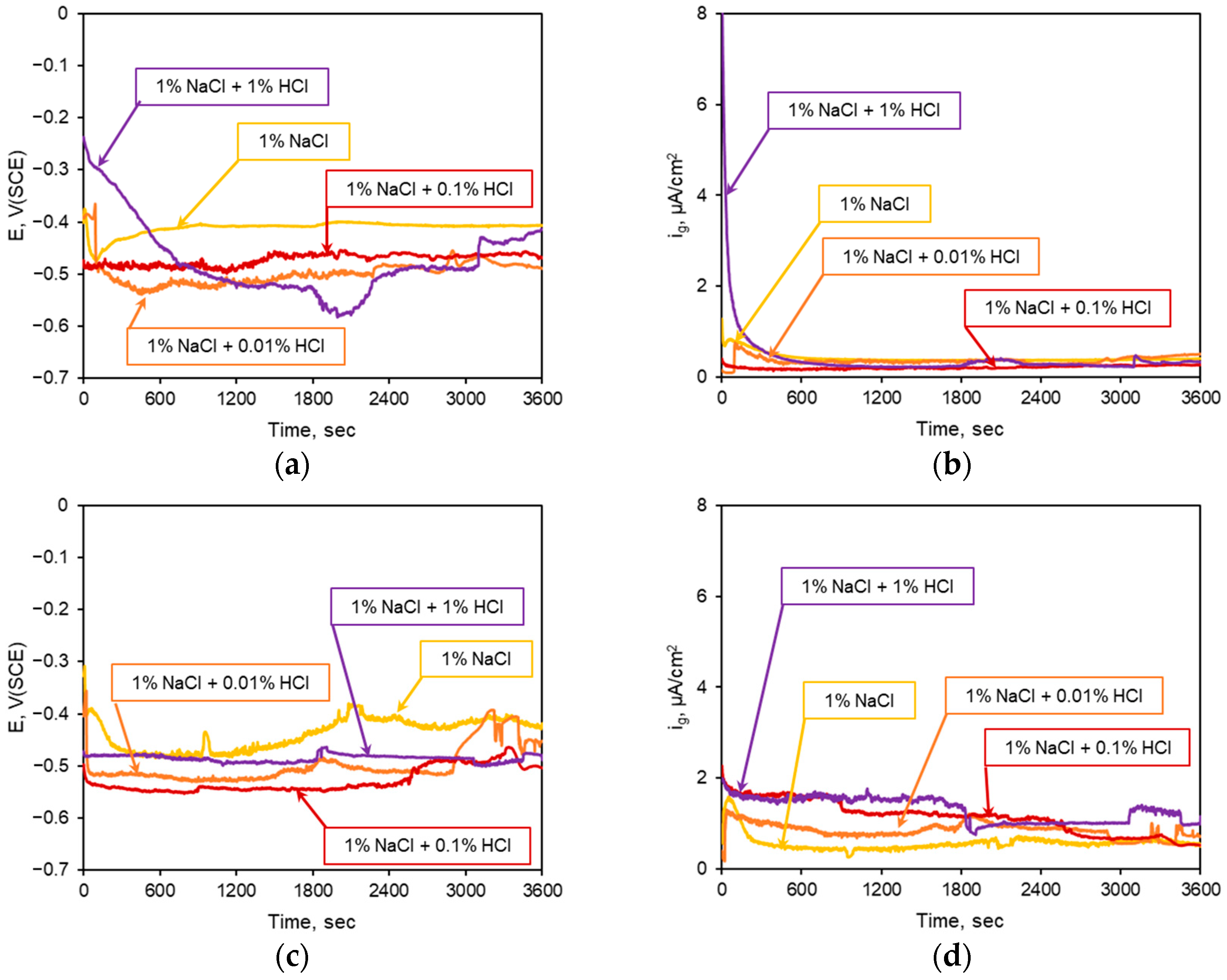
First, to investigate the galvanic corrosion behavior between the sputtered Al and the bonding wire for the first bonding, the effects of Pd alloying and Pd coating on the galvanic corrosion behavior of the Cu-based wire and the Al bond pad when connected in a galvanic couple were examined. The test solution was a 1% NaCl solution with increased HCl concentrations of 0.01%, 0.1%, and 1%. The galvanic corrosion current density and galvanic corrosion potential were measured by connecting the sputtered Al to the working electrode and connecting each wire to the counter electrode. Figure 3 shows the effect of HCl concentration on the electrochemical galvanic corrosion between the bonding wires and the Al bond pad. Figure 3a,b show the galvanic corrosion potential and current density between the Cu wire and the sputtered Al. Increasing the HCl concentration in the 1% NaCl solution increased the galvanic corrosion potential, but did not appear to have a marked effect on the galvanic corrosion current density. Figure 3c,d shows the galvanic corrosion potential and current density between the Cu1Pd wire and the sputtered Al. The results of the galvanic corrosion behavior measured for 1800 s show that the galvanic corrosion current density increased with increasing concentration of HCl. However, no clear concentration effect could be clearly observed, and it was also observed that the galvanic corrosion potential had a slight concentration effect. Figure 3e,f show the galvanic corrosion potential and current density between the PC wire and the sputtered Al. The change in galvanic corrosion potential with increasing HCl concentration was minor, while the galvanic corrosion current density showed an increasing trend with increasing HCl concentration.
The galvanic corrosion rate was calculated based on the galvanic test results depicted in Figure 3, and the resulting corrosion rates are shown in Figure 4. Figure 4 shows the effect of HCl concentration on the galvanic corrosion rate of sputtered Al coupled with Cu wires as measured through electrochemical galvanic corrosion testing. When Cu and Cu1Pd wires and sputtered Al were galvanically coupled, the effect of HCl concentration was small. However, for the galvanic couple of PC wires with sputtered Al, the corrosion rate tended to increase with increasing HCl concentration. This phenomenon is attributed to the fact that the galvanic corrosion rate is further increased by the large potential difference, because the Pd coated on Cu is more noble than Cu itself [1].
Figure 5 shows the surface appearance, documented by optical microscopy (OM), of Al after the electrochemical galvanic corrosion test between sputtered Al and Cu, Cu1Pd and PC wire. It can be seen from the figure that the corrosion of Al accelerated with increasing HCl concentrations. The results show similar trends not only for Cu wire, but also for Pd alloying and coating.
The morphology of the corroded Al surface, where corrosion was accelerated with an increasing HCl concentration, was observed using SEM, and the surface components were analyzed by EDS. Figure 6 shows the effects of the HCl concentration on the surface appearance of Al coupled with Cu wires (SEM) and on the elemental distribution of sputtered Al coupled with Cu wires after the electrochemical galvanic corrosion test. In the case of the Cu wire, as the HCl concentration increased, the Al surface became more and more covered with corrosion products and more cracks were formed. At 1% HCl, the Al corrosion products in the crack area were locally delaminated and the substrate metal was exposed. The results of the EDS surface analysis confirm the course of the corrosion process according to the HCl concentration. Up to the concentration of 1% NaCl + 0.1% HCl, the content of Al increased due to the formation of Al oxide, a corrosion product, on the surface of Al. However, as the concentration of HCl increased, cracks and the delamination of Al oxide occurred, which ultimately exposed the base metal, Si; as a result of this process, the concentration of Si increased and the concentration of Al decreased. In the case of Cu1Pd wire, the surface image obtained by SEM and the average value from the surface analysis show that, as the concentration of HCl increased, the corrosion products formed on the surface increased, and the content of Al decreased due to the dissolution of Al, as a result of which Si, a base metal, was exposed. For the PC wire and sputtered Al connected via galvanic coupling, the corrosion morphology of Al as a function of HCl concentration was analyzed by SEM-EDS, and the results show that the dissolution of Al accelerated with increasing HCl concentrations. It can be seen that, at a concentration of 1% HCl, all the Al was dissolved, and Si and Si oxide were formed on the surface.
To analyze the galvanic corrosion behavior detailed above, an electrochemical analysis was conducted using mixed potential theory [1]. Figure 7 shows the analysis of galvanic corrosion using the mixed potential theory between sputtered Al specimen and Cu wires. From the polarization curves of two alloys intersecting in the galvanic couple, various electrochemical parameters can be obtained, including the corrosion potential difference (ΔE), the galvanic corrosion potential (Eg) and the corrosion current density according to the mixing potential theory, the anodic reaction Tafel constant (βA), and the cathodic reaction Tafel constant (βC).
The sputtered Al pad, which is connected to three types of Cu wires in the galvanic couple, has a relatively active potential, so it can serve as an anode. As the cathodic polarization curves of the three types of Cu wires meet in the trans-passive region of the anodic polarization curve of sputtered Al, the corrosion of Al becomes accelerated. Moreover, as the concentration of HCl increases, the galvanic current density at which each polarization curve intersects tends to increase, indicating that as the corrosivity of the test solution increases, the galvanic corrosion rate also increases. In the case of the Cu1Pd wire, we aimed to improve the corrosion resistance of Cu by alloying with Pd, a metal with good corrosion resistance, but alloying in a small amount of 1% causes a cathodic polarization behavior similar to that of pure Cu wire. The electrochemical galvanic corrosion behavior of Cu1Pd wire with an Al pad is also similar to that of Cu wire. On the other hand, in the case of the Pd-coated PC wire, the corrosion potential increases slightly in the 1% NaCl solution due to the noble Pd, and the cathodic polarization behavior is similar to that of the Cu wire. However, as the corrosivity of the test solution increases, the coated Pd in the thin film also dissolves, and galvanic corrosion with Cu increases, increasing the current density due to cathodic polarization. For this reason, it can be seen that the corrosion rate increases as a result of the galvanic corrosion of the PC wire and Al pad.
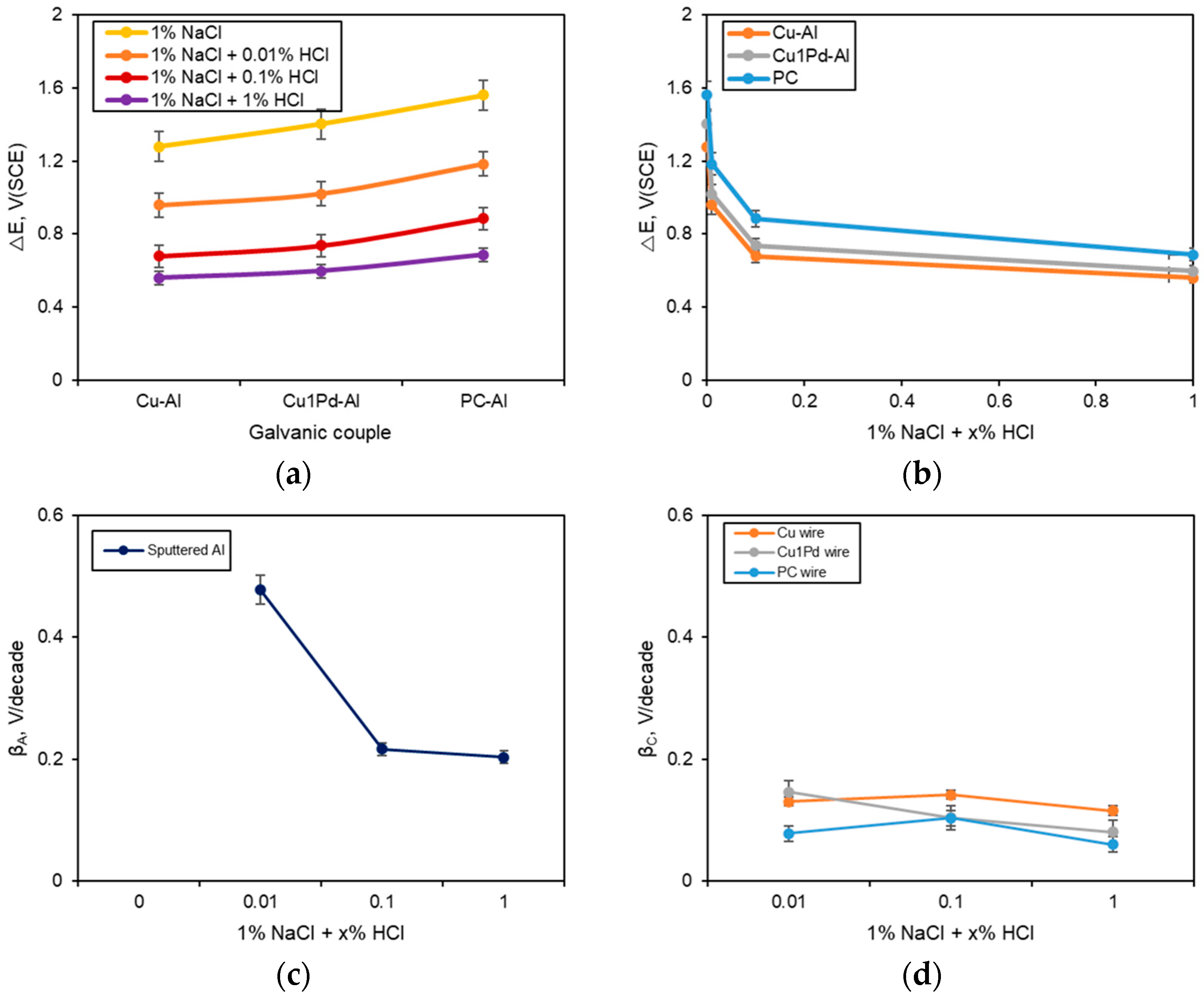
The galvanic corrosion behavior was analyzed by various electrochemical parameters obtained from the polarization behavior of each alloy, and the results are shown in Figure 8. In particular, Figure 8a,b show the effects of Pd alloying and Pd coating on the galvanic potential difference (ΔE) when the three types of wires and Al bond pads are galvanically connected. In other words, when a Pd alloying or Pd coating was applied to the Cu wire connected to Al in a galvanic couple, the galvanic potential difference increased regardless of the HCl concentration. In general, in the same environment, the galvanic potential difference is highly correlated with the galvanic corrosion rate, since the galvanic corrosion rate increases as the galvanic potential difference increases (Figure 8a).
However, as shown in Figure 8b, the galvanic potential difference decreased with increasing HCl concentration, which shows the difficulty associated with explaining the effect of HCl concentration on the intermetallic galvanic potential difference in the same material. To analyze this behavior, the anode and cathode Tafel constants were compared as a function of HCl concentration. Figure 8c,d shows the anodic Tafel constant and cathodic Tafel constant depending on the HCl concentration. For sputtered Al, the anodic Tafel constant decreased with increasing HCl concentration when the bonding wires and bonding pads were connected via galvanic coupling. The cathodic Tafel constant of the wires was also generally reduced. According to the latest model reporting the effects of HCl concentration on galvanically coupled Au and Cu wires and sputtered Al [27], for the same material, changing the Tafel constant of each galvanic coupled affects the galvanic corrosion rate when the corrosion environment changes. Therefore, in the case of the Cu1Pd-Al galvanic couple in this study, the anodic Tafel constant of Al and the cathodic Tafel constant of the wire decreased with the increase in HCl concentration. Meanwhile, in the case of the PC-Al galvanic couple, the anodic Tafel constant of Al decreased and the cathodic Tafel constants of the wire decreased with increasing HCl concentrations. In other words, as shown in Figure 4, the effects of HCl concentration on the galvanic corrosion of Al pads and three types of wires can be interpreted based on a combined consideration of the anodic and cathodic Tafel constants.
3.2. Galvanic Corrosion Behavior of the Wire Bonding Module by THT
Meanwhile, to observe the galvanic corrosion behavior at the interface of the wire bonded to the PCB bonding pad, THT was conducted for 100 h at 85 °C and 85% using a wire bonding module. The test solutions were 1% NaCl and 1% NaCl + 0.1% HCl, and the surface morphology and elemental distribution of the first ball bonding part and second stitch bonding part were analyzed after the test. Figure 9 shows the surface appearance of the wire bonding module before and after THT at 85 °C and 85% relative humidity for 100 h. Before testing, there were no signs of corrosion, and it could be seen that both the first ball bonding, which is made of a square die-shaped pure Al pad, and the second stitch bonding area, which is bonded to the pure Au substrate by pressing, maintained their integrity (Figure 9a). Meanwhile, after THT, it can be seen that the wire, bond pad, and bonding area were severely corroded, regardless of the wire type (Figure 9b–d). In the first ball bonding area, corrosion progress could be seen in the Al bonding pad area, while in the second stitch bonding area with the Au substrate, where most of the Au maintained its integrity, it could be seen that the bonding area and wire were corroded. In particular, as shown in Figure 9d, it can be seen that the PC wire module is covered with corrosion products over a wide area.
For each module, the surface morphology and elemental distribution of the first ball bonding area and the second stitch bonding area were confirmed by SEM-EDS. Figure 10 shows the SEM images and elemental distribution of the first bond area with wires and the Al pad on the module after temperature–humidity tests at 85 °C, 85% RH in 1% NaCl. In the first ball bond area between Cu wire and Al pad, when a THT was conducted in a 1% NaCl solution for 100 h, it could be seen that the Al pad near the ball was corroded and corrosion products were formed, and it could also be observed that the bonded Cu ball also formed corrosion products. A similar tendency was observed in the first ball bond area of the Cu1Pd wire and the PC wire module. Most corrosion products were formed on the Al pad, and as the amount of corrosion products increased, they were increasingly located in the ball area. These corrosion products were mainly composed of Al oxide, and Al, which has a relatively active potential, is preferentially corroded by the galvanic effect, which is consistent with the electrochemical galvanic corrosion behavior observed herein. Cu wires were also found to be partially corroded due to their low resistance in highly corrosive environments, leading to the formation of Cu oxide corrosion products on the surface.
Figure 11 shows the SEM images and elemental distribution of the first bond area with wires and the Al pad on the module after THT at 85 °C, 85% RH in 1% NaCl + 0.1% HCl. When the Cu wire, Cu1Pd wire, and PC wire were exposed to the test solution for 100 h at the first ball bond between the Cu wire, Cu1Pd wire, PC wire, and Al pad, the Al pad near the ball was corroded and the Al oxide was corroded. The resulting corrosion products became attached to the bonded wire balls. It was also confirmed that, as the severity of the corrosive environment increased, Cu, the main component of the wire, dissolved and formed corrosion products in the form of Cu oxide.
In the case of the PC wire, the Pd coated on the surface can be clearly detected in the component distribution after THT in a 1% NaCl environment (Figure 10, third row). However, in the component distribution results after THT in a 1% NaCl + 0.1% HCl environment (Figure 11, third row), the very thin Pd coating layer is not clearly revealed, and it is more difficult to detect because it is also corroded due to the strong corrosive environment. Ultimately, the results indicate that Cu oxide forms together with Al oxide on the Al pad, ball bond area, and wire surface.
It can be seen that the galvanic corrosion behavior in these packing modules is consistent with the electrochemical galvanic corrosion results. In the wire bonding module, when the Al pad and the first ball bonded wire are exposed to the corrosive environment, galvanic corrosion occurs, which accelerates the corrosion of the relatively active Al pad. However, when a highly corrosive environment is formed, the wire also corrodes, as shown in Figure 3 and Figure 7.
When the Au pad and wire are exposed to a corrosive environment, the corrosion of Au, which is a more noble metal than the wire, is suppressed, and the wire material acts as an anode, thus causing galvanic corrosion that accelerates the corrosion in general. Figure 12 shows the SEM images and elemental distribution of the second stitch bond area with wires and the Al pad on the module before the test. The wires pressed into the Au pad do not have any oxides formed on them, and there are no signs of corrosion. In the case of the Cu1Pd wire, 1% of the Pd was alloyed, so the Pd component was not clearly visible, while in the case of the PC wire, only Cu was present in the compressed area, and the Pd component was detected due to the Pd coating on the surface of the wire.
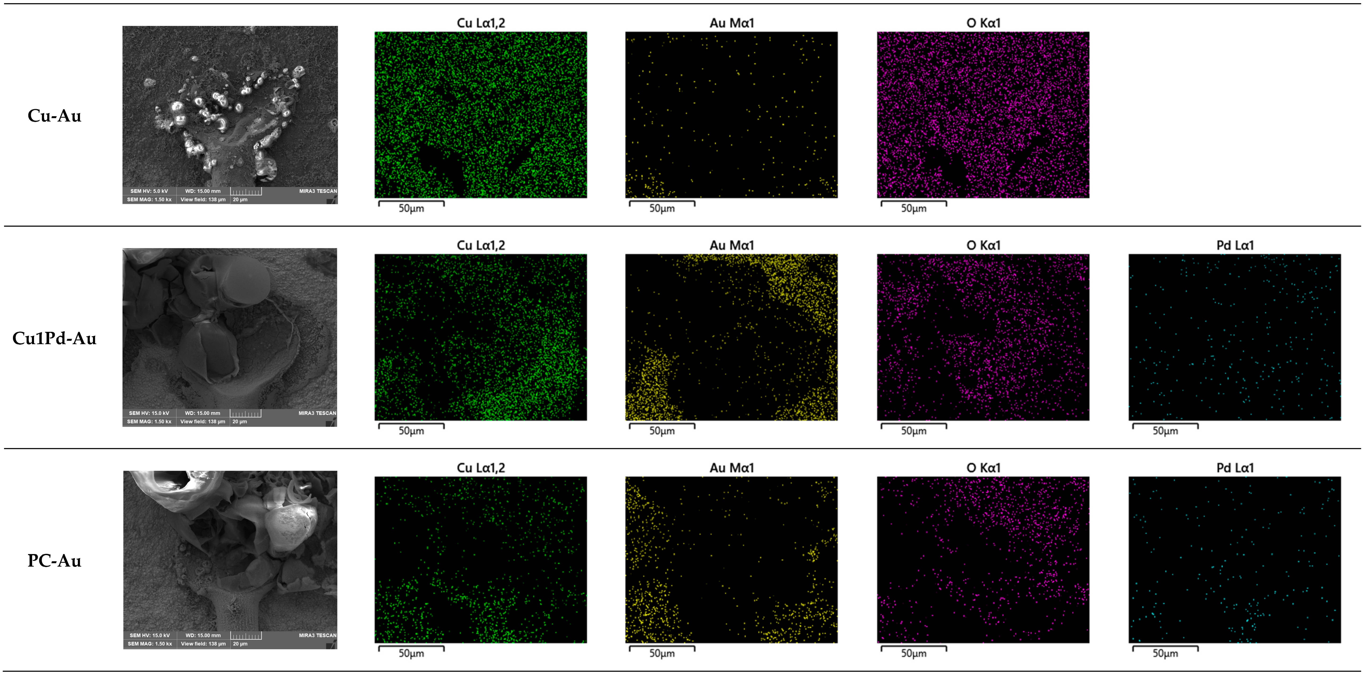
Figure 13 shows the SEM images and elemental distribution of the second stitch bond area with wires and the Au pad on the module after the temperature–humidity test at 85 °C, 85% RH in 1% NaCl. The surface morphology of the second bond area of the Cu wire and Au pad shows that the corrosion of the Cu wire progresses with the formation of corrosion products covering the surface of the Au pad. In the case of the Cu1Pd wire, no corrosion products were formed under the influence of 1% NaCl solution for 100 h, unlike in the case of the Cu wire. However, it was confirmed that Cu oxide was partially distributed on the surface of the Au pad due to the dissolution of the Cu wire. On the other hand, in the case of the PC wire, it was observed that more corrosion products were formed and covered on the Au pad than in the case of the Cu wire. When the environment became more corrosive after adding HCl, the corrosion of the second stitch bond area was also accelerated.
Figure 14 shows the SEM images and the elemental distribution of the second stitch bond area with wires and the Au pad on the module after the temperature–humidity test at 85 °C, 85% RH in 1% NaCl + 0.1% HCl. In the case of the Cu wire, the formation of corrosion products could be observed, which spread to the surface of the Au pad, thereby covering the Au surface. More corrosion products were formed than in the 1% NaCl environment, and the results also showed a trend whereby, as the intensity of the corrosion environment increased, the amount of corrosion products also increased. The Cu1Pd wire also showed a similar trend to the Cu wire. However, the PC wire showed the most severe corrosion behavior, as occurred in the 1% NaCl environment. This result is attributed to the fact that the Pd covering the surface is a nobler metal than Cu, so the exposed area of Cu acting as an anode via stitch bonding is small, and the area of Au and Pd acting as cathodes increases, ultimately resulting in a larger galvanic effect.
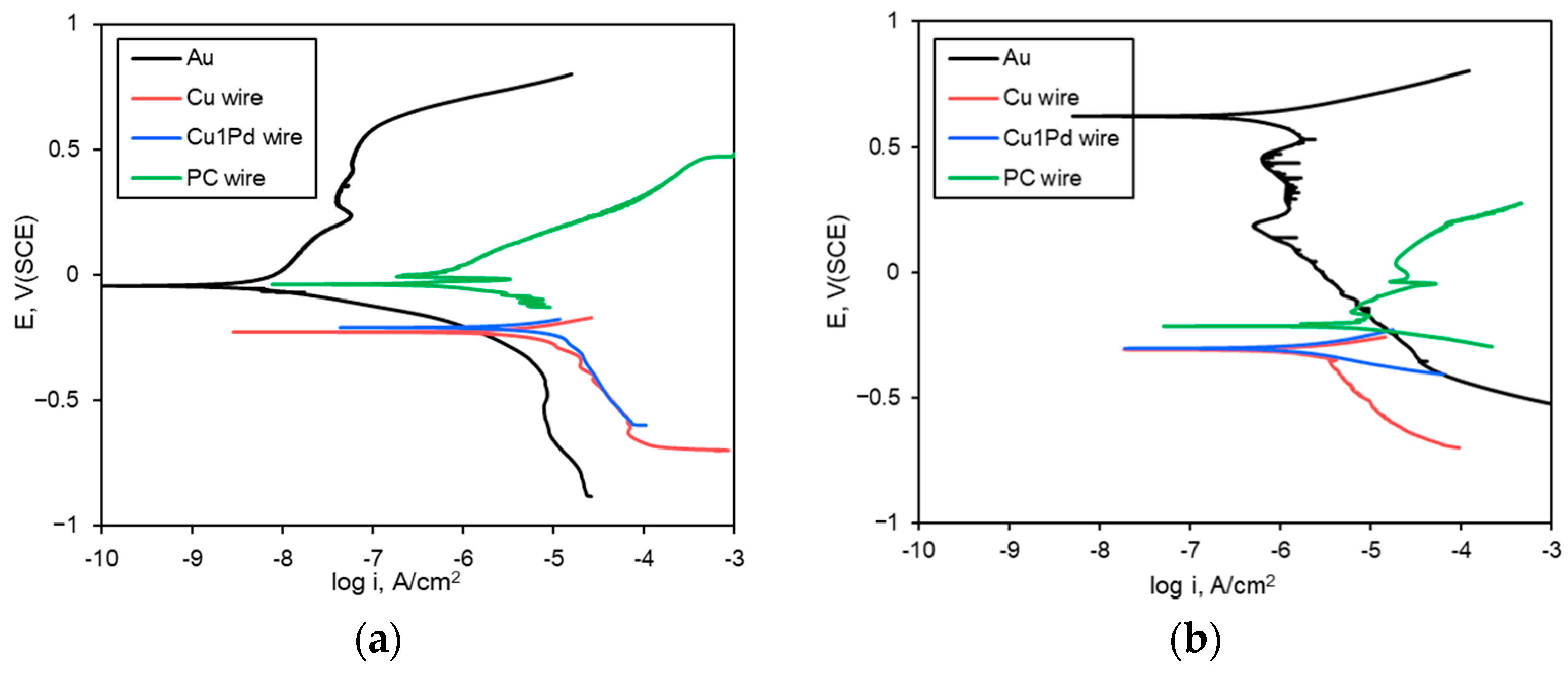
As detailed above, the galvanic corrosion behavior occurring in the second stitch bonding of the packaging module was analyzed using mixed potential theory. Figure 15 shows the analysis of galvanic corrosion behavior using mixed potential theory between the Au specimen and Cu wires. Figure 15a shows a graph comparing the polarization behavior of Au and Cu wires in a 1% NaCl solution. The corrosion potential of Au is higher than that of other examined wires other than PC wire, which means that, when Au- and Cu-based wires are connected into a galvanic couple, the wire works as an anode, and galvanic corrosion occurs. On the other hand, in the case of Pd-coated PC wire, the wire material exposed to the initial corrosive environment becomes Pd, a noble material, and thus exhibits a corrosion potential similar to Au. However, there is a difference of about two orders of magnitude in the current density, so it can be said that the Cu substrate also affects the corrosion rate. Therefore, for the second stitch bonding area where the PC wires are bonded, the Cu is exposed at the part pressed by bonding, and then the accelerated galvanic corrosion is caused by the Au bond pad and Pd coating layer. As the intensity of the corrosive environment increases, it becomes easier for Cu to be exposed, as it is less protected by the thin Pd layer. As can be seen in Figure 15b, galvanic corrosion is accelerated when the anodic polarization behaviors of all wires interact with the cathodic polarization behavior of Au. Figure 16 show the effect of HCl concentration on the galvanic corrosion rate of Au coupled with Cu wires according to the mixed potential theory. According to the mixed potential theory, when Cu, Cu1Pd, and PC wire are coupled with Au in a galvanic couple, it is observed that the galvanic corrosion rate increases with an increase in HCl concentration. It is confirmed that the galvanic corrosion rate by the mixed potential theory is closely consistent with the electrochemical galvanic corrosion behavior.
In semiconductor devices, galvanic corrosion between the bonding wires and bonding pads can significantly impact device reliability and performance over time. Initially, this may not have a significant effect on the device’s performance, but exposure to electrolytes can trigger electrochemical reactions between the bonding wire and the pad. The resulting corrosion products increase the contact resistance, impeding the current flow and leading to power losses. As galvanic corrosion progresses, the physical bond may weaken, which can lead to micro-contact separation and circuit shorts or breaks. This degradation escalates device malfunction and failure rates, ultimately reducing device reliability.
If galvanic corrosion intensifies, it can sever electrical connections, leading to total device failure, with severe consequences such as data loss or system breakdowns. Galvanic corrosion can occur rapidly or develop slowly over an extended period. Therefore, factors such as environmental control, material selection, and surface treatments that prevent corrosion are critical considerations in the semiconductor manufacturing process.
The results and discussion presented above make it possible to propose the following galvanic corrosion mechanism between the bond pads and the wires (Figure 17): In the first ball bond area, corrosion occurs on the Al pad, which has a relatively active potential compared to the wires due to the galvanic effect, and Al oxide covers the pad and wire surroundings. However, the severe corrosive environment also causes the local corrosion of Cu, Cu1Pd, and PC wires. Meanwhile, in the second stitch bond area, galvanic corrosion occurs due to the relatively active potential of the wires compared to the Au pad, which preferentially corrodes the wire. The Cu and Cu1Pd wire dissolve and form an oxide covering the Au pad. Meanwhile, in the case of Pd-coated PC wire, Cu is only exposed to the pressed part, and the area of Cu acting as an anode becomes small due to the presence of the noble metal Pd on the wire surface. In this case, galvanic corrosion is further accelerated by the area effect of the small anode combined with the large cathode effect.
4. Conclusions
In this study, to evaluate the influence of chloride, which is a contaminant formed during the PCB manufacturing process, the galvanic corrosion of bonding wire materials Cu wire, Cu wire alloyed with 1% Pd, and Pd-coated Cu wire was evaluated. The first ball bond was bonded to the Al pad and the second stitch bond was bonded to the Au pad in the preparation process, and the galvanic corrosion behavior of the semiconductor packaging module specimen was analyzed, resulting in the following conclusions;
1. In the first ball bonding area between the Al pad and the wires, the Al pad, which is a relatively active metal compared to the wires, undergoes preferential corrosion. For the same materials, galvanic corrosion between the Al pad and the three types of wires in terms of HCl concentration shows a high correlation with the anodic and cathodic Tafel constants;
2. In the second stitch bonding area between the Au pad and the wires, for the Cu and Cu1Pd wires, corrosion occurs in the wire because the Au pad has a relatively noble potential, while the formed Cu oxide is overlaid on the surface of the Au pad. On the other hand, in the Pd-coated PC wire, Cu is only exposed in the pressed area between the wire and the Au pad, and the galvanic corrosion is accelerated due to the small anode–large cathode effect because of the noble potential of the coated Pd and Au pad.
Author Contributions
Conceptualization, Y.-R.Y.; methodology, Y.-R.Y.; validation, Y.-R.Y.; formal analysis, Y.-S.K.; investigation, Y.-R.Y.; resources, Y.-S.K.; data curation, Y.-R.Y.; writing—original draft preparation, Y.-R.Y.; writing—review and editing, Y.-S.K.; visualization, Y.-R.Y.; supervision, Y.-S.K.; project administration, Y.-R.Y. and Y.-S.K.; funding acquisition, Y.-S.K. All authors have read and agreed to the published version of the manuscript.
Funding
This research was supported by a grant from the 2023–2024 research funds of Andong National University, and the Korea Institute for Advancement of Technology (KIAT) grant funded by the Korea Government (MOTIE) (HRD Program for Industrial Innovation).
Institutional Review Board Statement
Not applicable.
Informed Consent Statement
Not applicable.
Data Availability Statement
Data are contained within the article.
Acknowledgments
The authors would like to thank MK electron Co., Ltd., for supplying the materials.
Conflicts of Interest
The authors declare no conflicts of interest.
References
- Cheng, P.Y.; Lai, P.Y.; Ye, Z.J.; Hsieh, C.L.; Ye, J.M. Effect of Pd distribution on Pd-plated Cu wire using different electronic flame off settings. J. Mater. Sci. Mater. Electron. 2017, 28, 4613–4618. [Google Scholar] [CrossRef]
- Uno, T. Bond reliability under humid environment for coated copper wire and bare copper wire. Microelectron. Reliab. 2011, 51, 148–156. [Google Scholar] [CrossRef]
- Qin, I.; Yauw, O.; Schulze, G.; Shah, A.; Chylak, B.; Wong, N. Advances in Wire Bonding Technology for 3D Die Stacking and Fan Out Wafer Level Package. In Proceedings of the 2017 IEEE 67th Electronic Components and Technology Conference (ECTC), Orlando, FL, USA, 30 May–2 June 2017. [Google Scholar] [CrossRef]
- Qin, W.; Anderson, H.; Anderson, T.; Chang, G.D. Corrosion Mechanisms of Cu Wire Bonding on Al Pads. In Proceedings of the 2018 IEEE 68th Electronic Components and Technology Conference (ECTC), San Diego, CA, USA, 29 May–1 June 2018. [Google Scholar] [CrossRef]
- Wu, Y.; Barton, S.C.; Lee, A. Galvanic corrosion behavior at the Cu-Al ball bond interface: Influence of Pd addition and chloride concentration. Microelectron. Reliab. 2019, 92, 79–86. [Google Scholar] [CrossRef]
- Chauhan, P.; Zhong, Z.W.; Pecht, M. Copper Wire Bonding Concerns and Best Practices. J. Electron. Mater. 2013, 42, 2415–2434. [Google Scholar] [CrossRef]
- Soestbergen, M.V.; Mavinkurve, A.; Zaal, J.J.M.; O‘Halloran, G.M.; Rongen, R.T.H.; Farrugia, M.L. Crevice Corrosion of Ball Bond Intermetallics of Cu and Ag Wire. In Proceedings of the 2016 IEEE 66th Electronic Components and Technology Conference (ECTC), Las Vegas, NV, USA, 31 May–3 June 2016. [Google Scholar] [CrossRef]
- Kumar, G.I.A.; Alptekin, J.; Caperton, J.; Salunke, A.; Chyan, O. Accelerated reliability testing of Cu-Al bimetallic contact by a micropattern corrosion testing platform for wire bond device application. MethodsX 2021, 8, 101320. [Google Scholar] [CrossRef]
- Ross, N.; Asokan, M.; Kumar, G.I.A.; Caperton, J.; Alptekin, J.; Salunke, A.S.; Chyan, O.M. Mechanistic study of copper wire-bonding failures on packaging devices in acidic chloride environments. Microelectron. Reliab. 2020, 113, 113917. [Google Scholar] [CrossRef]
- Fu, S.W.; Lee, C.C. A corrosion study of Ag-Al intermetallic compounds in chlorine-containing epoxy molding compounds. J. Mater. Sci. Mater. Electron. 2017, 28, 15739–15747. [Google Scholar] [CrossRef]
- Ly, N.; Xu, D.E.; Song, W.H.; Mayer, M. More uniform Pd distribution in free-air balls of Pd-coated Cu bonding wire using movable flame-off electrode. Microelectron. Reliab. 2015, 55, 201–206. [Google Scholar] [CrossRef]
- Kumar, G.I.A.; Lamber, A.; Caperton, J.; Asokan, M.; Yi, W.; Chyan, O. Comparative Study of Chloride and Fluoride Induced Aluminum Pad Corrosion in Wire-Bonded Device Packaging Assembly. Corros. Mater. Degrad. 2021, 2, 447–460. [Google Scholar] [CrossRef]
- Chiu, Y.T.; Chiang, T.H.; Chen, Y.F.; Yang, P.F.; Huang, L.; Lin, K.L. The Corrosion Performance of Cu Alloy Wire Bond on Al Pad in Molding Compounds of Various Chlorine Contents under Biased-HAST. In Proceedings of the 2014 IEEE 64th Electronic Components and Technology Conference (ECTC), Lake Buena Vista, FL, USA, 27–30 May 2014. [Google Scholar] [CrossRef]
- Soestbergen, M.V.; Ernst, L.J.; Zhang, G.Q.; Rongen, R.T.H. Transport of Corrosive Constituents in Epoxy Molding Compounds. In Proceedings of the 2007 International Conference on Thermal, Mechanical and Multi-Physics Simulation Experiments in Microelectronics and Micro-Systems. EuroSime 2007, London, UK, 15–18 April 2007. [Google Scholar] [CrossRef]
- Tai, C.T.; Lim, H.Y.; Teo, C.H.; Audrey Swee, P.J. An investigation on Cu Wire Bond Corrosion and Mitigation Technique for Automotive Reliability. In Proceedings of the 2012 35th IEEE/CPMT International Electronics Manufacturing Technology Conference (IEMT), Ipoh, Malaysia, 6–8 November 2012. [Google Scholar] [CrossRef]
- Kim, H.J.; Lee, J.Y.; Paik, K.W.; Koh, K.W.; Won, J.H.; Choe, S.H.; Lee, J.; Monn, J.T.; Park, Y.J. Effects of Cu/Al Intermetallic Compound (IMC) on Copper Wire and Aluminum Pad Bondability. IEEE Trans. Compon. Packag. Technol. 2003, 26, 367–374. [Google Scholar] [CrossRef]
- Mathew, V.; Wikramanayake, E.; Chopin, S.F. Corrosion of Copper Wire bonded Packages by Chlorine Containing Foreign Particles. In Proceedings of the 2020 IEEE 70th Electronic Components and Technology Conference (ECTC), Orlando, FL, USA, 3–30 June 2020. [Google Scholar] [CrossRef]
- Goh, C.S.; Chong, W.L.E.; Lee, T.K.; Breach, C. Corrosion Study and Intermetallics Formation in Gold and Copper Wire Bonding in Microelectronics Packaging. Crystals 2013, 3, 391–404. [Google Scholar] [CrossRef]
- Liu, D.; Chen, H.; Wu, J.; Then, E. Corrosion Behavior of Cu-Al Intermetallic Compounds in Copper Wire Bonding in Chloride Containing Accelerated Humidity Testing. In Proceedings of the 2016 IEEE 66th Electronic Components and Technology Conference (ECTC), Las Vegas, NV, USA, 31 May–3 June 2016; pp. 629–636. [Google Scholar]
- Yang, Y.; Zhu, X.; Nistala, R.R.; Zhao, S.; Xu, J. A method to simulate fluorine outgas and Al bond pad corrosion in wafer fab. In Proceedings of the 2016 IEEE 23rd International Symposium on the Physical and Failure Analysis of Integrated Circuits (IPFA), Singapore, 18–21 July 2016. [Google Scholar] [CrossRef]
- Younan, H.; Xiang, X.Z.; Xiaomin, L. Characterization studies of fluorine-induced corrosion crystal defects on microchip Al bondpads using X-ray photoelectron spectroscopy. In Proceedings of the 2014 IEEE 21th International Symposium on the Physical and Failure Analysis of Integrated Circuits (IPFA), Singapore, 30 June–4 July 2014. [Google Scholar] [CrossRef]
- Fu, C.H.; Hung, L.Y.; Jiang, D.S.; Chang, C.C.; Wang, Y.P.; Hsiao, C.S. Evaluation of new substrate surface finish: Electroless nickel/electroless palladium/immersion gold (ENEPIG). In Proceedings of the 2008 58th Electronic Components and Technology Conference, Lake Buena Vista, FL, USA, 27–30 May 2008. [Google Scholar] [CrossRef]
- Zeng, Y.; Bai, K.; Jin, H. Thermodynamic study on the corrosion mechanism of copper wire bonding. Microelectron. Reliab. 2013, 53, 985–1001. [Google Scholar] [CrossRef]
- Farrah, H.; Slavek, J.; Pickering, W. Fluoride interactions with hydrous aluminum oxides and alumina. Soil Res. 1987, 25, 55–69. [Google Scholar] [CrossRef]
- Proost, J.; Baklanov, M.; Verbeeck, R.; Maex, K. Morphology of corrosion pits in aluminum thin film metallizations. J. Solid State Electrochem. 1998, 2, 150–155. [Google Scholar] [CrossRef]
- Loto, R.T. Investigation of the Localized Corrosion Resistance of 4044 Aluminum Alloy in Acid Chloride and Neutral Chloride Solutions. J. Fail. Anal. Prev. 2018, 18, 905–911. [Google Scholar] [CrossRef]
- Yoo, Y.-R.; Kim, G.; Jeon, S.-M.; Park, H.-J.; Seo, W.-W.; Moon, J.-T.; Kim, Y.-S. Influence of HCl Concentration on Corrosion Behavior between Au or Cu Bonding Wires and the Bond Pad for Semiconductor Packaging. Materials 2023, 16, 7275. [Google Scholar] [CrossRef] [PubMed]
- Zhong, Z.W. Wire bonding using copper wire. Microelectron. Int. 2009, 26, 10–16. [Google Scholar] [CrossRef]
- Lee, T.K.; Breach, C.D.; Chong, W.L.; Goh, C.S. Oxidation and corrosion of Au/Al and Cu/Al in wire bonding assembly, 2012. In Proceedings of the 13th International Conference on Electronic Packaging Technology & High Density Packaging, Guilin, China, 13–16 August 2012. [Google Scholar] [CrossRef]
- Gan, C.L.; Ng, E.K.; Chan, B.L.; Hashim, U.; Classe, F.C. Technical Barriers and Development of Cu Wirebonding in Nanoelectronics Device Packaging. J. Nanomater. 2012, 2012, 173025. [Google Scholar] [CrossRef]
- Hong, W.S.; Kim, M.-R.; Kim, S.Y.; Jeon, S.M.; Moon, J.T.; Kim, Y.-S. Corrosion characteristics of Gold-Coated Silver Wire for Semiconductor Packaging. Corros. Sci. Technol. 2021, 20, 289–294. [Google Scholar] [CrossRef]
- Lim, A.B.Y.; Chang, A.C.K.; Yauw, O.; Chylak, B.; Gan, C.L.; Chen, Z. Ultra-fine pitch palladium-coated copper wire bonding: Effect of bonding parameters. Microelectron. Reliab. 2014, 54, 2555–2563. [Google Scholar] [CrossRef]
- Wu, Y.; Subramanian, K.N.; Barton, S.C.; Lee, A. Electrochemical studies of Pd-doped Cu and Pd-doped Cu-Al intermetallics for understanding corrosion behavior in wire-bonding packages. Microelectron. Reliab. 2017, 78, 355–361. [Google Scholar] [CrossRef]
- Lau, K.T.; Cha, C.L. A Review of Palladium Coated Copper Wire Bonding For Automotive Device. Int. J. Mech. Prod. Eng. Res. Dev. 2020, 10, 4479–4492. [Google Scholar]
- Fontana, M.G. Corrosion Engineering, 3rd ed.; 1 International Business Park #01-15A; MCGraw-Hill Book company: Singapore, 1985; pp. 41–51, 463–468. [Google Scholar]
- Kaimori, S.; Nonaka, T.; Mizoguchi, A. The development of Cu bonding wire with oxidation-resistant metal coating. IEEE Trans. Adv. Packag. 2006, 29, 227–231. [Google Scholar] [CrossRef]
- Singh, I.; Qin, I.; Xu, H.; Huynh, C.; Low, S.; Clauberg, H.; Chylak, B.; Acoff, V.L. Pd-coated Cu wire bonding technology: Chip design, process optimization, production qualification and reliability test for high reliability semiconductor devices. In Proceedings of the 2012 IEEE 62nd Electronic Components and Technology Conference, San Diego, CA, USA, 29 May–1 June 2012. [Google Scholar] [CrossRef]
- Leong, G.C.; Uda, H. Comparative reliability studies and analysis of Au, Pd-coated Cu and Pd-doped Cu wire in microelectronics packaging. PLoS ONE 2013, 8, e78705. [Google Scholar] [CrossRef] [PubMed]
Figure 1.
Module specimen containing 1st ball bond and 2nd stitch bond manufactured by MK electron Co., Ltd.
Figure 1.
Module specimen containing 1st ball bond and 2nd stitch bond manufactured by MK electron Co., Ltd.

Figure 2.
Effect of HCl concentration on the corrosion rate of sputtered Al and bonding wires as a single specimen in de-aerated 1% NaCl + x% HCl solution at 25 °C.
Figure 2.
Effect of HCl concentration on the corrosion rate of sputtered Al and bonding wires as a single specimen in de-aerated 1% NaCl + x% HCl solution at 25 °C.

Figure 3.
Effect of HCl concentration on the electrochemical galvanic corrosion between the bonding wires and the Al bond pad: (a) Galvanic corrosion potential of Cu-Al [27] and (b) Galvanic current density of Cu-Al. (c) Cu1Pd-Al galvanic corrosion potential and (d) Cu1Pd-Al Galvanic current density. (e) PC-Al galvanic corrosion potential and (f) PC-Al galvanic current density.


Figure 4.
Effect of HCl concentration on the galvanic corrosion rate of sputtered Al coupled with Cu wires, as measured by the electrochemical galvanic corrosion test.
Figure 4.
Effect of HCl concentration on the galvanic corrosion rate of sputtered Al coupled with Cu wires, as measured by the electrochemical galvanic corrosion test.

Figure 5.
Effect of HCl concentration on the surface appearance of Al coupled with Cu wires (OM) [27].
Figure 5.
Effect of HCl concentration on the surface appearance of Al coupled with Cu wires (OM) [27].

Figure 6.
Effect of HCl concentration on the surface appearance of Al coupled with Cu wires (SEM) and on the elemental distribution of Al coupled with Cu wires after electrochemical galvanic corrosion tests [27].
Figure 6.
Effect of HCl concentration on the surface appearance of Al coupled with Cu wires (SEM) and on the elemental distribution of Al coupled with Cu wires after electrochemical galvanic corrosion tests [27].

Figure 7.
Analysis of galvanic corrosion using mixed potential theory between sputtered Al specimen and Cu wires; (a) 1% NaCl, (b) 1% NaCl + 0.001% HCl, (c) 1% NaCl + 0.01% HCl, (d) 1% NaCl + 0.1% HCl.
Figure 7.
Analysis of galvanic corrosion using mixed potential theory between sputtered Al specimen and Cu wires; (a) 1% NaCl, (b) 1% NaCl + 0.001% HCl, (c) 1% NaCl + 0.01% HCl, (d) 1% NaCl + 0.1% HCl.

Figure 8.
Analysis of galvanic corrosion behavior: (a) Effect of Pd and (b) effect of HCl concentration on galvanic potential difference, (c) anodic Tafel constant and (d) cathodic Tafel constant on HCl concentration.
Figure 8.
Analysis of galvanic corrosion behavior: (a) Effect of Pd and (b) effect of HCl concentration on galvanic potential difference, (c) anodic Tafel constant and (d) cathodic Tafel constant on HCl concentration.

Figure 9.
Surface appearance of a wire bonding module after THT at 85 °C and 85% relative humidity for 100 h: (a) before test, (b) Cu wire module, (c) Cu1Pd wire module, (d) PC wire module.
Figure 9.
Surface appearance of a wire bonding module after THT at 85 °C and 85% relative humidity for 100 h: (a) before test, (b) Cu wire module, (c) Cu1Pd wire module, (d) PC wire module.

Figure 10.
SEM images and elemental distributions of the first ball bond area with wires and the Al pad on the module after the temperature–humidity test at 85 °C, 85% RH in 1% NaCl [27].
Figure 10.
SEM images and elemental distributions of the first ball bond area with wires and the Al pad on the module after the temperature–humidity test at 85 °C, 85% RH in 1% NaCl [27].

Figure 11.
SEM images and elemental distributions of the first ball bond area with wires and the Al pad on the module after the temperature–humidity test at 85 °C, 85% RH in 1% NaCl + 0.1% HCl.
Figure 11.
SEM images and elemental distributions of the first ball bond area with wires and the Al pad on the module after the temperature–humidity test at 85 °C, 85% RH in 1% NaCl + 0.1% HCl.

Figure 12.
SEM images and elemental distributions of the second stitch bond area with wires and the Au pad on the module before testing [27].
Figure 12.
SEM images and elemental distributions of the second stitch bond area with wires and the Au pad on the module before testing [27].

Figure 13.
SEM images and elemental distributions of the second stitch bond area with wires and the Au pad on the module after the temperature–humidity test at 85 °C, 85% RH in 1% NaCl [27].
Figure 13.
SEM images and elemental distributions of the second stitch bond area with wires and the Au pad on the module after the temperature–humidity test at 85 °C, 85% RH in 1% NaCl [27].

Figure 14.
SEM images and elemental distributions of the second stitch bond area with wires and the Au pad on the module after the temperature–humidity test at 85 °C, 85% RH in 1% NaCl + 0.1% HCl.
Figure 14.
SEM images and elemental distributions of the second stitch bond area with wires and the Au pad on the module after the temperature–humidity test at 85 °C, 85% RH in 1% NaCl + 0.1% HCl.

Figure 15.
Analysis of galvanic corrosion using mixed potential theory between Au specimen and Cu wires; (a) 1% NaCl, (b) 1% NaCl + 0.1% HCl.
Figure 15.
Analysis of galvanic corrosion using mixed potential theory between Au specimen and Cu wires; (a) 1% NaCl, (b) 1% NaCl + 0.1% HCl.

Figure 16.
Effect of HCl concentration on the galvanic corrosion rate of Au coupled with Cu wires according to the mixed potential theory.
Figure 16.
Effect of HCl concentration on the galvanic corrosion rate of Au coupled with Cu wires according to the mixed potential theory.

Figure 17.
Proposed model for galvanic corrosion behavior between the bond pad and the wires on the 1st ball bond area and the 2nd stitch bond area.
Figure 17.
Proposed model for galvanic corrosion behavior between the bond pad and the wires on the 1st ball bond area and the 2nd stitch bond area.


Table 1.
Types, compositions, and diameters of bonding wires.
| Wire Types | Composition | Diameter, μm | |
|---|---|---|---|
| Pure Cu | Cu wire | Cu 99.99 wt. % | 25 |
| Pd alloying | Cu1Pd wire | Cu 99 wt. % + Pd 1 wt. % | 25 |
| Pd coated Cu | PC wire | Cu 99.99 wt. %/Pd coating | 25 |
Table 2.
Bond parameters of wire bonding on the module.
| Cu Wire | Cu1Pd Wire | PC Wire | |||||||
|---|---|---|---|---|---|---|---|---|---|
| Process | 1st | 2nd | EFO * | 1st | 2nd | EFO * | 1st | 2nd | EFO * |
| Current (mA) | 55~85 | 75~120 | 40 | 55~85 | 75~120 | 40 | 55~85 | 75~120 | 40 |
| Time (μs) | 5~10 | 10 | 730 | 5~10 | 10 | 710 | 5~10 | 10 | 705 |
| Force (grams) | 25~70 | 45~75 | 25~70 | 45~75 | 25~70 | 45~75 | |||
* EFO: Electronic Flame-Off.
Disclaimer/Publisher’s Note: The statements, opinions and data contained in all publications are solely those of the individual author(s) and contributor(s) and not of MDPI and/or the editor(s). MDPI and/or the editor(s) disclaim responsibility for any injury to people or property resulting from any ideas, methods, instructions or products referred to in the content. |
© 2024 by the authors. Licensee MDPI, Basel, Switzerland. This article is an open access article distributed under the terms and conditions of the Creative Commons Attribution (CC BY) license (https://creativecommons.org/licenses/by/4.0/).
Share and Cite
MDPI and ACS Style
Yoo, Y.-R.; Kim, Y.-S. Effects of Pd Alloying and Coating on the Galvanic Corrosion between Cu Wire and Bond Pads for a Semiconductor Packaging. Coatings 2024, 14, 544. https://0-doi-org.brum.beds.ac.uk/10.3390/coatings14050544
AMA Style
Yoo Y-R, Kim Y-S. Effects of Pd Alloying and Coating on the Galvanic Corrosion between Cu Wire and Bond Pads for a Semiconductor Packaging. Coatings. 2024; 14(5):544. https://0-doi-org.brum.beds.ac.uk/10.3390/coatings14050544
Chicago/Turabian StyleYoo, Young-Ran, and Young-Sik Kim. 2024. "Effects of Pd Alloying and Coating on the Galvanic Corrosion between Cu Wire and Bond Pads for a Semiconductor Packaging" Coatings 14, no. 5: 544. https://0-doi-org.brum.beds.ac.uk/10.3390/coatings14050544
Note that from the first issue of 2016, this journal uses article numbers instead of page numbers. See further details here.