Article

Uncovering the Effect of CeO2 on the Microstructure and Properties of TiAl/WC Coatings on Titanium Alloy

1
Key Laboratory for Precision and Non-Traditional Machining Technology of the Ministry of Education, Dalian University of Technology, Dalian 116024, China
2
Guangxi’s Key Laboratory of Manufacturing Systems and Advanced Manufacturing Technology, School of Mechanical and Electrical Engineering, Guilin University of Electronic Technology, Guilin 541004, China
3
National Engineering Research Center for Special Mineral Material, China Nonferrous Metals (Guilin) Geology and Mining Co., Ltd., Guilin 541004, China
*
Author to whom correspondence should be addressed.
Submission received: 1 April 2024 / Revised: 20 April 2024 / Accepted: 23 April 2024 / Published: 27 April 2024

Abstract

:
It remains a popular question whether rare earth oxides encourage reinforcing phases to the uniform distribution in cermet coating to improve the mechanical properties. This study applied laser cladding to prepare the TiAl/WC/CeO2 MMC cermet coatings on the TC21 alloy substrate. The effects of CeO2 content on the phase composition, microstructure formation, evolution mechanism, and properties of cermet coatings were investigated. Results show that the incorporation of CeO2 did not change the phase of composite coating, but the shape of the TiC phase has a close relation to the CeO2 content. CeO2 enhanced the fluidity of the molten pool, which further encouraged the TiC/Ti2AlC core-shell reinforcement phase. With the increase in CeO2 content, the optimized coating contributed to homogenous microstructure distribution and fine grain size. Owing to the hard phases strengthening and dispersion strengthening effects of CeO2, the microhardness of the composite coatings was all significantly higher (almost 1.6 times) than that of the substrate. Importantly, the addition of CeO2 significantly improved the wear resistance of the composite coating. This work provides a certain reference value for the study of surface strengthening of key parts in the aerospace field.

1. Introduction

The development of novel aviation materials with high comprehensive performance and exceptional competitive advantages is a significant challenge in the field of functional materials. The properties of low density, high specific strength, outstanding corrosion resistance, and stable temperature strength of titanium alloy allow them to be superior application prospects in the high-tech aerospace field [1,2,3,4]. Nevertheless, due to the limitation of the service environments, higher requirements are put forward for the hardness and wear resistance of titanium alloys [5,6]. In order to overcome their inherent insufficiencies, multitudinous successful studies involving surface modification technologies have been investigated to effectively enhance the surface properties of titanium alloys and meet the lightweight structure requirements [7,8]. At present, due to the limitations of physical properties and chemical stability of titanium alloy, the modification means of direct irradiation have no predominance, such as electron beam and ion beam [9,10,11]. In contrast, fabricating metal protective coatings on the surface can be an effective strengthening method, including chemical/physical vapor deposition [12,13], plasma spraying [14,15], and laser cladding [16,17]. Of these advanced techniques, laser cladding (LC) stands out, owing to its rapid heating and cooling rate (104~106 K/s), controlled heat input, extreme cooling speed, high processing efficiency, strong metallurgical bonding, and extensive applied range [18,19,20,21]. It is evident that LC is a promising approach for preparing wear-resistant coatings on metal substrates to enhance their mechanical properties.
Cermet coatings are advanced composite coatings with good comprehensive properties that combine ceramics and metals [22]. Cermet coatings are not only substrates made of metal base alloys, but they also have reinforcement phases such as intermetallic compounds and hard carbides. TiAl alloy is not only adjacent in composition to titanium alloy but also exhibits a comparable coefficient of thermal expansion [23]. This inherent similarity ensures good compatibility with each other, effectively preventing issues such as cracks and delamination. Therefore, TiAl alloy in the turbine blades of jet engines has irreplaceable advantages as a lightweight and high-temperature coating material [24,25]. Although Ti-based alloys with the generation of TiAl intermetallic compounds by in situ reaction exhibit excellent compatibility, the preferment of the hardness and wear resistance of the coatings has been limited. Tungsten carbide (WC) is well known for improving the mechanical properties of composite coating [26,27]. The reason lies in its high level of hardness, exceptional wear resistance, and superior strength, which can be comprehensively used as a coating material to improve the wear resistance of final products [28]. In particular, WC is thermally decomposed at high temperatures, and the free carbon further reacts with other elements to form new phases [29]. Hence, the composite coating, consisting of metal matrix and hard ceramic particles, effectively enhances wear resistance. However, in practical applications, issues like inhomogeneous coating hardness distribution, micro-defects, and low bonding strength between reinforcement phases and metal matrices are commonly encountered in composite coatings.
In recent years, many studies have demonstrated that incorporating specific rare earth oxides such as CeO2 [30,31], Y2O3 [32,33], Sm2O3 [34], and La2O3 [35,36] into coating powders can significantly promote grain refinement, grain boundary purification, and the formation of a homogeneous structure, which can play a positive role in improving the mechanical properties of the coatings and suppressing the occurrence of porosity and cracks because of the pinning effect. Notably, it is CeO2 that exerts the most pronounced modification effect [37]. As a widely used rare earth oxide in ceramic material, the appropriate addition of CeO2 can play a certain stirring role in promoting the diffusion of particles in the molten pool and grain refinement [38]. He et al. [38] successfully fabricated nano-CeO2/FeCrNiMnAl composite coatings with low dilution and that are crack-free. The effect of different CeO2 contents on the microstructure and properties of composite coatings were studied. The results indicated that the grain size was refined, and the mechanical properties of the composite coating have been greatly improved after the modification of nano-CeO2. Zheng et al. [39] employed Al2O3/SiC as reinforcement particles in the development of Ni62 composite coatings with various mass fractions of CeO2 on 65 Mn steel by laser cladding. Their study demonstrates that incorporating an appropriate amount of CeO2 can significantly improve the surface quality and wear resistance of the coating. CeO2 enhances the hard ceramic particle dispersion in the cladding layer, resulting in a more homogeneous distribution of Cr and Ni. Li et al. [40] prepared the Ni62/WC/TiC composite coatings on 65 Mn surfaces by laser cladding to enhance the wear resistance. The addition of CeO2 can encourage a significant reduction in the surface and cross-sectional defects and greater density of the cladding layer. Compared with substrate, the microhardness and wear resistance of the coatings were better. To date, many studies had shown that adding earth oxide into the coating could inhibit the formation of defects, improve the microstructure of the coating, and induce fine-grained strengthening and dispersion strengthening [41,42,43]. However, the underlying mechanisms of CeO2 incorporation on TiAl/WC coating wear resistance remain incompletely elucidated.
In this work, the TiAl/WC/CeO2 cermet composite coatings with 0~2.0 wt.% CeO2 content were laser cladded on the TC21 titanium substrate. The phase composition, microstructure, evolution process, and performance response of the composite coatings were taken as the focus to assess their microhardness and wear resistance. We delved into a comprehensive analysis of the growth mechanism and the evolution law of reinforcing phases influenced by the different contents of CeO2 additive on the composite coatings. The findings of this study provide insights for producing hard cermet composite coatings on titanium alloy.

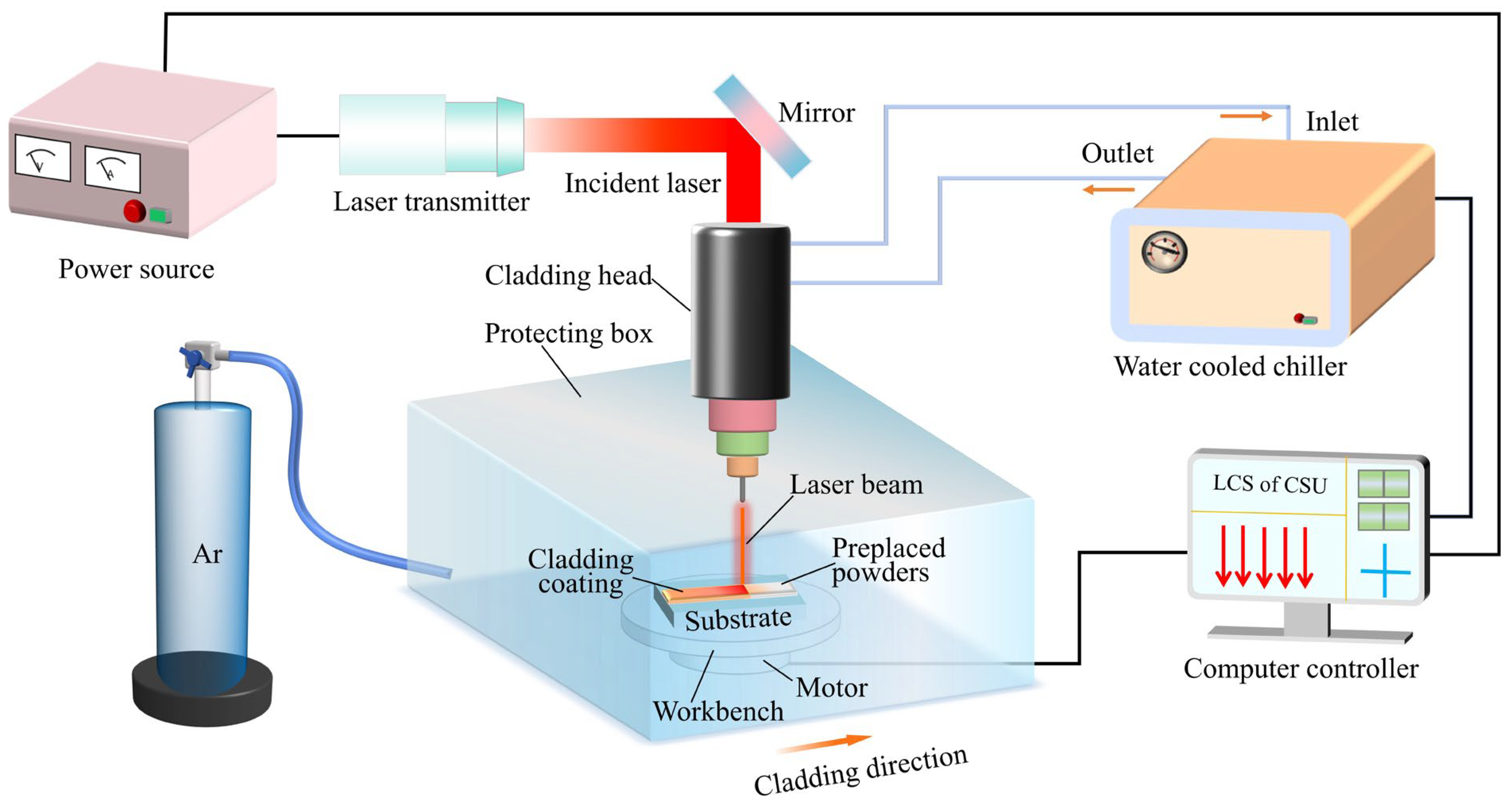
2. Materials and Experiment

2.1. Raw Powders and Preparation of Mixed Powder

TC21 titanium alloy (6.10 wt.% Al, 2.60 wt.% Mo, 1.60 wt.% Cr, 1.70 wt.% Zr, 1.93 wt.% Sn, 1.96 wt.% Nb, 0.13 wt.% Si, 0.09 wt.% O, Ti in balance) was adopted as the substrate metal. Each substrate with dimensions of 30 mm × 15 mm × 8 mm was cleaned with a metal brush to avoid the impact of impurities on the quality of the coatings before laser processing. They were polished to remove the oxide and accelerate the later laser absorption before their surface was rinsed with alcohol in the beaker for ultrasonic cleaning for five minutes and then dried. For ease of identification, Ti powders (≥99.9% purity, ≥300 mesh) and Al powders (≥99.9% purity, 200~300 mesh) were mixed with atomic ratio 1:1, 20 wt.% WC powders (≥99.9% purity, the particle size < 10 μm), and CeO2 powders (≥99.9% purity) of different contents (0.2 wt.%, 0.4 wt.%, 0.6 wt.%, 0.8 wt.%, 1.0 wt.%, 2.0 wt.%) and were respectively added into the resulting mixture as cladding materials to improve the properties of the coating, as listed in Table 1. These blended alloy powders were evenly mixed in an agate mortar by mechanical stirring for 30 min. Before the laser cladding process, the specimens were dried in a vacuum drying oven at a temperature of 50 °C for 24 h, aiming to eliminate moisture present in the cladding powders and effectively prevent oxidation. For the accuracy of the mixed powder composition, the coatings were uniformly fabricated on the test piece using the preplaced powders method. After the mixed powders was compacted on the surface of the TC21 substrate by a special mold, the powders path length was 30 mm, the width was 3 mm, and the thickness was roughly 1 mm.

2.2. Microstructure Characterization

A schematic diagram of the laser cladding process is summarized in Figure 1. Laser cladding coatings were prepared using a LDF 4000-100 fiber laser apparatus (Laserline Company, Koblenz, Germany) (maximum laser power of 6000 W), a defocus amount of 20 mm, and a wavelength of 1070 nm operating in continuous mode. Meanwhile, high-purity argon gas was introduced into the protecting box at a rate of 15 L/min during the cladding process to prevent oxidation of the coating. The laser power was 1000 W, the scanning speed was 3 mm/s, and the spot diameter was 3 mm.
After the laser cladding, the specimens were cut off perpendicular to the cladding direction using a wire electrical discharge machining machine. Thereafter, the specimens underwent standard mechanical polishing followed by etching with a mixture of deionized HF, HNO3, and H2O in a volume ratio of 1:2:30 for approximately 10 s at room temperature. X-ray diffractometer (XRD) (XRD-6000, PANalytical Empyrean, Dordrecht, The Netherlands) with continuous scanning in the range of 20° to 90° was performed to identify the phase constituents of the prepared coatings. The XRD utilized a Cu-Kα irradiation source at a tube voltage and current of 45 kV and 40 mA at room temperature, respectively. Surface morphology and microstructure of the coating were characterized using a scanning electron microscope (SEM) (JSM-7900F, JEOL, Tokyo, Japan) combined with energy dispersive spectrometry (EDS). The electron probe microanalysis (EPMA) (JXA-8530F Plus, JEOL, Japan) approach was employed to reveal the element distribution of the No.6 sample coating.
Microhardness value along the direction of coating depth was measured using a digital micro-Vickers hardness tester (DHV-1000, China) machine with a pressure of 200 gf and a residence time of 15 s. The sample was tested at 100 μm spacing between two points along the depth direction. To reduce the test errors, the hardness value was the average of three test results with the same depth (a 50 μm lateral distance interval). Additionally, the frictional wear tests were conducted at room temperature using a CFT-I surface synthesis tester with a normal applied load of 9.8 N, a sliding speed of 100 mm/s, a sliding distance of 5 mm, a loading time of 30 min, and Si3N4 balls with a diameter of 3 mm as the friction pair. In the interim, a total of 3 repetitions were conducted for each test to guarantee the accuracy of the outcomes, and the average values were considered as the final test results.

3. Results and Discussion

3.1. Phase Constitution
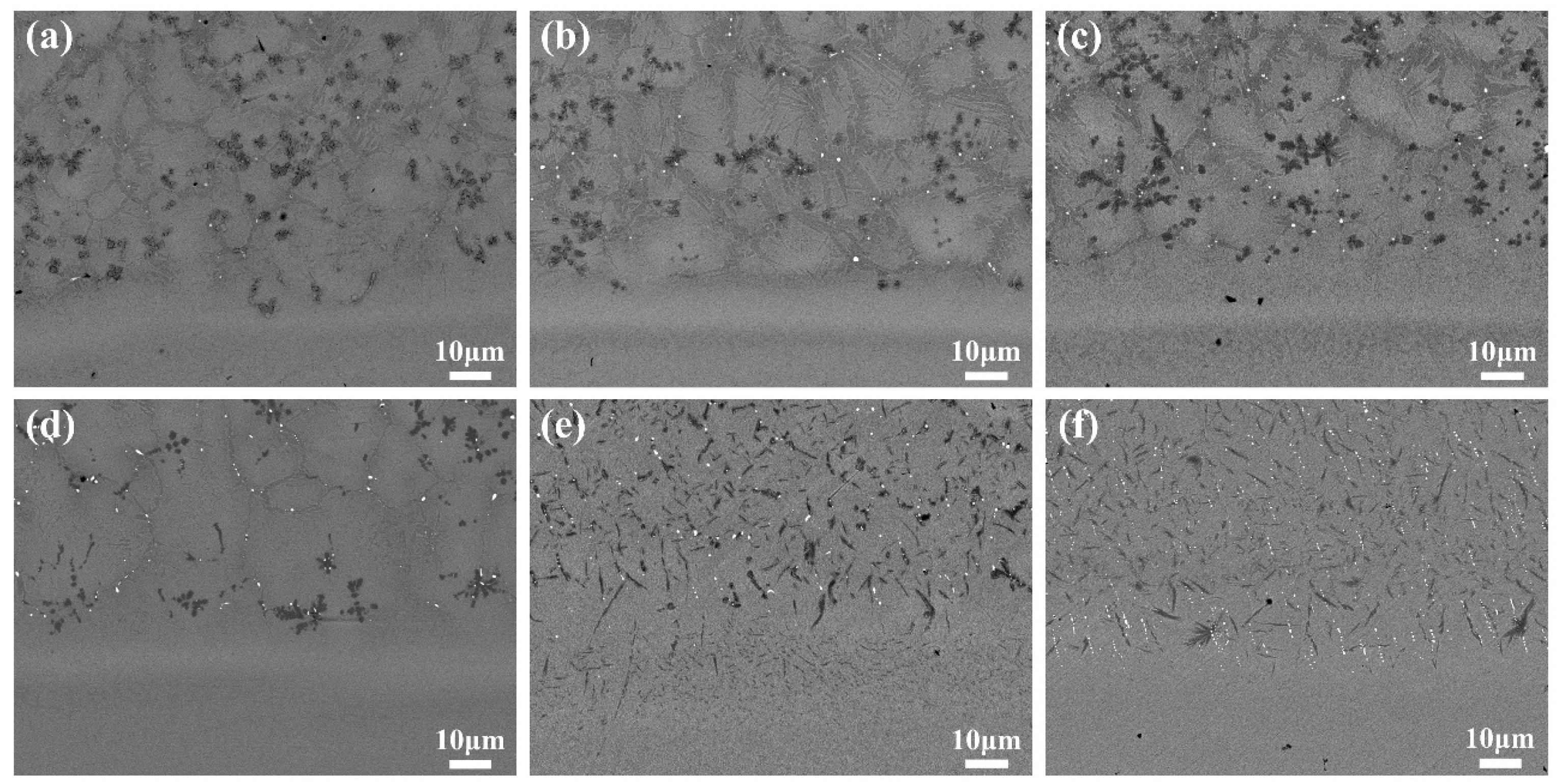
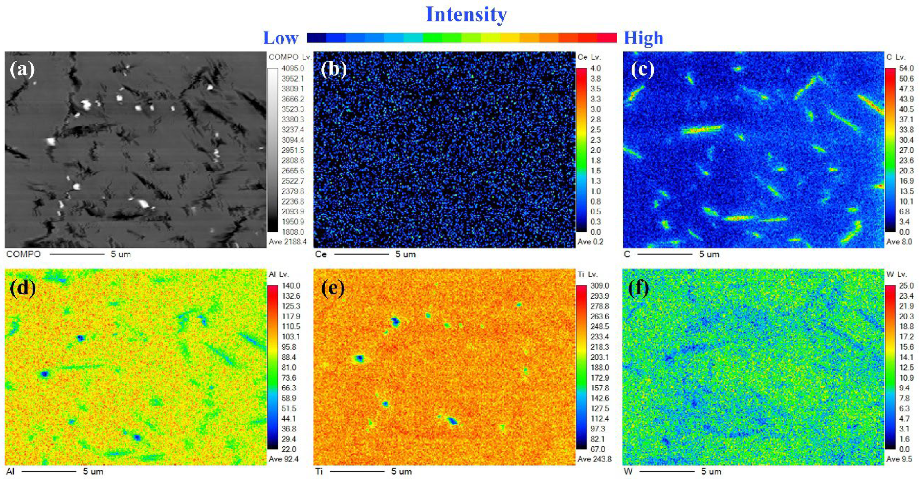
Figure 2 shows the XRD spectrums of the composite coatings with varying CeO2 contents, which presented that the phase compositions of the composite coatings are Ti2AlC, α2-Ti3Al, γ-TiAl, TiC, and CeO2 phases, along with a minor amount of β-Ti and W2C. The absence of WC diffraction peaks in all composite coatings could denote that a significant portion of the WC particles decomposed during the laser cladding process. Owing to the strong chemical affinity between dissociative liquid Ti and the surrounding C, they easily formed the TiC phase in the molten pool through a chemical reaction. The presence of peaks corresponding to TiC in the XRD spectrum of the coatings confirms this transformation.
At the same time, the undissolved WC particles preferred to appear in the middle and bottom of the molten pool under gravity factors [44,45]. As is well-known, the density of WC is much larger than that of TiC and molten Titanium. Simultaneously, the addition of a tiny amount of CeO2 results in a relatively weak diffraction peak strength of CeO2 in cladding coatings. As the amount of CeO2 increases, the relative intensity of the diffraction peaks of TiC, α2-Ti3Al, γ-TiAl, and β-Ti and W2C decrease, while the intensity of the Ti2AlC diffraction peak at 39.2° [46] significantly strengthens, indicating a corresponding increased proportion of the Ti2AlC MAX phase in the coatings. When the additional amount of CeO2 reaches 1.0 wt.%, the intensity of the Ti2AlC diffraction peak is the highest. Moreover, the diffraction peak at 62° for No.1 coating is the W2C phase. For No.2–No.6 coatings, the energy absorption efficiency of laser is improved due to the increase in CeO2 content, and the further decomposition of W2C is promoted. As shown in Figure 2, the coating phase formation indicates that the addition of CeO2 has no significant influence on the phase composition of the cladding coatings.

3.2. Microstructure

Figure 3 reflects the backscattered electron (BSE) images of the TiAl/WC cladding coatings with different CeO2 additions. It can be discovered that the cladding layer is predominantly composed of a greyish-white block phase, a grey phase, white granular phase, and a large number of black phases. The black phases include the dendritic phase (Point 5), petal-like phase, thin strip phase, short rod-like phase, and granular phase. EDS analysis results of these phases are shown in Table 2. It can be determined that the white granular phase (Points 1 and 6) mainly contained Ce and O elements with an atomic ratio close to 1:2, which was expressed as rare earth oxide CeO2. We can clearly observe that the greyish-white block phase (Point 4) mainly contained Ti and Al elements with an atomic ratio close to 3:2, which was expressed as the intermetallic compound (α2 + γ) TiAl. The grey phase (Point 2) mainly contained Ti and Al elements with an atomic ratio close to 1:1, indicating it can be regarded as the intermetallic compound γ-TiAl. EDS results for Points 3 and 5 indicated that the black phase mainly contained Ti and C, which were speculatively considered to be TiC ceramic-reinforced phases combined with their SEM images.
With the continuous increase in CeO2 content, the morphology of TiC has a great influence. It can be clearly seen from Figure 3(a1–d2) that TiC mainly exists in the composite coatings in the form of the black granular phase, dendritic phase, and petal-like phase when CeO2 content is low. Meanwhile, with the continuous increase in CeO2 content, the intergranular structure and the size of the massive structure gradually decrease while refining the structure of the cladding layer. At 1.0 wt.% and 2.0 wt.%, a notable change in the morphology of TiC occurs, with the disappearance of the petal-like phase or coarse dendrite structures and the transformation into numerous finer thin strip phase or short rod-like phase, as depicted in Figure 3(e1–f2). This new form of TiC is uniformly distributed within the crystal structure. Concurrently, the microstructure of the cladding layer becomes obviously refined, with a more uniform distribution of tissues. It is observed that fine CeO2 particles tend to segregate at the grain boundaries, impeding the movement between the phase interface and the grains. Such effective pinning action limits the growth of grains and further refines the grain size.
As shown in Figure 4a–f, it is observed from the interface position between the coatings and the TC21 substrate that there is good metallurgical bonding between the coating and the substrate. Under the action of a laser beam, the substrate is initially slightly melted and then metallurgically bonded with the cladding layer to form a bonding zone of high bonding strength. Massive reinforcing TiC phases in the No.1 to No.4 coatings occupied the bottom of the cladding layer, while the reinforcing phases in the No.5 and No.6 coatings formed the finer thin strip phase, short rod-like phase, and CeO2 white granular to penetrate into the substrate. In Figure 4f, it is evident that at a CeO2 content of 1.0 wt.%, the boundary of the bonding zone in the cladding layer is no longer distinct, with no discernible transition layer. The substrate embedded reinforcing phases, which improved the interface adhesion. However, with the CeO2 content reaching 2.0 wt.% (Figure 4f), although the high content of CeO2 is conducive to tissue refinement, it also increases the dilution rate of the cladding layer and weakens the effect of the reinforcing phase such as TiC. Table 3 illustrates that as the amount of CeO2 increases, the cladding height demonstrates a slight increase, while the cladding width gradually decreases. Moreover, the melting depth and dilution rate of the substrate also gradually increased, especially the melting depth. Previous research [47] has indicated that incorporating an optimal amount of CeO2 into the coating can enhance the energy absorption efficiency of cladding coating for the laser, which promotes more Ti in the substrate to participate in melting and enter the melt pool.
In order to further determine the phase distributions and their relationship with the microstructures, Figure 5 shows the different elements distribution mapping in the No.6 TiAl/WC-CeO2 microregion coating by EPMA. As can be observed from Figure 5c,f, the distribution areas of W and C elements did not coincide. The W elemental maps illustrated that W atoms were dissolved into the (α2 + γ) matrix. On the contrary, the C element was predominantly distributed in numerous TiC-dominated thin strip phases or short rod-like phases, with higher C content in regions with lower W content, which indicated that the WC powders underwent thermal decomposition under the high-energy laser beam action. Figure 5d reveals that the Al atoms mainly existed in the coating matrix and the edge region of TiC reinforcement phases. As can be seen from Figure 5e, the matrix and reinforcement phases were abundant in Ti with a content of more than 95 at.%. Thus, the combination of Figure 5c–e and XRD revealed that the cladding layer contained the TiC/Ti2AlC core-shell reinforcement phase with TiC as the core and Ti2AlC as the shell [48]. The edge region of TiC reinforcement phases was mainly composed of Ti2AlC, and the coating matrix consisted of (α2 + γ) intermetallic compounds. A mixture of α2-Ti3Al and γ-TiAl phase constitutes the (α2 + γ) matrix. On the basis of the above analysis, the introduction of CeO2 promoted the fluidity of the molten pool and further encouraged the diffusion of Ti and Al atoms, resulting in a more uniform distribution of the coating microstructure, which contributed to combine with Al and C elements to form Ti2AlC MAX phase.
To further understand the mechanism of microstructure formation in the coatings, the reaction model between CeO2 and Ti-Al/WC is illustrated in Figure 6. As depicted in Figure 6a,d, pure Ti, Al, WC, and CeO2 are represented as spherical particles, and the WC and CeO2 particles are uniformly mixed by the binder TiAl. The temperature of the molten pool can exceed 2700 K during laser cladding, with transient maximum overheating temperatures reaching up to about 3500 K [49,50]. Not only that, the cooling rate is approximately 6 × 10⁵ K/s, which demonstrates that laser cladding is a typical non-equilibrium solidification process [51]. Therefore, under the Gaussian laser beam irradiation, the precursor powders and partial TC21 substrate are melted immediately. When the temperature exceeds 3000 K, the CeO2 and WC particles are decomposed in the molten pool, creating a high-temperature molten mixture of Ti, Al, W, C, Ce, and O atoms, as shown in Figure 6b,e. Simultaneously, all atoms evenly diffuse and react with each other due to the stirring effect of the laser beam and convection in the molten pool.
In order to comprehend the formation mechanism of the phases, it is essential to initially consider the Gibbs free energy of the phase in the molten pool. The reaction equations involving TiAl/WC/CeO2 composite coatings during the reactions in the molten pool are as follows:
WC → W + C
CeO2 ⇋ Ce + 2O
Ti + C → TiC
Ti + Al → TiAl
3Ti + Al → Ti3Al
TiAl + TiC→Ti2AlC
In fact, as shown in Equation (1), WC will occur in decarburization and dissolution, so that there is a large amount of C element in the molten pool [52]. Compared with that of other compounds, the Gibbs free energy of the TiC compounds is extremely low [53], while the melting point is high. According to the phase diagram of Ti-C, when the C content is about 3 at.% and the temperature drops below 1653 °C, TiC and β-Ti are precipitated in the form of eutectic. When the content of C is high, TiC will consume C of the molten pool from primary TiC to eventually dendritic. Therefore, with the departure of the laser energy, the surrounding C element will be consumed, and TiC phases as coarse dendrites precipitated preferentially from the molten liquid owing to the high affinity between Ti and C atoms. The TiC reinforcing phase is first generated in the reaction. Figure 7 shows the Ti-Al binary phase diagram. In this diagram, Ti reacts with Al to form four intermetallic compounds: Ti3Al, TiAl, TiAl2, and TiAl3. According to the XRD analysis results, only the Ti3Al and TiAl were detected in the coatings. It is mainly attributed that the atom ratio of Ti and Al is 1:1, so the main product should be γ-TiAl [54]. Meanwhile, due to the TC21 substrate melting in the laser cladding process, a large number of Ti elements rush into the molten pool, resulting in the solidification path moving to the left. It can be seen from Figure 7 that when the content of Ti is high, the generated product is mainly Ti3Al [55]. In addition, due to the high chemical activity of Ce element, it is difficult for CeO to exist in the molten pool as single substance, so it will recombine with O to form CeO2 distributed between the grain boundaries.
With the continuous cooling of the molten pool, a portion of the in situ precipitated TiC will react with uncoagulated Ti-A1 melts to form the ternary compound Ti2AlC MAX phase around the edge region of TiC in combination with the aforementioned XRD and EPMA analysis results. As shown in Figure 6c,f, the microstructure of the obtained coating became significantly denser and more uniform as the CeO2 content increased to 1.0 wt.%. The distribution of the Ti2AlC MAX phase tended to increase, while the TiC thin strip tissue gradually intensified, and the massive shape γ-TiAl became finer. The Ti2AlC MAX phase and TiC reinforced phase were evenly distributed on the refined (α2 + γ) matrix. This is attributed to the doped-CeO2 in the liquid pool which could absorb more laser beam energy, forming a more uniform microstructure and facilitating the emergence and transformation of the MAX phase. During the laser cladding process, the increase in heat input energy leads to a greater undercooling of the coating. On the one hand, due to the high nucleation rate, the growth of the grain is blocked; therefore, the thin strip short rod-like TiC reinforcement phases could be acquired because of the large component undercooling and the extremely fast solidification rate. On the other hand, the CeO2 in the liquid pool acts like a diluter. A large amount of Ti elements from the substrate entered the reaction of the cladding layer, which caused a deficiency in the C atoms needed for the TiC phase formation in the coating, thereby reducing the growth driving force of TiC. Eventually, the dendritic structures are not preserved in the coating and the majority of the coating matrix is covered by the refined reinforcing phases.

3.3. Microhardness

Figure 8a illustrates the distribution of microhardness along the depth direction from the coating surface to the substrate, showcasing the microhardness values of coatings with distinct CeO2 content. Overall, from the composite coatings to the substrate, the microhardness distribution curves demonstrate a progressive declining tendency. The fluctuation of the microhardness value is relatively stable in the cladding zone, whereas it decreases rapidly in the bonding zone. Additionally, the microhardness decreases slowly from the heat-affected zone to the substrate. As depicted in Figure 8b, the average microhardness of the No.1~No.6 coatings were approximately 626.7 HV0.2, 607.1 HV0.2, 630.8 HV0.2, 599.2 HV0.2, 596.4 HV0.2, and 584.1 HV0.2, respectively. A notable feature observation is that the average microhardness of the TiAl/WC coatings with different CeO2 content is considerably higher than that of the TC21 alloy, due to the addition of WC powder, which can be decomposed into free C atoms and W atoms under the high energy of laser cladding [56]. The generated intermetallic compounds and carbides act as a reinforcing machine, which is made of dispersion strengthening and refinement strengthening (such as TiC, Ti2AlC, Ti-Al, and CeO2). However, it is evident that as the CeO2 content increased, the overall microhardness of the cladding zone showed a decreasing trend, albeit not significantly, i.e., by only less than 8%. On the one hand, the main reason for this phenomenon is that the TiC morphology gradually changes from dendritic or petal shaped to thin strip phase and short rod-like phase, resulting in a decrease in the overall content of the TiC reinforcing phase. On the other hand, the Ti2AlC MAX phase structure with a lower hardness (in comparison to the TiC reinforcing phase) became predominant, owing to a progressive rise in the MAX phase content, which in turn impacts the enhancement effect of coating average microhardness. Moreover, the addition of CeO2 effectively improved the uniformity of the distribution of elements and the relative compactness of the microstructure and decreased the fluctuation range of hardness to a certain extent.

3.4. Wear Behavior Analysis

Figure 9a depicts the tribological properties of coatings and substrate on the Si3N4 sphere in a dry sliding wear test conducted at room temperature. It can be seen that the friction coefficient of the No.1 coating presents noticeable fluctuations. At the onset of the wear period, the friction coefficient of the No.1 coating is low, but it gradually increases over time and eventually stabilizes between 0.45 and 0.55. This can be explained by the fact that during the initial wear stage, point contact occurs between the smooth sample surface and the Si3N4 ball [45]. As the friction wear test progressed, the friction surface produced abrasive particles. The accumulation of these abrasive particles leads to an increase in the surface contact area and friction resistance, which is expressed as the increase in friction coefficient. The friction coefficient of the No.2 coating is generally stable, but its value is the highest. As the amount of CeO2 increases, the friction coefficient of the No.3 coating and No.4 coating gradually decreases, reaching the lowest value at the No.4 coating. In combination with Figure 3(a1–d2), it can be seen that the distribution of the TiC reinforcing phase on the surface of the No.1 coating is relatively uneven, resulting in a certain fluctuation of friction coefficient. The microstructure of the No.4 coating is relatively denser and uniform, with the TiC phase predominantly present in petal-like and dendritic structures. Throughout the wear test, the dispersed and reinforced TiC phases in situ formed within the coating played a “skeleton” role, which bears the main load and effectively prevents further wear [41]. This strengthens the anti-wear performance of the coatings and results in a low friction coefficient. However, as the amount of CeO2 continued to increase, the friction coefficient of the No.5~6 coating increased more than that of the No.4 coating, and its fluctuation is not obvious. The TiC morphology underwent significant changes in the cladding layer structure, appearing as thin strips or short rod-like phases, which reduced the support provided by the cladding layer during friction pair interaction simultaneously, due to the predominant Ti2AlC MAX phase structure with lower hardness. Low hardness is not conducive to an improvement in wear resistance. Furthermore, combined with Figure 5e,f, it can be seen that the rise in the friction coefficient is primarily attributed to the fact that under the stirring action of CeO2, the TiC reinforced phase is more evenly distributed throughout the cladding layer without an obvious binding zone. The reinforced phase is embedded in the substrate, and therefore, the interface adhesion is improved. Nevertheless, when the coating surface is rubbed, it also weakens the enhancement effect of the TiC phase, which may be related to the high friction coefficients of No.5 and No.6.
Figure 9b shows the wear weight loss of the TiAl/WC coatings with different CeO2 content. The average wear weight loss of the No.1~No.6 coatings was approximately 1.4 mg, 2.3 mg, 2.1 mg, 1.2 mg, 3.5 mg, and 4.7 mg, respectively. The decrease in wear weight loss signifies the enhancement in wear resistance. Aforementioned results demonstrated that the wear weight loss is the lowest among the series of specimens when the additive amount of CeO2 was 0.8 wt.%. On the whole, with the increase in CeO2 content, the wear weight loss of each coating is consistent with the change law of the friction coefficient.

4. Conclusions

In this paper, the TiAl/WC/CeO2 cermet composite coatings were prepared on TC21 titanium alloy substrate using laser cladding technology. The influences of CeO2 content on composite coatings on the phase distribution, microstructure evolution, formation mechanisms, and microhardness were comprehensively investigated. Accordingly, the primary conclusions are as follows:
(1)
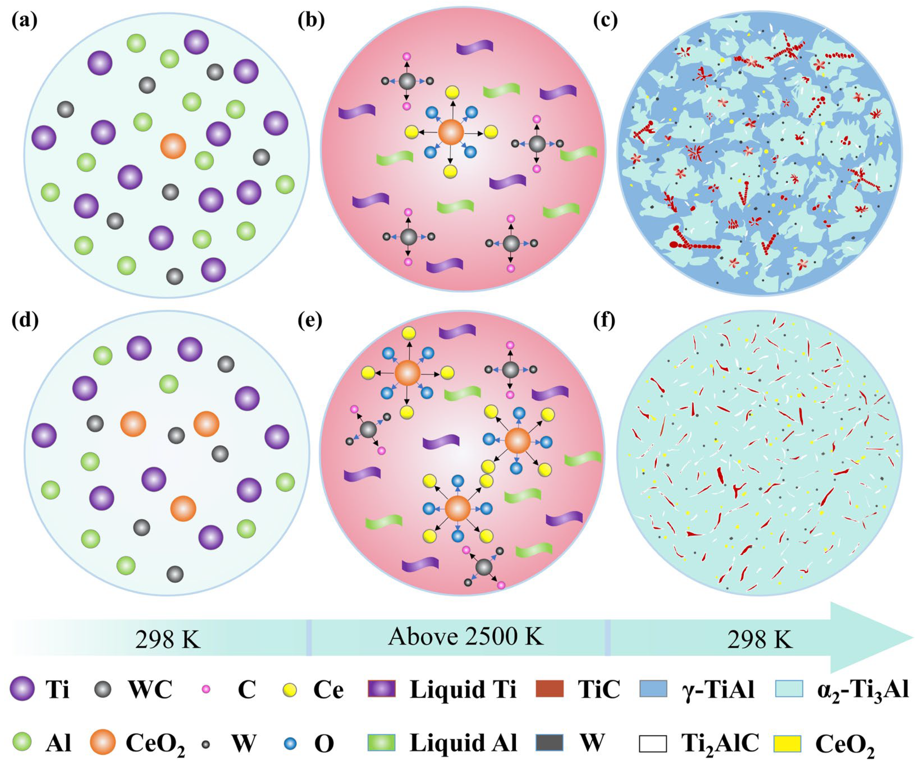
The addition of CeO2 content has no influential change on the phase composition structure of composite coatings, which were composed of Ti2AlC, α2-Ti3Al, γ-TiAl, TiC, and CeO2 phases, along with a minor amount of β-Ti.
(2)
The TiC/Ti2AlC core-shell reinforcement phase can be in situ synthesized in the coating, and the addition of CeO2 content significantly influences the morphology, size, and distribution of the TiC reinforcing phase in the composite coatings. Furthermore, with the addition of CeO2, the fluidity of the molten pool is enhanced, and the microstructure refinement of composite coatings is improved.
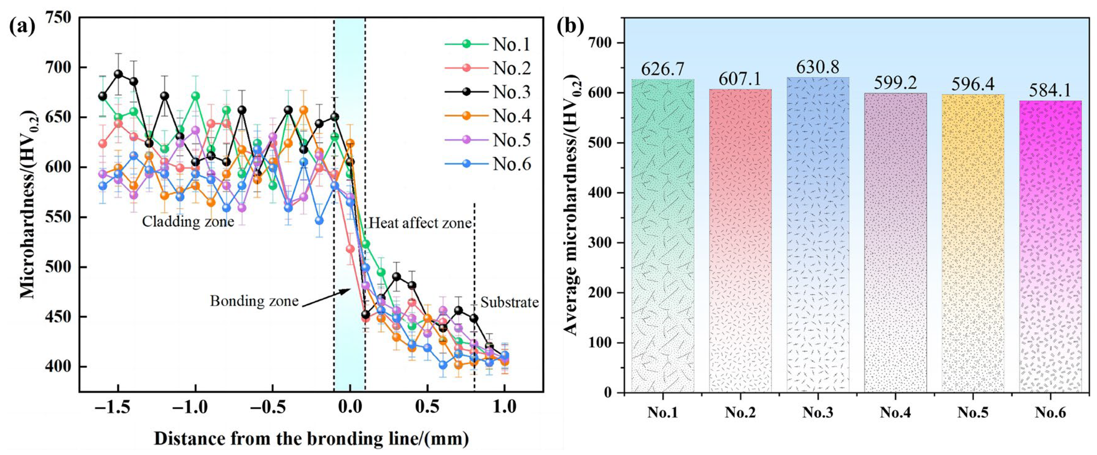
(3)
While the content of CeO2 is 0.6 wt.%, the microhardness reaches a maximum value of about 700 HV0.2. Compared with substrate, the average microhardness 630.8 HV0.2 has increased almost 1.6 times. When the addition of CeO2 is 0.8 wt.%, the comprehensive mechanical property is the best. The wear resistance of the TiAl/WC/CeO2 composite coatings is dramatically enhanced due to the reinforcing phases of homogeneous distribution and the fine grain strengthening and dispersion strengthening effects of CeO2, contributing directly to generate a lower friction coefficient with a small range of fluctuation.

Author Contributions

Conceptualization, X.S. and J.L.; Software, L.Z.; Validation, J.L.; Investigation, L.Z.; Resources, W.Z.; Data curation, L.Z.; Writing—original draft, X.S.; Writing—review & editing, Y.W.; Visualization, Y.W., X.H. and F.L.; Supervision, W.Z.; Project administration, W.Z.; Funding acquisition, X.S., Y.W. and J.L. All authors have read and agreed to the published version of the manuscript.

Funding

This work was supported by the Guangxi Science and Technology Program (Guike AD23026170, Guike AD23026116), the Guangxi Key Laboratory of Manufacturing System and Advanced Manufacturing Technology (Grant No. 22-35-4-S019), the Research Basic Ability Enhancement Program for Young and Middle-aged Teachers of Guangxi (2023KY0202), the Guilin Science and Technology Development Program (Project) (20220124-10), and the Innovation Project of GUET Graduate Education (2024YCXS008).

Institutional Review Board Statement

Not applicable.

Informed Consent Statement

Not applicable.

Data Availability Statement

The data presented in this study are available on request from the corresponding author.

Conflicts of Interest

Jian Lu was employed by the company China Nonferrous Metals (Guilin) Geology and Mining Co., Ltd. The remaining authors declare that the research was conducted in the absence of any commercial or financial relationships that could be construed as a potential conflict of interest.

References

  1. Zhang, D.; Qiu, D.; Gibson, M.A.; Zheng, Y.; Fraser, H.L.; StJohn, D.H.; Easton, M.A. Additive manufacturing of ultrafine-grained high-strength titanium alloys. Nature 2019, 576, 91–95. [Google Scholar] [CrossRef] [PubMed]
  2. Yao, Z.; He, M.; Yi, J.; Yang, M.; Shi, R.; Wang, C.; Zhong, Z.; Yang, T.; Wang, S.; Liu, X. High-strength titanium alloy with hierarchical-microstructure design via in-situ refinement-splitting strategy in additive manufacturing. Addit. Manuf. 2024, 80, 103969. [Google Scholar] [CrossRef]
  3. Li, G.; Chandra, S.; Rashid, R.A.R.; Palanisamy, S.; Ding, S. Machinability of additively manufactured titanium alloys: A comprehensive review. J. Manuf. Process. 2022, 75, 72–99. [Google Scholar] [CrossRef]
  4. Alipour, S.; Moridi, A.; Liou, F.; Emdadi, A. The Trajectory of Additively Manufactured Titanium Alloys with Superior Mechanical Properties and Engineered Microstructures. Addit. Manuf. 2022, 60, 103245. [Google Scholar] [CrossRef]
  5. Hua, K.; Ding, H.; Sun, L.; Cao, Y.; Li, X.; Wu, H.; Wang, H. Enhancing high-temperature fretting wear resistance of TC21 titanium alloys by laser cladding self-lubricating composite coatings. J. Alloys Compd. 2024, 977, 173360. [Google Scholar] [CrossRef]
  6. Guo, X.; Ma, M.; Zhang, S.; Wei, Z. Microstructure and wear resistance of tungsten carbide particle reinforced titanium alloy coating by WAAM. Tribol. Int. 2024, 194, 109536. [Google Scholar] [CrossRef]
  7. Bai, H.; Zhong, L.; Kang, L.; Liu, J.; Zhuang, W.; Lv, Z.; Xu, Y. A review on wear-resistant coating with high hardness and high toughness on the surface of titanium alloy. J. Alloys Compd. 2021, 882, 160645. [Google Scholar] [CrossRef]
  8. Gao, K.; Zhang, Y.; Yi, J.; Dong, F.; Chen, P. Overview of Surface Modification Techniques for Titanium Alloys in Modern Material Science: A Comprehensive Analysis. Coatings 2024, 14, 148. [Google Scholar] [CrossRef]
  9. Tian, N.; Guan, J.; Zhang, C.; Lyu, P.; Peng, C.; Cai, J.; Guan, Q. Influence of high-current pulsed electron beam irradiation on element diffusion behavior and mechanical properties of TC4/304 stainless steel diffusion bonded joints. Mater. Charact. 2023, 198, 112713. [Google Scholar] [CrossRef]
  10. Garcia, M.A.; Gago, R.; Arroyo-Hernández, M.; De Laorden, E.H.; Iglesias, M.; Esteban-Mendoza, D.; Cuerno, R.; Rickards, J. Texturization of polycrystalline titanium surfaces after low-energy ion-beam irradiation: Impact on biocompatibility. Surf. Coat. Technol. 2023, 458, 129363. [Google Scholar] [CrossRef]
  11. Sinyakova, E.A.; Panin, A.V.; Perevalova, O.B.; Shugurov, A.R.; Kalashnikov, M.P.; Teresov, D. The effect of phase transformations on the recovery of pulsed electron beam irradiated Ti-6Al-4V titanium alloy during scratching. J. Alloys Compd. 2019, 795, 275–283. [Google Scholar] [CrossRef]
  12. Qiu, L.; Chen, H.; Zeng, F.; Zhou, S.; Ye, Y.; Cheng, W.; Zhong, Z.; Du, Y. Microstructure, mechanical properties and cutting performance of super-hard Ti(B,C,N) coatings prepared by chemical vapor deposition method. Surf. Coat. Technol. 2024, 480, 130599. [Google Scholar] [CrossRef]
  13. Koshuro, V.; Fomina, M.; Zakharevich, A.; Fomin, A. Superhard Ta–O–N coatings produced on titanium using induction physical vapor deposition. Ceram. Int. 2022, 48, 19467–19483. [Google Scholar] [CrossRef]
  14. Yu, H.; Liang, W.; Miao, Q.; Yin, M.; Chen, H.; Yao, W.; Sun, Y.; Zang, K.; Gao, X.; Song, Y. Microstructure and wear behavior of (ZrTaNb)C/N quaternary ceramic coatings prepared by double-cathode glow plasma surface alloying on titanium alloy. Wear 2023, 523, 204789. [Google Scholar] [CrossRef]
  15. Wang, X.; Yang, Y.; Zhao, Y.; Zhang, X.; Wang, Y.; Tian, W. Effects of B4C particle size and content on microstructure and properties of in-situ TiB2-TiC composite coatings prepared by plasma spraying. Surf. Coat. Technol. 2023, 459, 129273. [Google Scholar] [CrossRef]
  16. Wang, Y.; Wei, D.; Wang, L.; Zhang, L.; Liu, J.; Tang, Y.; Fu, Y.; Lu, W. Surface modification and twinning behavior in gradient graphene-based TiC/Ti6Al4V composite. Appl. Surf. Sci. 2022, 583, 152495. [Google Scholar] [CrossRef]
  17. Zhang, H.; Cui, H.; Man, C.; Liu, F.; Pang, K.; Ma, G.; Chen, H.; Cui, Z. The tribocorrosion resistance of TiN+TiB/TC4 composite coatings and the synergistic strengthening effects of multi-level reinforcements. Corros. Sci. 2023, 219, 111224. [Google Scholar] [CrossRef]
  18. Liu, Y.; Yang, Y.; Chen, C. Microstructure and properties of Ni-Ti based gradient laser cladding layer of Ti6Al4V alloy by laser powder bed fusion. Addit. Manuf. 2024, 79, 103906. [Google Scholar] [CrossRef]
  19. Zhang, H.; Pan, Y.; Zhang, Y.; Lian, G.; Cao, Q.; Que, L. Microstructure, toughness, and tribological properties of laser cladded Mo2FeB2-based composite coating with in situ synthesized WC and La2O3 addition. Surf. Coat. Technol. 2022, 449, 128947. [Google Scholar] [CrossRef]
  20. Tan, C.Y.; Wen, C.; Ang, H.Q. Influence of laser parameters on the microstructures and surface properties in laser surface modification of biomedical magnesium alloys. J. Magnes. Alloys 2024, 12, 72–97. [Google Scholar] [CrossRef]
  21. Shen, Z.; Su, H.; Yu, M.; Guo, Y.; Liu, Y.; Zhao, D.; Jiang, H.; Yang, P.; Yang, M.; Zhang, Z.; et al. Large-size complex-structure ternary eutectic ceramic fabricated using laser powder bed fusion assisted with finite element analysis. Addit. Manuf. 2023, 72, 103627. [Google Scholar]
  22. He, S.; Yao, C.; Shin, K.-Y.; Park, S.; Shim, D. Microstructure and wear behaviors of a WC10%-Ni60AA cermet coating synthesized by laser-directed energy deposition. Surf. Coat. Technol. 2024, 478, 130393. [Google Scholar] [CrossRef]
  23. Genc, O.; Unal, R. Development of gamma titanium aluminide (γ-TiAl) alloys: A review. J. Alloys Compd. 2022, 929, 167262. [Google Scholar] [CrossRef]
  24. Fan, T. The influence of induction-assisted milling on the machining characteristics and surface integrity of γ-TiAl alloys. J. Manuf. Process. 2024, 118, 215–227. [Google Scholar] [CrossRef]
  25. Pan, Y.; Han, D.; Huang, S.; Niu, Y.; Liang, B.; Zheng, X. Thermal insulation performance and thermal shock resistance of plasma-sprayed TiAlCrY/Gd2Zr2O7 thermal barrier coating on γ-TiAl alloy. Surf. Coat. Technol. 2023, 468, 129715. [Google Scholar] [CrossRef]
  26. Qi, C.; Zhan, X.; Gao, Q.; Liu, L.; Song, Y.; Li, Y. The influence of the pre-placed powder layers on the morphology, microscopic characteristics and microhardness of Ti-6Al-4V/WC MMC coatings during laser cladding. Opt. Laser Technol. 2019, 119, 105572. [Google Scholar] [CrossRef]
  27. Li, Z.; Xie, D.; Liu, Y.; Lv, F.; Zhou, K.; Jiao, C.; Gao, X.; Wang, D.; Liu, Y.; Zu, H.; et al. Effect of WC on the microstructure and mechanical properties of laser-clad AlCoCrFeNi2.1 eutectic high-entropy alloy composite coatings. J. Alloys Compd. 2024, 976, 173219. [Google Scholar] [CrossRef]
  28. You, A.; Wang, N.; Chen, Y.; Jiang, C.; Zhang, Y.; Zhao, Q.; Shi, Y.; Li, Y.; Zhang, F.; Zhao, Y. Effect of linear energy density on microstructure and wear resistance of WC-Co-Cr composite coating by laser cladding. Surf. Coat. Technol. 2023, 454, 129185. [Google Scholar] [CrossRef]
  29. Yang, X.; Wang, L.; Gao, Z.; Wang, Q.; Du, M.; Zhan, X. WC distribution, microstructure evolution mechanism and microhardness of a developed Ti-6Al-4 V/WC MMC coating fabricated by laser cladding. Opt. Laser Technol. 2022, 153, 108232. [Google Scholar] [CrossRef]
  30. Yang, C.; Jing, C.; Fu, T.; Lin, T.; Guo, W.; Liu, N. Effect of CeO2 on the microstructure and properties of AlCoCrFeNi2.1 laser cladding coatings. J. Alloys Compd. 2024, 976, 172948. [Google Scholar] [CrossRef]
  31. Murmu, A.M.; Parida, S.K.; Das, A.K.; Kumar, S. Evaluation of laser cladding of Ti6Al4V-ZrO2-CeO2 composite coating on Ti6Al4V alloy substrate. Surf. Coat. Technol. 2023, 473, 129988. [Google Scholar] [CrossRef]
  32. Su, Z.; Li, J.; Shi, Y.; Zhang, Z.; Wang, X.; Hou, G. Effect of Y2O3 addition on the organization and tribological properties of Ni60A/Cr3C2 composite coatings obtained by laser-cladding. Ceram. Int. 2024, 50, 17261–17273. [Google Scholar] [CrossRef]
  33. Xing, S.; Zhu, W.; You, S.; Yu, W.; Jiang, C.; Ji, V. Investigation on microstructure and tribological performances of electrodeposited Ni-W-Y2O3 composite coatings. J. Alloys Compd. 2023, 965, 171397. [Google Scholar] [CrossRef]
  34. Zhang, K.; Wang, W.; Liu, W.; Liu, C.; Geng, J.; Wang, H.; Bian, H. Effect of Sm2O3 particles on microstructure and properties of FeCoNiCrMn composite coating by laser cladding. Mater. Chem. Phys. 2024, 317, 129168. [Google Scholar] [CrossRef]
  35. Cheng, X.; He, Y.; Song, R.; Li, H.; Liu, B.; Zhou, H.; Yan, L. Study of mechanical character and corrosion properties of La2O3 nanoparticle reinforced Ni-W composite coatings. Colloids Surf. A 2022, 652, 129799. [Google Scholar] [CrossRef]
  36. Fan, Y.; Chen, F.; Cao, S.; Hu, Y.; Xie, R.; Yang, Y. Effect of interlayer coating La2O3 particles on arc behavior and microstructure of wire arc additive manufacturing Al-Si alloy deposition. J. Manuf. Process. 2023, 101, 943–958. [Google Scholar] [CrossRef]
  37. Zhang, Z.; Yang, F.; Zhang, H.; Zhang, T.; Wang, H.; Xu, Y.; Ma, Q. Influence of CeO2 addition on forming quality and microstructure of TiC -reinforced CrTi4-based laser cladding composite coating. Mater. Charact. 2021, 171, 110732. [Google Scholar] [CrossRef]
  38. He, R. A novel approach to regulate the microstructure of laser-clad FeCrNiMnAl high entropy alloy via CeO2 nanoparticles. Coat. Technol. 2023, 473, 130026. [Google Scholar] [CrossRef]
  39. Zheng, C.; Huang, K.; Mi, T.; Li, M.; Li, S.; Yi, X. Impact of CeO2 modification on the quality and wear performance of Al2O3/SiC reinforced metal-based coatings. Mater. Charact. 2024, 208, 113641. [Google Scholar] [CrossRef]
  40. Li, S.; Huang, K.; Zhang, Z.; Zheng, C.; Li, M.; Wang, L.; Wu, K.; Tan, H.; Yi, X. Wear mechanisms and micro-evaluation of WC + TiC particle-reinforced Ni-based composite coatings fabricated by laser cladding. Mater. Charact. 2023, 197, 112699. [Google Scholar] [CrossRef]
  41. Liu, Y.; Yang, L.; Yang, X.; Zhang, T.; Sun, R. Optimization of microstructure and properties of composite coatings by laser cladding on titanium alloy. Ceram. Int. 2021, 47, 2230–2243. [Google Scholar] [CrossRef]
  42. Shu, D.; Dai, S.; Wang, G.; Si, W.; Xiao, P.; Cui, X.; Chen, X. Influence of CeO2 content on WC morphology and mechanical properties of WC/Ni matrix composites coating prepared by laser in-situ synthesis method. J. Mater. Res. Technol. 2020, 9, 11111–11120. [Google Scholar] [CrossRef]
  43. Yang, R.; Tian, Y.; Huang, N.; Lu, P.; Chen, H.; Li, H.; Chen, X. Effects of CeO2 addition on microstructure and cavitation erosion resistance of laser-processed Ni-WC composites. Mater. Lett. 2022, 311, 131583. [Google Scholar] [CrossRef]
  44. Chen, H.; Lu, Y.; Wu, K.; Wang, X.; Liu, D. Effect of WC addition on TiC reinforced Fe matrix composites produced by laser deposition. Surf. Coat. Technol. 2022, 434, 128185. [Google Scholar] [CrossRef]
  45. Hu, Z.; Li, Y.; Lu, B.; Tan, N.; Cai, L.; Yong, Q. Effect of WC content on microstructure and properties of high-speed laser cladding Ni-based coating. Opt. Laser Technol. 2022, 155, 108449. [Google Scholar] [CrossRef]
  46. Chen, J.; Zhang, F.; Yan, S.; Yu, G.; He, J.; Yin, F. Effect of Ti content and annealing on microstructure and mechanical performance of plasma sprayed Ti–Al–C based composite coatings. Vacuum 2023, 209, 111817. [Google Scholar] [CrossRef]
  47. Jianing, L.; Chuanzhong, C.; Cuifang, Z. Effect of nano-CeO2 on microstructure properties of TiC/TiN+nTi(CN) reinforced composite coating. Bull. Mater. Sci. 2012, 35, 399–404. [Google Scholar] [CrossRef]
  48. Tian, Y.; Xiao, H.; Ren, L.; Feng, J.; Xiao, Y.; Chen, N.; Zhou, X. A new strategy to fabricate Ti2AlC MAX coatings by the two-step laser method. Surf. Coat. Technol. 2022, 448, 128944. [Google Scholar] [CrossRef]
  49. Tran, H.-S.; Tchuindjang, J.T.; Paydas, H.; Mertens, A.; Jardin, R.T.; Duchêne, L.; Carrus, R.; Lecomte-Beckers, J.; Habraken, A.M. 3D thermal finite element analysis of laser cladding processed Ti-6Al-4V part with microstructural correlations. Mater. Des. 2017, 128, 130–142. [Google Scholar] [CrossRef]
  50. Liu, Y.; Wu, Z.; Liu, W.; Ma, Y.; Zhang, X.; Zhao, L.; Yang, K.; Chen, Y.; Cai, Q.; Song, Y.; et al. Microstructure evolution and reaction mechanism of continuously compositionally Ti/Al intermetallic graded material fabricated by laser powder deposition. J. Mater. Res. Technol. 2022, 20, 4173–4185. [Google Scholar] [CrossRef]
  51. Jiang, C.; Zhang, J.; Chen, Y.; Hou, Z.; Zhao, Q.; Li, Y.; Zhu, L.; Zhang, F.; Zhao, Y. On enhancing wear resistance of titanium alloys by laser cladded WC-Co composite coatings. Int. J. Refract. Met. Hard Mater. 2022, 107, 105902. [Google Scholar] [CrossRef]
  52. Wei, T.; Xiaoyu, H.; Peng, L.; Dejun, K. Effect of in-situ grown TiC on microstructure and tribological performance of laser cladded NiCrAl-40%WC coating by addition of Ti. Opt. Laser Technol. 2022, 156, 108541. [Google Scholar] [CrossRef]
  53. Li, J.; Shao, H.; Liu, T.; Zhang, K.; Yan, Z.; Liao, W. Preparation of Ti2AlC through in-situ selective laser forming and reaction sintering. Ceram. Int. 2021, 47, 22356–22364. [Google Scholar] [CrossRef]
  54. Školáková, A.; Leitner, J.; Salvetr, P.; Novák, P.; Deduytsche, D.; Kopeček, J.; Detavernier, C.; Vojtěch, D. Kinetic and thermodynamic description of intermediary phases formation in Ti–Al system during reactive sintering. Mater. Chem. Phys. 2019, 230, 122–130. [Google Scholar] [CrossRef]
  55. Sui, X.; Lu, J.; Hu, J.; Zhang, W. Effect of specific energy on microstructure and properties of laser cladded TiN/Ti3AlN-Ti3Al composite coating. Opt. Laser Technol. 2020, 131, 106428. [Google Scholar] [CrossRef]
  56. Zhang, M.; Li, M.; Chi, J.; Wang, S.; Yang, S.; Yang, J.; Wei, Y. Effect of Ti on microstructure characteristics, carbide precipitation mechanism and tribological behavior of different WC types reinforced Ni-based gradient coating. Surf. Coat. Technol. 2019, 374, 645–655. [Google Scholar] [CrossRef]
Figure 1. Schematic diagram of the laser cladding process.
Coatings 14 00543 g001
Figure 2. XRD patterns of the composite coatings.
Coatings 14 00543 g002
Figure 3. SEM images of the composite coating under different CeO2 content: (a1,a2) 0.2 wt.%, (b1,b2) 0.4 wt.%, (c1,c2) 0.6 wt.%, (d1,d2) 0.8 wt.%, (e1,e2) 1.0 wt.%, and (f1,f2) 2.0 wt.% CeO2.
Coatings 14 00543 g003
Figure 4. SEM images of microstructure of the bonding zone under different CeO2 content: (a) 0.2 wt.%, (b) 0.4 wt.%, (c) 0.6 wt.%, (d) 0.8 wt.%, (e) 1.0 wt.%, and (f) 2.0 wt.%.
Coatings 14 00543 g004
Figure 5. SEM images and corresponding EPMA element maps of the No.6 microstructure. (a) Composite coating with 2.0 wt.% CeO2, (b) Ce, (c) C, (d) Al, (e) Ti, and (f) W.
Coatings 14 00543 g005
Figure 6. The simplified diagram of microstructure formation mechanism for the coating. (ac) the TiAl/WC composite coatings with low content of CeO2, (df) the TiAl/WC composite coatings with high content of CeO2.
Coatings 14 00543 g006
Figure 7. Ti-Al binary phase diagram [55].
Coatings 14 00543 g007
Figure 8. Microhardness properties of the coatings in terms of various CeO2 content: (a) the hardness distribution across the cross-section, (b) the average hardness histogram.
Coatings 14 00543 g008
Figure 9. The variation of friction wear of TiAl/WC/CeO2 composite coating in dry friction and wear test at room temperature. (a) The friction coefficient curves of coatings with time, (b) the total wear weight loss of coatings.
Coatings 14 00543 g009
Table 1. Chemical composition of the powder precursor (wt.%).
SpecimenTi-AlWCCeO2
No.179.8200.2
No.279.6200.4
No.379.4200.6
No.479.2200.8
No.579.0201.0
No.678.0202.0
Table 2. The corresponding EDS results marked in Figure 3 (atomic fraction %).
ZonesTiAlCWCeOPossible
Phase
Point 116.4616.4839.110.505.4122.04CeO2
Point 228.8919.7150.391.01--γ-TiAl
Point 326.0810.4451.520.640.0711.25TiC
Point 430.4320.2347.981.36--2 + γ)
Point 537.549.7951.950.72--TiC
Point 611.6613.3942.690.748.0223.51CeO2
Table 3. Technological parameters of composite coatings.
SpecimenCoating Width
W1/μm
Coating Height
H/μm
TC21 Substrate Melting Depth
D/μm
Dilution Rate
η/%
No.14743.81661.16183.8821.76
No.24440.07606.74239.7028.32
No.34296.48801.51326.6328.95
No.44268.29902.44480.4934.74
No.53784.31791.67779.4149.61
No.63699.47944.151164.8955.23
Disclaimer/Publisher’s Note: The statements, opinions and data contained in all publications are solely those of the individual author(s) and contributor(s) and not of MDPI and/or the editor(s). MDPI and/or the editor(s) disclaim responsibility for any injury to people or property resulting from any ideas, methods, instructions or products referred to in the content.

