1. Introduction
Carbon fiber is a fiber material composed of carbon atoms. It possesses not only low density and high strength but also excellent high-temperature and low-temperature resistance, good thermal shock resistance, a low thermal expansion coefficient, and outstanding corrosion resistance. Carbon fiber reinforced polymers (CFRP) find extensive applications in critical industries such as aerospace, automotive, rail transportation, wind energy, and construction [
1].
The use of CFRP is the primary approach for aircraft lightweighting in the current aviation industry. The range and application areas of CFRP have become crucial indicators for assessing the level of aircraft structural advancement. Additionally, they serve as important criteria for airlines when purchasing aircraft. With the continuous increase in the proportion of CFRP in aircraft components, the issue of connecting CFRP with traditional lightweight alloys such as aluminum alloys has become inevitable. The traditional mechanical joining method has advantages in terms of load transmission and ease of disassembly, making it the main joining method for aircraft structures [
2]. When mechanical joining is employed between composite materials and metals, the differences in their mechanical properties often lead to reduced connection efficiency. Moreover, joint strength, stiffness, and durability are compromised. Compared to traditional mechanical joining methods, adhesive bonding offers advantages such as lightweight structures and stress-free concentration, leading to its increasingly widespread application in composite connections [
3]. Adhesive bonding techniques are commonly used for connecting secondary load-bearing components or participating in connections in an auxiliary manner [
4,
5,
6]. Adhesive bonding techniques complement mechanical joining by providing uniform stress distribution to joints, thereby avoiding localized stress concentration [
7,
8]. Therefore, enhancing the bonding properties of adhesive joints has become an important issue in the practical application of composites.
Due to the low surface energy and high chemical inertness of CFRP surfaces, when CFRP is directly involved in adhesive bonding, the interfacial bond strength between CFRP and the adhesive layer is extremely low, making the joint highly susceptible to failure.
Therefore, it is necessary to perform certain surface treatments to improve the bonding strength of CFRP. Common surface treatment methods used before bonding include solvent cleaning, mechanical surface treatment, chemical surface treatment, plasma treatment, laser treatment, and so on [
9,
10]. Among these methods, mechanical surface treatment can cause significant damage to the substrate surface and generate contaminants. Chemical surface treatment can lead to environmental issues due to chemical emissions and low efficiency. Laser treatment carries the risk of fiber damage and delamination [
11]. Low-temperature plasma (LTP) surface treatment, as a dry surface modification technique, can introduce reactive functional groups on the surface of CFRP, thereby increasing its surface energy and effectively improving its bonding properties.
Compared to other surface treatment methods, low-temperature plasma surface treatment also offers advantages such as cleanliness and high efficiency. It holds great promise in the field of composites due to these advantages [
12,
13,
14,
15,
16,
17].
In practical applications, artificial gas discharge methods are commonly used to generate stable and controllable low-temperature plasmas. Some commonly used gas discharge methods include glow discharge, dielectric barrier discharge, corona discharge, and jet discharge [
18,
19].
The academic community has extensively researched the application of low-temperature plasma treatment for surface modification of composites. Chang et al. [
20] investigated the effects of acetone cleaning, plasma treatment, and sandblasting treatment on the bonding properties of CFRP adhesive joints. The results indicated that both plasma treatment and sandblasting improved joint strength. However, plasma treatment primarily led to cohesive failure of the adhesive, while sandblasting caused interfacial damage to the CFRP, indicating fiber damage during the sandblasting process. In terms of improving lap shear strength, plasma treatment was found to be more effective than sandblasting. Matthias et al. [
21] used low-temperature atmospheric pressure plasma generated by a plasma jet to improve the bonding properties of polypropylene (PP). They conducted a comprehensive surface analysis by employing various O
2/N
2 mixtures. The results showed that the majority of plasma-induced polar functional groups were present in the form of water-soluble low molecular weight oxide species, within a few nanometers of the surface, regardless of the composition of the gas mixture. These chemical changes also indicate that there are differences in the interaction mechanisms between plasma reactants and the polymer surface, resulting in variations in the bonding properties of the polymer. Rafailovic et al. [
22] employed atmospheric pressure plasma treatment to activate CFRP surfaces and enhance the properties of electroplated copper coatings on them. The results showed that a sufficiently long treatment time resulted in significant etching of the top epoxy resin layer of the carbon fibers, making them more conducive to subsequent copper metallization. The bonding properties of the Cu-carbon fiber composite layer were enhanced through longer plasma activation, eliminating the need for any additional chemical surface treatment apart from the standard solution used for self-catalytic Cu deposition.
Chris et al. [
23] investigated the impact of atmospheric plasma treatment (APT) on the surface properties of amine-cured carbon fiber/epoxy resin composites. The results indicated that APT significantly increased the surface roughness of the solvent-wiped surface, and the silicon-containing substances reacted with oxygen species in the plasma, forming a layer of silicon dioxide. APT slightly reduced the shear strength of the solvent-wiped surface in lap shear samples, while it increased the shear strength of samples contaminated with organic silicon.
Based on the current state of research, the majority of studies have focused on comparing low-temperature plasma surface treatment with other surface treatment methods, highlighting its advantages in improving the strength of composite material adhesive joints. However, in practical applications, many variables are involved in the low-temperature plasma surface treatment process, such as treatment velocity, treatment distance, number of repeat scans, discharge power, gas composition, etc. Surprisingly, there is limited research on the coupling effects of these variables on the strength of adhesive joints. Therefore, this study employed a complex experimental design to investigate the effects of three parameters—velocity, distance, and number of repeat scans—on the bonding properties of CFRP/Al7075 single-lap joints during the LTP surface treatment process. By utilizing the range analysis method, the main parameters influencing the bonding strength of the joints were identified. Next, the favorable parameters from the complex experiment were selected to further optimize the main influential parameters. This resulted in the determination of the LTP surface treatment parameters that achieved the highest bonding strength of the joints. Additionally, a characterization analysis was conducted to examine the macroscopic failure modes of the joints after LTP surface treatment. Finally, a characterization analysis was conducted on the surface wettability, surface topography, and surface chemical structure of CFRP after LTP surface treatment, aiming to investigate the mechanism of LTP surface treatment on the bonding properties of CFRP/Al7075 single-lap joints.
2. Materials and Methods
2.1. Experimental Materials
The CFRP (EH918, Hengshen, Zhenjiang, China) used for preparing the lap joints was manufactured by curing EH918 epoxy resin with HF40C carbon fiber(Hengshen, Zhenjiang, China). The properties of EH918 epoxy resin and HF40C carbon fiber are shown in
Table 1 and
Table 2.
The aluminum alloy used for preparing single-lap joints was 7075-T6 high-strength aerospace aluminum alloy (Jingteng Metal, Shanghai, China) and its properties are shown in
Table 3.
The adhesive used for preparing single-lap joints was DP460, a high-strength two-component epoxy structural adhesive (DP460, Minnesota Mining and Manufacturing Corporation, Saint Paul, MN, USA). The main properties of DP460 are shown in
Table 4.
2.2. LTP Surface Treatment Device
The LTP surface treatment device used in this study was a pulsed corona discharge low-temperature plasma jet generation device. It mainly consists of three components: a pulsed high-voltage power supply, a vortex blower, and a plasma spray gun, as shown in
Figure 1.
The basic principle of the LTP surface treatment device is as follows: when the pulsed high-voltage power supply is activated, a high-frequency, high-voltage AC electric field is formed between the small curved positive electrode inside the discharge chamber and the surrounding negative electrode. This electric field causes the air inside the discharge chamber to dissociate, forming a sustained discharge of low-temperature plasma. Once the power of the LTP surface treatment device is stable, the vortex blower is activated to continuously supply compressed air into the discharge chamber. This airflow helps to expel the low-temperature plasma from the discharge chamber, forming a stable LTP jet. In this study, only air was used as a plasma-forming gas for LTP; no other gases were used.
In addition, this study combined the LTP jet generation device with a three-axis motion platform, enabling control over the velocity and distance of LTP surface treatment. The three-axis motion platform utilized a UMAC (Universal Motion and Automation Controller) motion control system (OMRON, Kyoto, Japan). This motion control system, paired with the Pewin32 Pro2 software, allowed for control over the motion parameters of the plasma spray gun in the X, Y, and Z directions.
2.3. Sample Preparation
According to GB/T 7124-2008, “Adhesives—Determination of tensile lap-shear strength of rigid-to-rigid bonded assemblies”, CFRP and Al7075 were processed into standard dimensions of 100 mm × 25 mm × 2 mm. The standard adhesive bonding sample size is shown in
Figure 2.
To eliminate the influence of other factors on the surface properties of the samples, it was necessary to perform certain pretreatments on the samples before conducting LTP surface treatment. According to GB/T 21526-2008 “Guidelines for Surface Treatment of Metals and Plastics Before Structural Adhesive Bonding”, the CFRP and Al7075 surfaces were ultrasonically cleaned using acetone and dried in a vacuum oven. For Al7075, 800-grit water abrasive sandpaper was used for horizontal, vertical, and circumferential sanding to remove the weak oxide layer on the surface of Al7075 before acetone cleaning. Once the sample surfaces had been properly cleaned, aluminum strengthening plates with a thickness of 2 mm were attached to the clamping areas.
After the pretreatment of the samples was completed, the CFRP underwent LTP surface treatment using the LTP surface treatment device with different process parameters, as shown in
Table 5. During the processing, scanning of the same surface area was repeated 1 to 3 times, depending on the test parameters. Five samples were prepared for each parameter group, and the LTP surface treatment process is shown in
Figure 3.
After the samples underwent LTP surface treatment, the DP460 adhesive was dispensed into a 1:1 mixing nozzle using a dispensing gun, ensuring thorough and uniform mixing. The mixed adhesive was then applied onto the overlapping area of the sample. According to the testing standard GB/T 7124-2008, the typical adhesive layer thickness was 0.2 mm. To ensure consistency in the thickness of the adhesive layer, two parallel 0.2 mm metal wires were used along the loading direction for control purposes.
As shown in
Figure 4, metal wires parallel to the load direction were placed on the surface of the sample. The end of the sample was then aligned with the 12.5 mm overlap area line. Fixtures were used to secure both sides of the overlapping area and apply equal pressure to the sample for curing. Finally, a tool was used to remove the excess adhesive. To eliminate errors caused by environmental temperature and humidity, each group of five samples was placed in a vacuum drying oven at 30 °C for 4 h to ensure complete curing of the adhesive. After the adhesive had fully cured, the samples were removed from the oven and subjected to testing.
2.4. Shear Strength Test
The determination of shear strength for a single-lap joint follows the standard GB/T 7124-2008 titled “Determination of Shear Strength of Adhesives (Rigid-to-Rigid Materials)”. The testing procedure was conducted using an electronic universal testing machine (CMT5150, Sans, Shenzhen, China). Throughout the testing process, the loading rate was maintained at 2 mm/s. When the specimen failed during testing, the peak load and force-displacement curve of the specimen were measured and recorded. The tests are repeated five times for each set of parameters, and the average values were calculated. The shear strength of the specimens was then determined using Equation (1).
In Equation (1), τ represents the shear strength of the specimen in megapascals (MPa), Fm represents the peak load of the specimen in newtons (N), and B and L represent the lap width and lap length of the joint in millimeters (mm).
2.5. Characterization of Surface Physicochemical Properties
The failure modes of CFRP/Al7075 single-lap joints with different LTP surface treatment parameters were characterized using a Digital Vision Microscope (DVM-6V, Leica, Wetzlar, Germany). By observing the morphology of the joint fracture surfaces, the failure modes of joints under different processing parameters were analyzed to reveal the influence mechanism of low-temperature plasma surface treatment on the bonding strength of the joints.
The surface morphology of CFRP with different LTP surface treatment parameters was characterized using a scanning electron microscope (Sigma 300, ZEISS, Oberkochen, Germany). Before scanning, a sputter coater (Quorum SC7620, Oxford Instrument Technology, Ltd, Oxford, UK) was used to coat the sample surface with a thin gold layer for 45 s. The scanning process was performed at an accelerating voltage of 3 kV, with a probe current ranging from 3 pA to 20 nA. By observing the microstructure of the sample surface, the impact of low-temperature plasma treatment on the microstructure of CFRP surfaces was analyzed.
The surface chemical structure of CFRP with different LTP surface treatment parameters was characterized using an X-ray photoelectron spectrometer (Thermo Fisher Scientific, Waltham, MA, USA). The XPS instrument utilized Al Kα radiation as the excitation source (hv = 1486.6 eV). The analysis chamber maintained a vacuum level better than 5.0 × 10⁻⁷ mBar, and the working voltage was set at 12 kV. Before the experiment, the CFRP was cut into samples with dimensions of 10 mm × 10 mm × 2 mm, and the samples were cleaned using acetone to remove any contaminants from the surface. Then, the samples underwent low-temperature plasma surface treatment using different parameters. The full-spectrum scan step size was 1 eV, and the narrow-spectrum scan step size was 0.1 eV. By analyzing the XPS data, the effects of low-temperature plasma treatment on the chemical structure of the CFRP surface were investigated.
The contact angles of the surface of CFRP after LTP surface treatment were measured using a Contact Angle Measurement Instrument (JC2000D2S, Powereach, Shanghai, China). For each group of samples, the contact angles at different positions on the surface were measured five times, and the average value of the measurement data was taken. A droplet volume of 2 µL was used, and water and ethylene glycol were chosen as the test liquids. The surface free energy parameters of the two tested liquids are known, as shown in
Table 6. According to the Owens-Wendt-Rabel-Kaelble method [
24], the surface free energy of CFRP can be calculated from the joint Equations (2) and (3).
In Equations (2) and (3), is the surface free energy of the test liquid, is the contact angle, and are the polar and dispersion components of the surface free energy of CFRP, and are the polar and dispersion components of the surface free energy of the test liquid, and is the total surface free energy of CFRP. Through surface contact angle and surface energy analysis, the effects of low-temperature plasma treatment on the wettability and chemical activity of the CFRP surface were investigated.
3. Results and Discussion
3.1. Results of Complex Experiment and Range Analysis
Table 7 presents the shear strength of CFRP/Al7075 lap joints with different LTP surface treatment parameters (velocity, distance, and number of repeat scans) in complex experiments; the numbers 1, 2, and 3 in parentheses represent the different levels of each parameter. The results indicate that the shear strength of the joint in experiment T5 was the highest, reaching 26.44 MPa, which represents a 74.29% improvement compared to the untreated group. The LTP surface treatment parameters for this condition were a velocity of 10 mm/s, a distance of 15 mm, and three repeat scans.
The range analysis of the complex experiment results is presented in
Table 8. In the table,
Kmn represents the sum of the shear strength of the joint at level n for factor
m, while
kmn represents the arithmetic mean of
Kmn. The range of factor m is denoted as
Rm and is calculated using Equation (4). A larger value of
Rm indicates a greater influence of factor m on the experimental results.
The range analysis results indicate that the factors have the following order of impact on the shear strength of the joint: distance > number of repeat scans > velocity. Among these factors, distance (B) has the most significant impact on the shear strength of the joint.
3.2. Optimization of Main Influencing Parameters
Based on the range analysis results, it is evident that distance has the most significant impact on the shear strength of the joint. Therefore, the favorable experimental parameter T5 from the complex experiment is selected. By keeping the velocity and number of repeat scans constant and varying the distance, further optimization of the distance is conducted. The experimental plan is presented in
Table 9.
The shear strength of CFRP/Al7075 lap joints with different LTP surface treatment distances is shown in
Figure 5.
Figure 5 shows that after LTP surface treatment at a distance of 20 mm, the shear strength of CFRP/Al7075 lap joints significantly increased compared to the untreated group, with an improvement of approximately 50.96%. As the distance decreases, the shear strength of the lap joint exhibits a trend of initially increasing and then decreasing. At a distance of 10 mm, the shear strength of the lap joint reaches a peak value of 30.76 MPa. However, when the distance is further reduced to 5 mm, the shear strength of the joint drastically drops to 16.41 MPa. Based on this observation, it can be concluded that the CFRP/Al7075 lap joint exhibits the best bonding properties when the LTP surface treatment parameters are set as follows: a velocity of 10 mm/s, a distance of 10 mm, and three repeat scans. When the distance is further reduced, the LTP jet may cause excessive ablation of the resin on the surface of CFRP, damaging the properties of CFRP and resulting in a significant decrease in the shear strength of the joint.
The load-displacement curves of CFRP/Al7075 single-lap joints with different LTP surface treatment distances are shown in
Figure 6.
Figure 6 shows that the CFRP/Al7075 single-lap joints treated with LTP surface treatment exhibit higher elastic moduli compared to the untreated group. This indicates that the interface bonding strength between the CFRP surface and the adhesive layer is enhanced after undergoing LTP surface treatment. When the distance is 10 mm, 15 mm, or 20 mm, the elastic moduli of the joints remain at a high level, and the peak load continuously increases with the increase in failure displacement. The joint with a distance of 5 mm and the untreated group both exhibit lower elastic moduli and lower peak loads. However, the reasons for this phenomenon differ between the two. The decrease in elastic modulus of the joint at a distance of 5 mm may be attributed to the excessive burning of the surface resin and fibers by the LTP process, leading to rapid debonding of the surface fibers and a significant reduction in joint shear strength. The lower elastic modulus of the untreated joint is due to the low interface bonding strength, resulting in a noticeable ductile failure process observed in the load–displacement curve.
3.3. Failure Mode Analysis
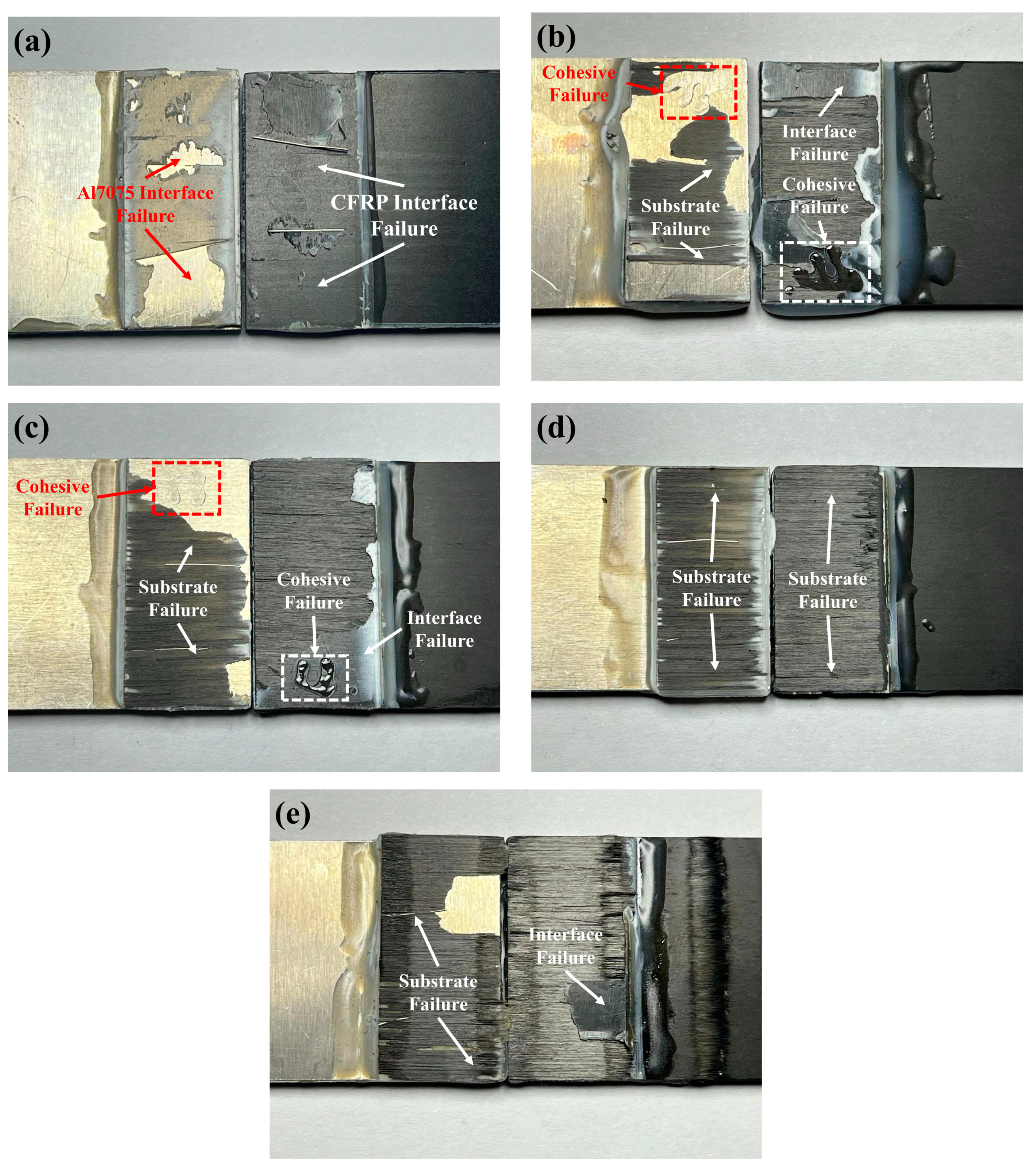
The typical failure modes of adhesive joints are primarily categorized into three types: substrate failure, interface failure, and adhesive failure. Under normal circumstances, adhesive joints can exhibit two or more failure modes, known as mixed failure. The different failure modes observed reflect the strength relationships between the substrate, adhesive, and interface [
25].
Among the three failure modes, substrate failure is an ideal failure mode because it signifies that the adhesive bonding strength exceeds that of the substrate itself. This indicates that the adhesive bonding strength meets the required standards. Cohesive failure refers to separation within the adhesive layer itself, indicating that the adhesive’s strength is lower than the interface bonding strength between the adhesive and the substrate. Interface failure refers to separation between the adhesive and the substrate at the bonding interface. If interface failure occurs in a joint, it typically indicates lower strength.
The failure modes of CFRP/Al7075 adhesive joints with different LTP surface treatment distances are shown in
Figure 7.
Figure 7 shows that the failure mode of the untreated group joint is interface failure. In this case, the interface bonding strength between CFRP and the adhesive is weaker than that of Al7075, resulting in lower shear strength of the joint. At a distance of 20 mm, larger areas of CFRP substrate failure, as well as small areas of interface failure and cohesive failure, begin to appear on the fracture surface. This indicates that after LTP surface treatment, the interface bonding strength between CFRP and the adhesive is significantly improved. Consequently, the shear strength of the joint is substantially increased. At a distance of 15 mm, the area of CFRP substrate failure increases further, and the shear strength of the joint continues to increase as well. At a distance of 10 mm, the fracture surface shows complete CFRP substrate failure, and the shear strength of the joint reaches its peak. At a distance of 5 mm, there is also extensive CFRP substrate failure on the fracture surface. However, at this distance, the damaged CFRP surface exhibits severe burn marks, indicating that LTP has had a significant negative impact on the performance of CFRP itself. This also explains the sudden decrease in the shear strength of the joint.
In general, the changes in the failure mode of the joint correspond closely to the changes in the shear strength of the joints. LTP surface treatment primarily improves the bonding properties of the joint by enhancing the interface bonding strength between the CFRP surface and the adhesive.
3.4. Surface Wettability Analysis
Research has shown that the type of liquid, the microstructure, and the surface free energy of the material, as well as different interfaces, can all influence the wettability of materials. Composites with good wettability have a higher ability to be infiltrated by adhesives, resulting in the formation of high-strength bonding interfaces [
26,
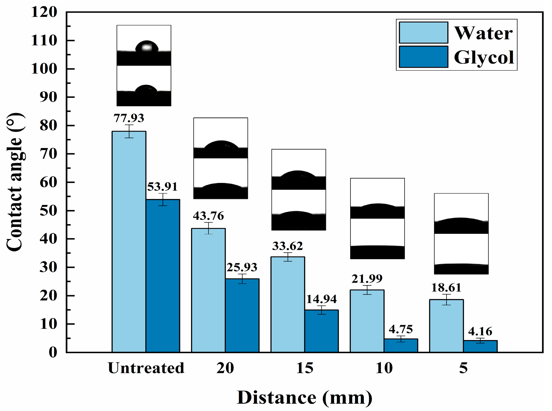
27]. Therefore, in this study, the contact angles of CFRP surfaces with water and glycol were measured to characterize the surface wettability of CFRP.
The contact angles between the CFRP surface and water and glycol at different LTP surface treatment distances are shown in
Figure 8.
From
Figure 8, it is evident that the contact angles between the CFRP surface of the bank group and the two test liquids are relatively large. However, after undergoing LTP surface treatment, there is a significant decrease in the contact angles of the CFRP surface. As the distance decreases, the reduction in contact angles becomes gradually smaller. When the distance reaches 10 mm and 5 mm, the contact angles remain nearly constant.
According to the Owens-Wendt-Rabel-Kaelble method [
24], the dispersion component, polar component, and total surface free energy of the CFRP surface at different LTP treatment distances are calculated, as shown in
Figure 9.
The surface free energy of polymers is primarily composed of polar and dispersion components. The polar component refers to the energy of interaction between polar molecules on the material surface, while the dispersion component refers to the energy of interaction caused by the instantaneous dipoles of the surface molecules (van der Waals forces). Changes in the polar and dispersion components reflect variations in the surface chemical activity of the material [
28].From
Figure 9, it can be observed that the dispersion component of the CFRP surface in the untreated group accounts for a higher proportion of the total surface energy, and the total surface energy is low. After LTP surface treatment, the polar component of the CFRP surface significantly increases, while the dispersive component slightly decreases. As a result, the total surface energy of CFRP experiences a significant increase. As the distance decreases, the proportion of the polar component in the surface free energy of CFRP increases, while the dispersive component continues to decrease. After reaching a distance of 10 mm, the magnitude of the increase in the polar component diminishes significantly, and the surface free energy no longer shows a noticeable improvement. This indicates that there is a saturation point for the improvement of surface wettability of CFRP by LTP surface treatment. Once the surface wettability of CFRP reaches this saturation point, further reduction in distance will have no significant impact on the surface energy of CFRP.
3.5. Surface Morphology Analysis
According to the theory of mechanical interlocking, when an adhesive flows over the surface of a material, it diffuses and infiltrates into small pores on the surface, displacing any air present. Once the adhesive cures, a mechanical interlock is formed between the adhesive and the material surface. Therefore, the surface morphology of the material also has a significant effect on the bonding strength [
29]. The surface micromorphology of CFRP with different LTP surface treatment distances is shown in
Figure 10.
Figure 10 shows that the surface of the CFRP in the untreated group appears smooth and flat, with good bonding between the fibers and the resin. There are also a few resin particles present on the surface. At a distance of 20 mm, the LTP surface treatment has caused a slight ablation on the CFRP surface, leading to the exposure of bare carbon fibers. Additionally, there is an increase in the presence of small granular resins. At a distance of 15 mm, the LTP surface treatment further deepens the ablation on the CFRP surface. In addition to the small granular resins, larger areas of pits are now appearing on the CFRP surface. At a distance of 10 mm, significant changes in the morphology of the CFRP surface are observed. Gully like textures are now distributed across the entire surface of the CFRP. At a distance of 5 mm, the resin on the surface of the CFRP undergoes more severe ablation, leading to localized fiber debonding on the outermost layer.
In general, when the LTP surface treatment distance is 20 mm or 15 mm, the ablation depth of the CFRP surface is not significant. The surface morphology remains relatively flat, showing minimal difference compared to the CFRP from the untreated group. At a distance of 10 mm, a significant change in the morphology of the CFRP surface occurs, resulting in gully like textures. These textures contribute to enhancing the mechanical interlocking between the adhesive and the CFRP surface, thereby resulting in the highest shear strength of the joint. At a distance of 5 mm, the LTP surface treatment reaches a critical point for the ablation of CFRP. At this point, the resin is severely ablated, and localized fiber debonding occurs, resulting in a significant decrease in the shear strength of the joint.
3.6. Surface Chemical Structure Analysis
Research has shown that the excited-state radicals present in LTP carry a significant amount of energy, capable of breaking any organic chemical bond. Through LTP surface treatment, a series of complex grafting and crosslinking reactions occur on the CFRP surface, leading to changes in the surface’s chemical structure. The fracture of certain organic bonds in CFRP generates new reactive groups, thereby enhancing the surface’s chemical activity [
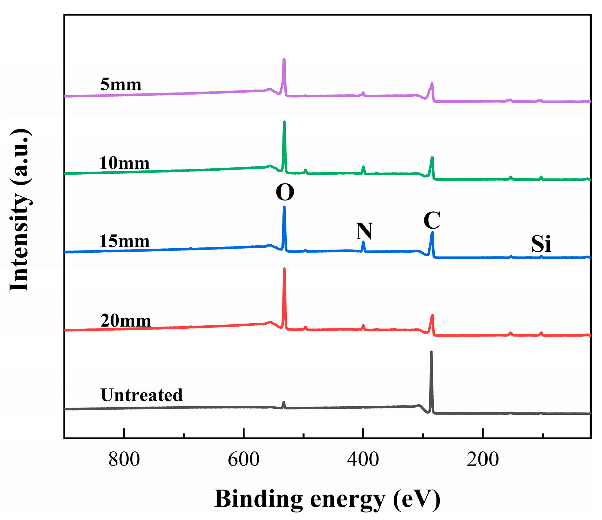
17]. The relative elemental content and XPS wide-scan spectrum of CFRP surfaces with different LTP surface treatment distances are shown in
Table 10 and
Figure 11.
Based on
Figure 11, it can be seen that the surface of the control group’s CFRP primarily consists of carbon, and the content of nitrogen and oxygen is relatively low. After LTP surface treatment at a distance of 20 mm, the oxygen content on the surface of CFRP significantly increases, while the nitrogen content also shows a slight increase. As the distance decreases, the oxygen-to-carbon ratio shows a continuous increase, while the nitrogen-to-carbon ratio does not show significant changes. This indicates that changes in the LTP surface treatment distance primarily affect the content of oxygen-containing functional groups on the surface of CFRP, while having a minimal impact on nitrogen-containing functional groups. At the same time, the silicon content on the surface of CFRP with different LTP surface treatment distances exhibits an irregular variation trend, which may be related to the use of silicon-containing release agents during the CFRP fabrication process.
The results of C1s peak fitting of CFRP with different LTP surface treatment distances are shown in
Figure 12. The black scattered points in the figure represent the raw data, the red curve represents the fitted curve, and the gray curve represents the baseline. The absorption peaks of different functional groups are represented by curves of different colors.
The results of the C1s peak fitting indicate that the oxygen-containing radicals in LTP primarily react with the C=C and C-C groups on the surface of CFRP, resulting in the formation of oxygen-containing functional groups such as C-O, C=O, and C-C=O. After the LTP surface treatment, the C=C groups on the surface of CFRP in the untreated group disappear and are converted into oxygen-containing functional groups. Furthermore, as the distance decreases, the C-C groups also continuously react with oxygen-containing radicals, leading to the generation of oxygen-containing functional groups. This continuous reaction process increases the oxygen-to-carbon ratio on the surface of CFRP.
The relative content of C1s groups on the surface of CFRP with different LTP surface treatment distances is shown in
Table 11.
According to
Table 11, it is evident that the types and quantities of C1s functional groups on the surface of CFRP undergo changes with different LTP surface treatment distances. The LTP surface treatment primarily increases the content of oxygen-containing functional groups on the surface of CFRP. As the treatment distance decreases, the oxygen-containing radicals continuously react with the C-C groups, leading to the formation of oxygen-containing functional groups. The proportion of polar functional groups to non-polar functional groups on the surface of CFRP increases from an initial value of 0.07 to 2.85. This significant increase in the ratio indicates a substantial improvement in surface chemical activity.
Overall, LTP surface treatment significantly improves the surface chemical activity of CFRP. As the distance decreases, the proportion of oxygen-containing polar functional groups on the surface of CFRP continuously increases. This enhancement effectively improves the surface energy and wettability of CFRP, ultimately leading to improved interface bonding properties with adhesives.


