
A Review of Cross-Scale Theoretical Contact Models for Bolted Joints Interfaces
College of Nuclear Science and Technology, Naval University of Engineering, Wuhan 430030, China
*
Author to whom correspondence should be addressed.
Coatings 2024, 14(5), 539; https://0-doi-org.brum.beds.ac.uk/10.3390/coatings14050539
Submission received: 25 March 2024
/
Revised: 21 April 2024
/
Accepted: 23 April 2024
/
Published: 26 April 2024
(This article belongs to the Special Issue Friction and Wear Behaviors in Mechanical Engineering)
Abstract
:Bolted joints structures are critical fastening components widely used in mechanical equipment. Under long-term loading conditions, the bolted joints interface generates strong nonlinearities within the system. The nonlinear stiffness inside the bolt leads to changes in the stiffness of the whole system. This affects the dynamic characteristics of the whole system. It brings challenges and difficulties to the performance prediction and reliability assessment of the equipment. A cross-scale theoretical model study based on the microscopic contact mechanism can provide a more comprehensive understanding and cognition of the degradation behavior of bolted joints interfaces. The current development status and deformation process of asperity models are summarized. The research progress of statistical summation model and contact fractal model based on microscopic contact mechanism is analyzed. The experimental methods for parameter identification of connection interfaces are reviewed. The study of numerical modelling of bolted joints structures from the surface contact mechanism is briefly described. Future research directions for cross-scale modelling of bolted joints structures are outlined.
1. Introduction
Bolted joints structures are key fastening parts and connecting units that are widely used in mechanical equipment. The bolted joints structure plays an important role in connecting various parts and transferring loads in the complete piece of engineering equipment. At the same time, bolts have the advantages of easy disassembly and high reliability. However, as the bolted joints structure is subjected to long-time loading conditions, its connection interface will cause the system to generate strong nonlinearities. At the same time, there is additional energy dissipation. This causes changes in the stiffness of the whole system, thus affecting the dynamics of the whole system [1]. Wu and Zhu [2] analyzed the modeling method of bolted joints structure in modal calculation by finite element method, which provided theoretical support for the dynamic analysis of bolted joints structure.
Existing equivalent linearized connection structure dynamics analysis meets most of the engineering needs, but there are problems due to experimental conditions or model parameters calibration under the premise of the difficulty of extrapolation. It is difficult to explain the corresponding mechanism of nonlinear dynamics of the internal contact behavior of the connection structure, so, for the bolted joints, structural connection interface of the research is of great significance.
The general schematic diagram of the bolt joints structure of complex equipment is shown in Figure 1. Its connection interface is the bolded part of the figure. When the connection structure is subjected to the tensile load applied from both sides, the connection interface will have a stick zone and a slip zone. The mechanical friction microscopic contact model of its connection interface is shown in Figure 2. When the bolted interface is subjected to normal contact load, there will be normal damping characteristics and normal contact stiffness; when subjected to tangential load, tangential damping characteristics and tangential contact stiffness will be generated [3]. Jin Jing et al. [4] proposed a method of using local cooling and equivalent friction to jointly load the prestressing of a bolted joints structure, which simulated the distribution of stress in the pretensioned bolted joints structure. They provided a new method for the simulation of bolted joints structure.
Many scholars have conducted a lot of work on the contact characteristics of this connection interface. The key problems in the study of bolted joints structures lie in how to accurately represent the contact slip mechanism of rough surfaces, how to establish nonlinear models corresponding to different mechanical behaviors at the connection interface, and how to calculate the complex nonlinear mechanical problems at the interface of the connection structure.
To solve these three problems, most of the scholars who study bolted joints structures most commonly use the following two technical routes. One type of modeling is “top-down” modeling from experimental phenomena. This is in the form of an abstract mathematical model with nonlinear system identification methods to study the effect of connecting interfaces on structural dynamics. Using this route, the parameters in the mathematical model are determined. The top-down modeling is usually an image-only model, and common models [5] include the Iwan model, Lugre brush model, and Valanis model. The models are shown in Figure 3.
The other is a “bottom-up” modeling approach that starts from the microscopic contact mechanism. This method starts from the analysis of the contact behavior of a single asperity for forward modeling. The entire rough contact surface is then analyzed using statistical summation or contact fractal modeling. In turn, an intrinsic model that can reflect the mechanical characteristics of the contact is established from the microscopic contact mechanism. The model is mainly divided into contact fractal model and statistical summation model.
With the in-depth study of bolted joints structures, scholars at home and abroad have found that there are contact mechanical characteristics of the connection interface at different scales. As such, they gradually carry out the cross-scale study of the connection structure. The “cross-scale” of bolted joints structures is mainly reflected in the following two parts.
- The characteristic lengths of bolted structural components are usually in the order of 100 to 101 m, the scale of the connection structure is usually in the order of 10−2 m, and the scale of the asperity of the actual rough surface of the connection interface is usually in the order of 10−5 to 10−6 m.
- The time to reach the steady-state response of complex equipment under dynamic loading is typically on the order of 100 to 101 s, while the time step describing the slip behavior of the bonded surfaces is on the order of 10−9 s.
For cross-scale studies, most of the current studies adopt the “bottom-up” approach to establish the intrinsic model.
This “top-down” modeling approach describes the energy dissipation and damping characteristics of connected structures. One such model, the Iwan model [6], can be represented as a model with N Jenkins cells side-by-side, as shown in Figure 4. All spring coefficients are the same and equal to k (k1, k2… kN). The slider has no mass and is subjected to a normal force FPi. The subscripted letter I indicates the index of the slider, ranging from 1 to n. The fork symbol on the slider indicates the direction of the normal force. All coefficients of friction between the sliders and the plane are the same, denoted by m. Therefore, the critical friction fi* that causes sliding for each slider can be calculated as follows:
The model is capable of determining the hysteresis lines obtained from tangential loading, unloading, and reloading of bolts. The model is also able to accurately characterize the nonlinear dynamics of microscopic and macroscopic slips of bolted joints by means of a power relationship for energy dissipation and a six-parameter density function for the residual stiffness phenomenon. The six-parameter density function of the residual stiffness phenomenon can be accurately obtained from the six-parameter Iwan model by means of, among other things, the bone-line equation. This function clearly and accurately characterizes the nonlinear dynamics of microscopic and macroscopic scale slips in bolted joint structures. However, it is difficult to explain the nonlinear dynamics response mechanism of the contact behavior inside the connection by this method [7].
Figure 4.
Schematic of the Iwan model [6].
Figure 4.
Schematic of the Iwan model [6].

The “bottom-up” modeling approach can be used to establish the mechanical model of the rough connection interface of the connection structure based on the influence of the micro- and micro-contact mechanism of the rough surface and the morphology features. Micro-scale modeling of rough surfaces is an important method to reveal the degradation mechanism of the joint structure. At the microscopic roughness scale, the static-dynamic characteristics of bolted joint interfaces can be better described and analyzed from the internal contact mechanism and geomorphic features of the bond surface. However, the accuracy of the model is affected by factors such as surface geomorphologic parameters. Therefore, cross-scale modeling of bolted interfaces in complex equipment has strong research needs and research significance.
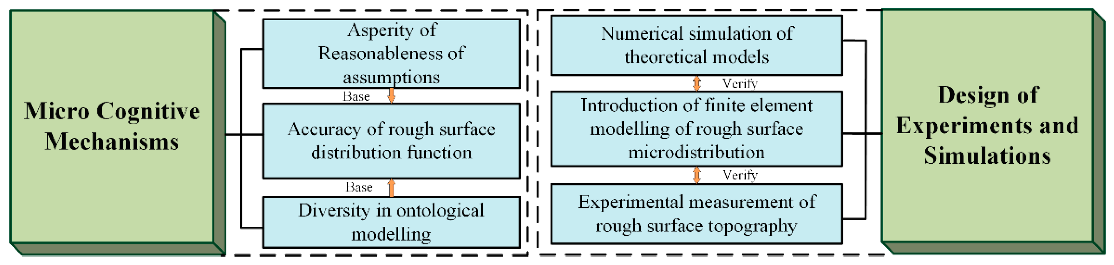
The purpose of this paper is to understand and study more comprehensively the connection interface of the whole bolted joint structure. This paper focuses on the asperity theory model, the contact fractal model, as well as the statistical summation model and the interface experimental parameter identification method. The current research status of cross-scale modeling of the connection interface of complex equipment bolted connection interfaces on the microscopic amorphous scale is reviewed and analyzed. The difficulties in building cross-scale models are Micro Cognitive Mechanisms and Design of Experiments and Simulations. The main part of the full text is also shown in Figure 5.
2. Body
2.1. Theoretical Modeling of Asperity
The problem of contact interface of connecting structure is actually the contact problem between two rough surfaces. On the macro level, the contact problem between two rough surfaces is mainly affected by the contact mode of the two surfaces, the form of load, and the material properties; on the micro level, the nature of the contact between two rough surfaces is the mutual contact between the two surfaces, the deformation stage of the asperity, stress-strain relationship, and the material properties of the asperity, all of which need to be considered as a key point of the asperity contact. Therefore, the basic problem of contact mechanics is the elastic-plastic contact between spherical or aspherical asperities on rough surfaces under tangential or normal loads. To better explain the contact mechanism between two rough interfaces in the microscopic view, it is crucial to establish a suitable theoretical model of asperities. Currently, the two most common assumptions are the smooth plane assumption and the interaction assumption:
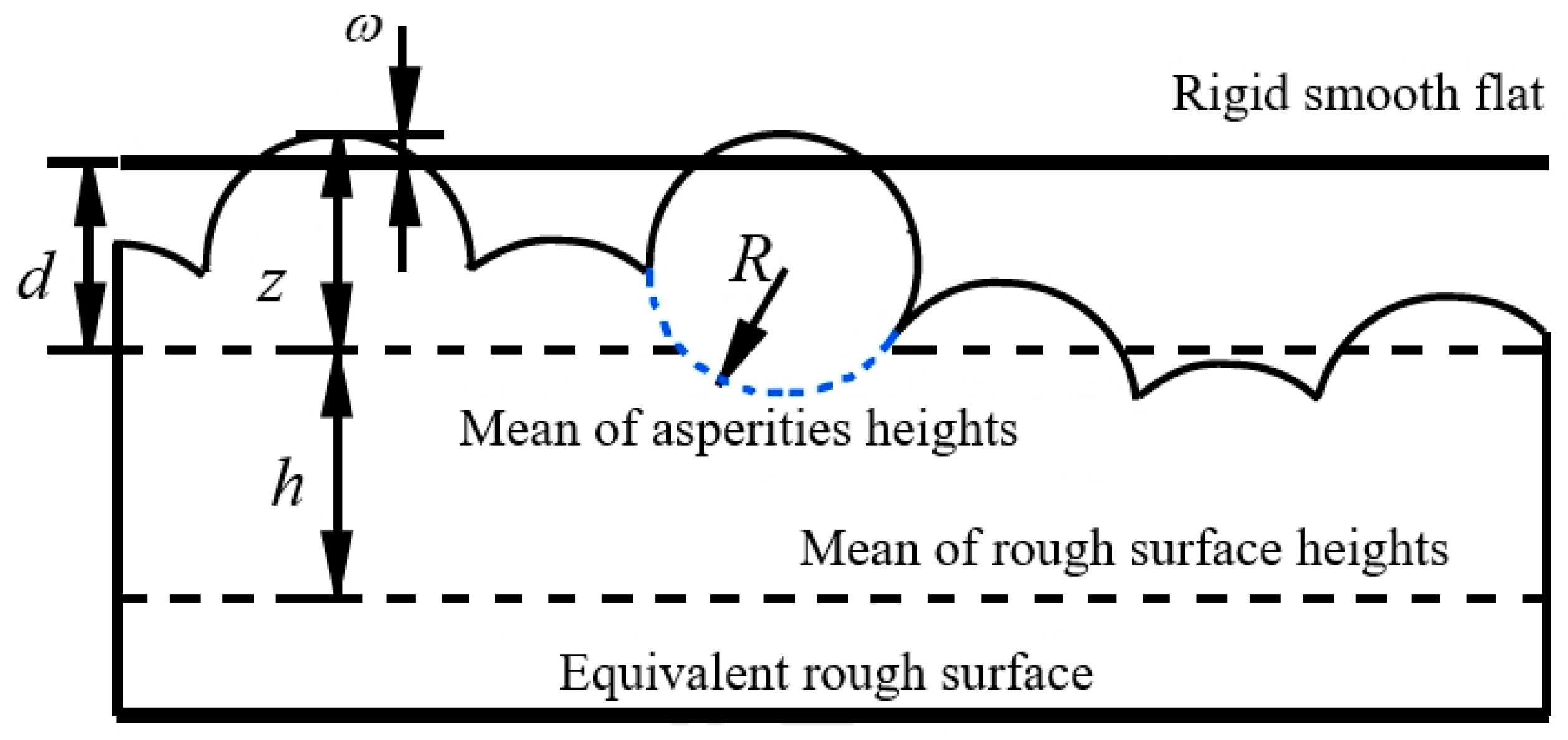
The smooth plane assumption assumes that the contact between the asperity and a smooth rigid flat plate is carried out, and the elastic-plastic changes and contact mechanical characteristics of the asperity subjected to normal and tangential loads are analyzed, as shown in Figure 6.
The interaction assumption assumes that the two asperities on the upper and lower surfaces are in contact with each other. Both asperities are deformed under normal load, which is categorized into peak-to-peak contact and side contact, as shown in Figure 7.
Hertz [9] was the earliest researcher of contact problem. In 1881, Hertz proposed “Hertz contact”, which analyzed and theoretically solved many common elastomeric contact stresses. In Hertz’s elastic contact theory, Hertz derived the analytical solution for the elastic contact of two arbitrary surfaces. According to the classification in the Hertz contact theory, the theoretical model of the asperity can be obtained: the rough surfaces in contact with each other are composed of a large number of asperities. The asperities on the two rough surfaces are regarded as elastic spheres. The asperities undergo the corresponding deformation and generate stress when the two surfaces are in contact, so as to obtain the relationship equations between the contact load F, the contact area A, the average base pressure P, and the amount of deformation δ as follows:
where E is the composite modulus of elasticity, is Poisson’s ratio, and δc is the critical contact deformation.
In order to satisfy the conditions for the theoretical solution, the Hertzian contact theory contains a number of assumptions to facilitate the characterization of the contact properties of asperities:
- (1)
- The material of the asperity is assumed to be uniformly distributed and isotropic.
- (2)
- It is assumed that the material of the asperity produces only minor deformations of full elasticity.
- (3)
- Consider only the stresses of a single asperity and do not consider the effects of other neighboring amorphous bodies in the same plane.
- (4)
- A single asperity is subjected to normal contact loads only, without considering friction between rough surfaces. After the emergence of Hertz contact theory, due to its simple and practical characteristics, many scholars have used the theory to simplify the calculation. Based on Hertz’s theory, the contact model has evolved from the initial consideration of only the elastic deformation stage of spherical asperities to the present more complex contact model that considers many surface morphology characteristics and material parameters. Material parameters mainly contain friction energy loss, asperity geometry and size, asperity interaction, substrate deformation, hardening of the material, surface adhesion, non-uniform distribution of load, scale effect of the mechanical behavior of the material, and horizontal distance of the surface asperity. This large number of considerations needs to take into account the continuous deformation process of the asperity, so the theoretical models for the cases of fully elastic, fully plastic, and elastoplastic deformation of the asperity are gradually improved.
2.1.1. Theoretical Modeling of Fully Elastic and Fully Plastic Deformation Stages of Asperities
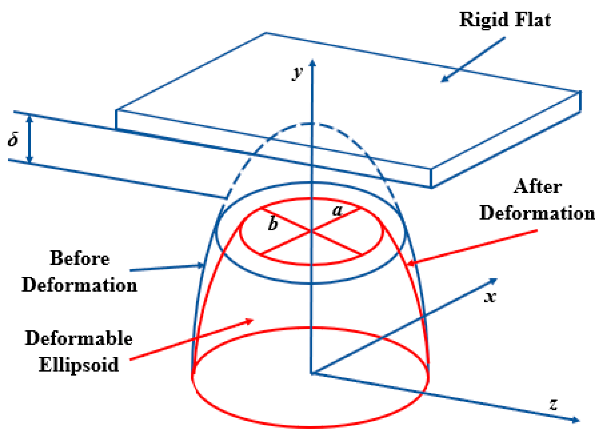
Hertz’s theory is the basis of classical contact mechanics. His theoretical model of asperity includes the relationship between the load on asperity and the amount of deformation and radius. Here, however, the deformation of asperity is small and fully elastic. When the deformation reaches a certain value, asperity deforms plastically. The constraint models for the elastic and plastic phases are completely different. The stress-strain relationship in the fully elastic stage is the linear one, while most of the cases in the fully plastic stage are nonlinear. The elastic and plastic phases have completely different constitutive models; the stress-strain relationship in the fully elastic deformation phase is linear, while most of the cases in the fully plastic deformation phase are nonlinear. Many scholars base their work on Hertz’s contact theory. The fully elastic deformation stage and the fully plastic deformation stage of the asperity are theoretically modeled. The fully elastic deformation stage and fully plastic deformation stage of the amorphous body after being subjected to tangential or normal load were investigated. All the studies aim at a more comprehensive and accurate characterization of the contact state between rough contact surfaces. This greatly enriches the study of amorphous properties at contact interfaces. Hertz used an analytical solution to obtain an intrinsic model of the asperity. Hertz regarded the asperity as a contact between two spheres. Jung Ching Chung regarded the shape of the asperity as an ellipsoid and gave a finite element model of the equivalent nonstress and displacement formed when an ellipsoid of different ellipticities on an ideal elastic-plastic material is in contact with a rigid plane; this established a theoretical model of the contact between an ellipsoid and a rigid flat plate [10], which is shown in Figure 8. Jung Ching Chung used a finite element and numerical solution to obtain an intrinsic model of the asperity.
Kogut and Etsion [11] analyzed a sphere subjected to a rigid plane load that undergoes fully elastic and fully plastic deformation by means of finite element method and found the maximum tangential load present on the surface of the asperity at the onset of sliding. Kogut concluded that the occurrence of sliding on the rough surface is a destructive mechanism due to plastic deformation of the asperity that yields, which leads to the occurrence of slipping, rather than slip based on the coefficient of friction. The “coefficient of internal static friction” is defined, and a simple analytical equation is given for both elastic and plastic cases. Kogut and Etsion used a semi-analytical method with finite elements and solved analytically to obtain an intrinsic model of the asperity.
Halling and Nuri [12] elaborated on the importance of plasticity indices for determining the degree of elastic-plastic deformation of surface projections. This argument is validated experimentally, and the methodology is extended to the ellipsoidal roughness contact case and to the effect of work-hardening under a general roughness height probability distribution. The paper also shows how the model can be applied to the study of the properties of multiphase composites. The arguments are based on Hertzian contacts without traction but can be made with reasonable confidence for contacts with friction coefficients less than 0.1. Wang et al. [13] argued that for micro- and nano-scale contact problems, the effect of surface tension is particularly prominent. On the basis of solving the point force on an elastic half-space with surface tension, the contact equations for a rigid ellipsoid and an elastic substrate are given. The modeling approach adopted is to consider the asperity as a rigid ellipsoid and the boundary in contact as a perfectly elastic material. The corresponding singular integral equations are solved numerically by Gauss–Chebyshev integral formulation. When the size of the contact region is comparable to the length of the elastic capillary, surface tension significantly alters the distribution of the contact pressure and reduces the contact area and indentation depth compared to the classical Hertz’s prediction. Explicit expressions for the equivalent contact radius, indentation depth, and contact ellipse eccentricity with respect to the external load are generalized, providing a basis for analyzing nanoindentation tests and contact on rough surfaces. Nuri and Wang used the method of solving the analytical solution to obtain the intrinsic model of the asperity.
Based on the Hertz contact theory, the above scholars have established different geometries and rigidity assumptions of the asperity model to better study the contact characteristics of the asperity in the case of small deformation of the fully elastic body. However, it is not possible to fully describe the contact mechanism of the contact surface by only studying the contact characteristics under small deformation. Therefore, some scholars, on the basis of Hertz’s theory, assumed that the asperity’s material is an ideal elastic-plastic material, and developed the theoretical model of asperity in the perfectly elastic stage and perfectly plastic stage, which describes the mechanical properties of the asperity more comprehensively and more accurately.
Greenwood and Williamson [14,15] proposed a new elastic contact theory based on the Hertz theory, which is more closely related to the actual surface than previous theories, and demonstrated the effects between surface topographic features (the distribution of asperities and the radius of curvature of the asperities) and contact deformation as well as loading. Greenwood and Williamson used the method of solving the analytical solution to obtain the intrinsic model of the asperity. A criterion for distinguishing between elastic and plastic contact surfaces is established, and a new contact model, the GW contact model, is developed. The theory also points to the existence of an “elastic contact hardness”, a general hardness value that expresses the ability of a material surface to resist the plastic deformation induced by the indentation of another object, whereas the GW model proposes that this composite quantity, which applies during the elastic deformation phase and depends on the elastic properties and morphology, plays the same role in elastic contact as the conventional hardness does in plastic contact. Greenwood and Williamson also created a new surface measurement system consisting of an analog-to-digital kernel sampling unit acquisition computer that can experimentally measure surface voltages to measure the parameters that characterize rough surfaces in theoretical models, as well as the radius of curvature of asperities. These data measured by the system have revealed that contact between surfaces is usually plastic. Greenwood and Williamson have been able to study the distribution of roughness heights and other surface characteristics for a variety of surfaces prepared by standard techniques. It is usually assumed that the actual area of contact between two nominally flat metal surfaces is determined by the plastic deformation of their highest projections. This immediately leads to the conclusion that the actual contact area is proportional to the load and is independent of the surface contact area. Ciavarella et al. [16] improved the GW elastic contact model by considering the interaction of the asperities, while the model did not consider the elastic-plastic deformation phase of the asperities. Archard [17] pointed out that plastic deformation cannot be the universal law and introduced a model that showed that, contrary to earlier beliefs, the contact area may be proportional to the load even in purely elastic contact. When the normal contact load increases to a certain point, the Hertz small deformation solution will no longer be validly applicable, at which point the maximum shear stress of the material reaches a critical value and the contact deformation will begin to appear plastic [18]. To study the plastic deformation process of the asperity, Abbott and Firestone created a plastic contact model between rough surfaces, referred to as the AF model [19]. Plastic and elastic contacts use completely different constitutive models; the size of the contact area is not the same, the plastic contact area is twice as large as the elastic contact area, and the AF model clearly reflects the influence and expression of the average contact pressure and contact load. Ishlinskii [20] analytically investigated the average contact pressure of the asperity at the stage of complete plastic deformation, and the average contact pressure of the asperity was 2% of the equivalent force. The average contact pressure of the asperity is 2.8 times the equivalent force. Tabor [21] found that during the deformation of the material, when the fully elastic phase ends there is a yielding phase, which changes to a fully plastic deformation phase, in which the contact radius and contact load of the asperity increase exponentially. Matthews [22] found that in the phase of fully plastic deformation, creep dominates, and deformation occurs only in the vicinity of the contact surface. Chang et al. [23,24,25] proposed the classical CEB model to establish the critical contact volume for the transition between the fully elastic deformation stage and the fully plastic deformation stage. All the above scholars have analyzed the mechanical properties of asperities in the fully elastic and fully plastic stages based on the Hertz elastic contact theory to create a theoretical model of asperities. All used the method of solving the analytical solution to obtain the intrinsic model of the asperity. However, the deformation process of the material is the existence of a transition stage from elasticity to plasticity; the CEB model only establishes the critical points of fully elastic and fully plastic and does not theoretically model the contact of the asperity throughout the elastic-plastic transition stage. The theoretical modeling about the asperity still needs to be studied and analyzed for the elastic-plastic deformation stage.
2.1.2. Theoretical Modeling of the Elastic-Plastic Phase of Asperities
Zhao et al. [26] proposed an elastic-plastic contact model for the asperity in two nominal planar contacts and established a transition model for the asperity on the rough contact surface from fully elastic deformation to fully plastic, referred to as the ZMC model. The average contact pressure and deformation of the asperity as well as the contact area and deformation of the rough surface are modeled by logarithmic and fourth-order polynomial functions in the elastic-plastic deformation state. The computational results show that the ZMC model is more complete in describing the rough surface contact compared with the GW model and the CEB model. It also implies that the development of the theoretical model for the elastic-plastic stage of the asperity is very important.
Kogut and Etsion developed the KE model [27], which is a finite element simulation of a sphere in elastic-plastic contact with a plane. The contact model of the asperity in the fully elastic phase, elastic-plastic transition phase, and fully plastic phase is obtained from the simulation. The whole elastic-plastic phase in the model is divided into two phases, i.e., elastic-plastic phase I and elastic-plastic phase II. The KE model expresses the relationship between the contact load, area, average contact pressure, and deformation of the asperity at the two phases in the form of a segmented power-exponential function. The KE model makes all the deformation phases connected as a whole, which is more accurate and realistic compared with the CEB and ZMC models. They used a finite element and numerical solution to obtain an intrinsic model of the asperity.
Jackson and Green [28] also analyzed the elastic-plastic hemispherical contact problem by means of finite elements and established a hemispherical elastic-plastic contact model, i.e., the JG model. They used a finite element and numerical solution to obtain an intrinsic model of the asperity. Jackson’s results show that when the contact deformation is very small, the result is very close to the theoretical solution of the Hertz contact. When the contact deformation is too large, the result is not the same as the full plastic contact of the AF model. According to the finite element simulation, it is easy to find that in the elastic-plastic contact deformation stage, the JG contact model is closer to the simulation results than the KE model and the ZMC model. The JG model can effectively study the contact behavior of the asperity. The model is also adaptable to macroscopic contact.
Brake et al. [29,30] used the Von Mises yield criterion and Brinell hardness to determine the amount of elastic-plastic deformation and plastic deformation of the asperity. Brake interpolated the elastic-plastic contact phase using Hermit polynomials to find the relationship between the contact area and the average contact pressure and deformation of the elastic-plastic phase.
Zhao et al. [31] improved his own ZMC model and proposed a new elastic-plastic micro contact model based on his original model. The model is based on the fact that the transformations between the elastic, elastoplastic, and plastic phases are continuous and smooth throughout the deformation process. The model has a larger actual contact area and smaller normal distance for the same plasticity index and loading conditions. As the plasticity index increases and the load increases, the gap between this model and other models increases.
Xu and Wang [32] used a modified Hermit interpolation method to fit the curve to the elastic-plastic deformation stage. The method enhanced the continuity and smoothness of the whole curve at the critical deformation. He modeled the entire contact interface based on the analytical approach of the GW model. The deformation and the elastic-plastic contact area results are not uniform and contradictory in this model because of the interpolation.
Based on the theory of continuous media, Chen et al. [33] argued that the deformation and force of an asperity at any stage should be smooth, continuous, and monotonic. He established an elastic-plastic contact model based on the exponential function through the mode of the first-order system step response function. The model can well solve the feature that the functions of pressure and deformation of the asperity are not smooth and continuous at different stages. However, while the model solves the discontinuity of the demarcation point, it is also characterized by a large error in the curve of the whole elastic-plastic stage. Wang et al. [34] also established a new microscopic contact model to address the phenomenon of discontinuity and non-smoothness between different stages of asperity. It fitted the new relational curves of elastic-plastic deformation stages by the improved Hermit interpolation method, which transforms the relevant physical quantities such as contact loads into logarithmic coordinates. By comparing the CEB model, the ZMC model, and the KE model, the relationship between the plasticity index and the average deformation is obtained. The elastic-plastic phase is mostly studied by means of the finite element method and finding numerical solutions.
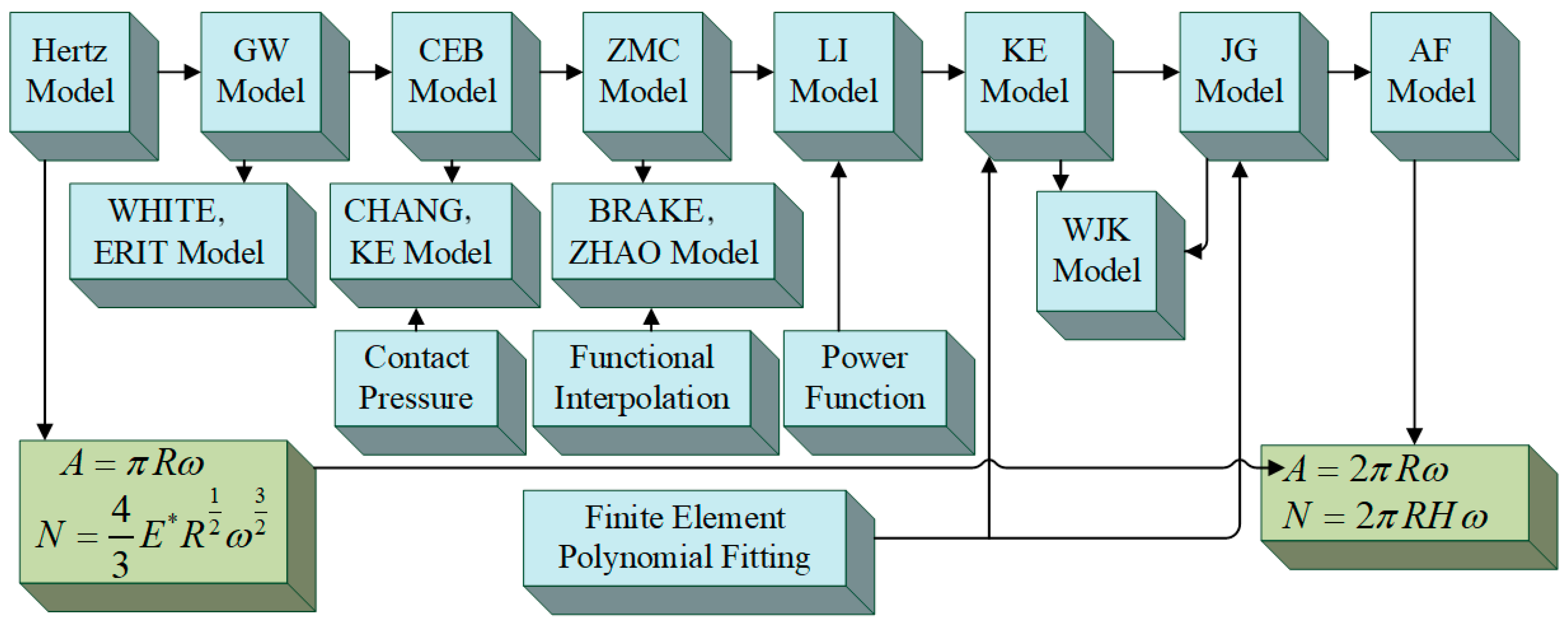
The above scholars have done a lot of research on the contact characteristics of asperities. The most widely used ones include KE model, ZMC model, CEB model, and the contact model established by Chao Xu and Dong Wang through the interpolation method. The current typical elastic-plastic model is shown in Figure 9.
In addition to the theoretical model of the deformation stage of asperities, Zhang et al. [35] also investigated the wear mechanism of rough surfaces in contact with each other. Zhang reviewed and analyzed the mechanical properties of the contact interface from the perspective of asperity wear, as shown in Figure 10. They suggested future work to consider more realistic geometries and material properties for modelling contact wear.
The contact deformation of asperities was also described by Li Biao et al. [36] when they conducted a review of contact mechanics in tribological and contact damage-related problems. Li Biao et al. also systematically described the application of contact mechanics in various problems.
Bhushan [37] presents a comprehensive and systematic introduction to the analytical solution of surfaces with well-defined height distributions and asperity geometries. He also presents a comprehensive and systematic overview of numerical solutions for surfaces with well-defined height distributions and asperity geometries. His review nicely summarizes and generalizes the research methodology for 3D modelling of rough surfaces.
Salari and Beheshti [38] have summarized and generalized the current state of research on contact mechanics of rough surfaces from the creep point of view. Their review details the deformation effects of a single asperity when subjected to normal and tangential loads. Numerical calculations under combined loading are usually only possible for small deformations. It is difficult to converge numerically for large deformations in contact.
Flores [39] provided a comprehensive review of contact mechanics for dynamical systems. The review considers regularized and non-smooth formulations and analyses the basic features of each method.
Tichy and Meyer [40] provide a comprehensive summary of the tribology of solid contact mechanisms. The frictional properties of rough surfaces are closely related to the mechanical properties of asperities.
Ghaednia et al. [41] devoted a summary to the current state of research on the elastic-plastic deformation phase of asperities. What is more remarkable is that the whole process from sticking to slipping of rough surfaces when loaded with tangential loads is summarized in that review.
The above model can visually describe the deformation process of elastic-plastic asperity when subjected to tangential or normal load. However, there are still cases where the critical points of elasticity and elastic-plasticity are not smooth and continuous in the model. The model is still unable to correspond well between the model of asperity and the actual mechanical properties of the interface.
2.2. State of the Art of Theoretical Modeling of Connectivity Interfaces
The contact characteristics of the connection interface of the bolted joints structure directly affect the static and dynamic characteristics of the whole connection system, while the static and dynamic characteristics of the connection structure will directly affect the mechanical characteristics of the whole complex equipment. Therefore, the study on the stiffness and damping characteristics of the connection interface is crucial, in which the establishment of a theoretical model on the connection interface is one of the important methods to study the interface parameters.
Scholars have carried out a lot of research on the theoretical modeling of contact stiffness and damping characteristics of contact interfaces, which mainly include statistical summation model and contact fractal model. Both of them are a kind of “bottom-up” modeling method through the theoretical modeling of the contact characteristics of the asperity, which is then combined with the material properties of the rough surface of the contact interface, the loading state, the asperity distribution law, surface roughness, and other nonlinear factors, to establish the corresponding theoretical model, then obtain the analytical model of the combined surface contact model, then obtain the preliminary solution of the theoretical model by simulation, and then combined with the actual material to obtain the theoretical model.
2.2.1. Statistical Summation Model
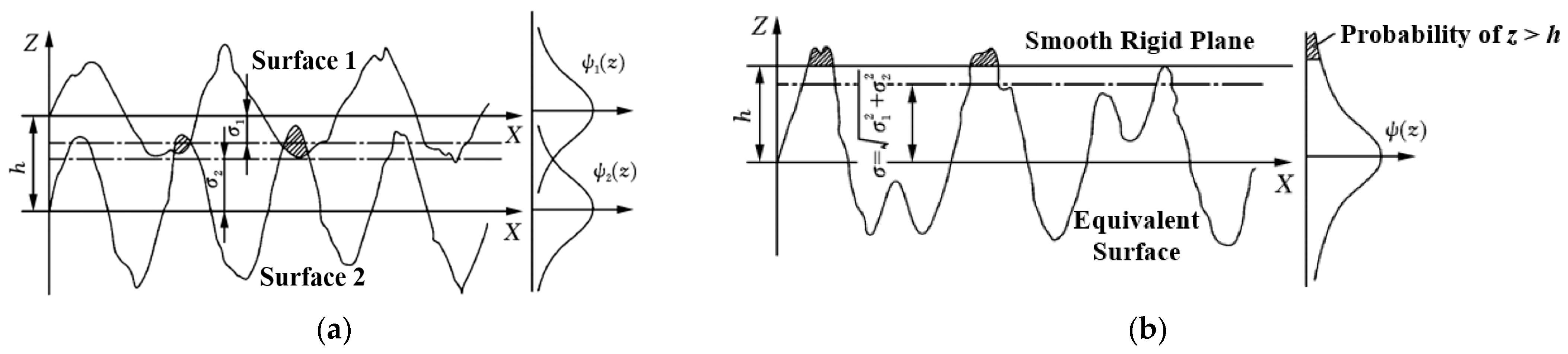
Assume that the rough surface consists of numerous asperities, each of which is a sphere with the same curvature. Based on the Hertz theory, the functional relationship between the load on a single asperity and the amount of penetration and contact area can be calculated. Assuming that the distribution of countless asperities on the rough surface is distributed according to a certain probability density function f(x), the contact behavior of all asperities is summed up by integrating, i.e., the relationship between the normal contact and deformation of the rough plane is obtained. Then the relationship between tangential force and tangential displacement can be obtained based on Cullen’s friction law, which is the statistical summation model.
The statistical summation model was first proposed by Greenwood and Williamson [14,15], and the analytical model of rough surface contact applicable to normal contact was established based on the method of statistical analysis. At the same time, the judgment basis for distinguishing between elastic and plastic contact surfaces was established. The GW model obtained the relationship between contact pressure, contact area, and deformation of rough surfaces by studying the heights of various asperities and the distribution of their surface features. The GW model is the first rough surface model that considers the curvature heights of the asperities on the rough surfaces as randomly distributed and statistically sums them up. After the GW model was proposed, Chang et al. [22] and others optimized and improved it by supplementing the statistical summation model with fully elastic and fully plastic models but did not consider the elastoplastic deformation stage. Zhao, Maietta, and Chang et al. [22] fitted to obtain the relationship equation between the average contact pressure and contact area of the asperity in the elastoplastic stage. Whitehouse and Archard [26] approximated the asperity height distribution as a Gaussian distribution and assumed the existence of autocorrelation at the material surface. By introducing the exponential function of autocorrelation, the joint distribution probability density function is established for the correlation between the height of the asperity and the radius of curvature of the peak. The WA model is established based on the GW model. Onions and Archard [42] optimized the assumptions in the distributions and performed a more in-depth study based on the joint distribution probability density function established in the WA contact model, establishing the OA contact model as a result.
Based on the Hertz contact theory, Tang et al. [43] investigated the influence mechanism of the asperity in the case of deformation of the substrate through the interaction assumption. Tang developed a theoretical model of contact mechanics for the bonding surface by statistical summation. Phan-thien [44] combined the GW model and Coulomb’s law of friction to develop a tangential contact mechanics model for rough surfaces and established the relationship between the tangential force and displacement relationship between tangential force and displacement. The model is based on the theoretical research framework of contact mechanics of the GW model. Mindlin [45] was the first to analyze the tangential contact behavior for the contact between smooth elastomers. Mindlin obtained the nonlinear relationship between tangential load and tangential displacement by analyzing the tangential micro-slip behavior when two smooth elastomers are in contact with each other with the expression as
where f is the friction coefficient of the contact surface, a is the radius of the circular contact area, T is the tangential load, is the relative displacement, G is the shear modulus, N is the normal load, and is the Poisson’s ratio.
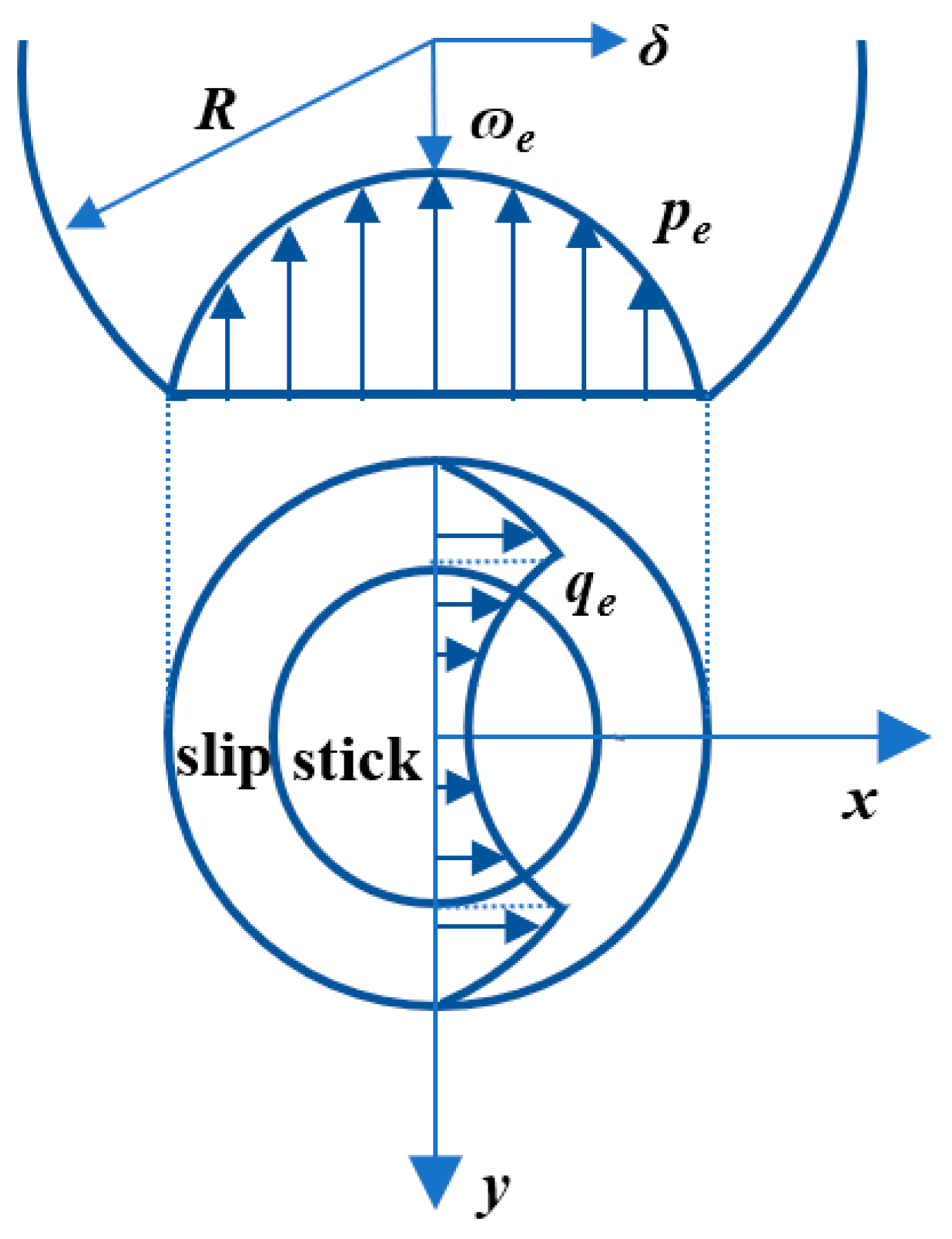
This is an extended study of the mechanical behavior of contact interfaces based on the idea of statistical summation. When the asperity undergoes elastic deformation, as in Figure 11, scholars have verified experimentally that microscopic slip behavior does exist in the tangential direction of the interface [46,47].
Jones [48] proposed a new tangential friction model for contact surfaces based on the GW model, which highlights the mechanical behavior of the contact surfaces before slip. Farhang [49] obtained the equations of the connected interface about the interface energy dissipation based on the nonlinear relationship between tangential load and tangential displacement obtained by Mindlin. He also solved the relationship between tangential force, tangential displacement, and interfacial energy dissipation through the approximation of the level expansion. The relationship between tangential force, tangential displacement, and interfacial energy dissipation is solved by level expansion approximation.
You and Chen [50,51] used a modified exponential distribution to replace the Gaussian distribution in the original GW model in response to the shortcomings of the existing statistical summation model. A new rough surface model was established for the static contact parameters of the rough surface under dry friction state by considering the fully elastic phase, elastic-plastic phase, and fully plastic phase. Kragelsky and Demkin [52,53] established a new model, referred to as the KD model. The model is to set the maximum height of the asperity on the rough contact surface as the reference height, assume that the random distribution law of the asperity is in the form of a power function, and use the difference between the height of the asperity and the reference height to correspond to the distribution of the asperity. Wang and Xu [54,55] established a new rough surface contact model by improving the KD model, assuming that the tangential slip behavior of the asperity exists and satisfies the solution of Mindlin’s equation. They proposed a stick-slip friction model of the bonding surface considering rough contact. The analytical form of the model is clear and simplified, and each parameter has corresponding physical significance.
Megalingam and Mayuram [56] and others measured and described asperities based on their various microscopic properties to derive mechanical expressions for asperities in contact. They proposed a new contact model for a single asperity: the MM model. The mechanical behavior of the whole rough contact surface is obtained by statistical summation, and empirical relations are fitted. The parameters in the contact process can be predicted by simulation, and a new contact model of the bonding surface obtained by the statistical summation method is obtained. Meanwhile, compared with other classical models, the KE model, JG model, and SM model [57] do not consider the elastic-to-plastic transition process and other properties and mechanical behaviors of the material, and only consider the Poisson’s ratio and its effect on the surface yielding. The MM model is a good complement to these models, providing the properties they do not have.
Xu et al. [58] developed a new statistical summation model within the framework of the simplified elliptic model of the GW model, the Nayak–Bush model [59,60,61,62], and the Greenwood model [63]. Most of the classical statistical summation models are only applicable to the early contact with small contact area, but not to the large contact with large deformation. The newly developed model can find the relationship between the non-contact area ratio and the average contact pressure as well as the average interfacial gap at near complete contact. The model has a wide coverage of contact area and is a generalized asymptotic solution model. Song et al. [64] developed a statistical summation contact model that is more in line with the actual test situation by considering the interaction between two rough surfaces with asperities. The relationship equation between contact area and average contact pressure was obtained from the contact model.
The statistical summation model can visualize the relationship between the contact parameters of a rough surface in contact. However, when verifying the accuracy of the statistical summation model, it is necessary to measure the topographic characteristics of the rough surface. Due to the different resolution and accuracy of the measuring instruments, the results of the statistical summation model are also different, which makes the results not unique.
2.2.2. Contact Fractal Model
Rough contact interfaces of connected structures have fractal characteristics such as cross-scale, disorder, irregular randomness, and self-similarity. If the connection interface is scaled up infinitely and repeatedly, the rough interface at each scale has similar distributional properties. The main distributional properties are manifested as multiscale and discontinuous, with mathematical features of non-differentiability and statistical self-affine [65], as shown in Figure 12. Therefore, the contact fractal model is also an important part of the theoretical modeling of connected interfaces.
The earliest contact modeling of rough surfaces through fractal thinking was performed by Majumdar and Bhushan [66]. They found that rough surfaces are characterized by fractal features through experiments on roughness measurements. Based on the fractal dimensions and feature length scale parameters, the new rough surface model MB model was established based on the WM function, which satisfies all the properties and requirements of the fractal. The expression for the WM function is:
where z(x) is the height of the contour of the rough surface; L is the sampling length of the fractal samples; A is the area of the fractal samples, where A = L2, G is the fractal roughness scale parameter; D is the fractal dimension of the rough surface, 1 < D < 2; is usually a constant greater than 1; denotes the spatial frequency of the contour, which determines the spectrum of the rough surface; and is the random phase. The contact of the asperity with a smooth rigid plane is shown in Figure 13.
Yan and Komvoulos [67] developed a contact model (YK model) for 3D fractal surface morphology based on the WM function to fractalize rough contact interfaces. The contact interface in this model is dominated by elastic deformation, and at the same time, it is highly generalizable and can be applied to other material behaviors with more complex properties.
It is not difficult to find that the above two fractal models are based on the WM function and are only applicable to the contact behavior during elastic deformation. Subsequent scholars have carried out further studies on the fully plastic and elastic-plastic deformation stages.
Zhang and Zhao [68] established a fractal rough surface model containing relevant parameters such as roughness index and plasticity adhesion index based on the adhesion produced by rough interfaces when plastic deformation occurs, combined with fractal theory. However, the model only investigated the contact behavior of the asperity in the plastic deformation stage and did not involve the elastic deformation stage and elastoplastic deformation stage. Morag and Etsion [69] developed an elastic-plastic contact model for asperities based on the MB model and demonstrated that the critical contact areas of asperities in the elastic deformation stage to elastic-plastic deformation stage and the elastic-plastic deformation stage to plastic deformation stage were correlated with the scales of the observed interfaces. However, the model ultimately failed to explain the contact behavior of rough interfaces in the elastic-plastic deformation stage. Miao and Huang [70] improved the MB model [65] to obtain a linear relationship between the contact area and the contact load by summing up the mechanical characteristics of the contact at different scales. They found that the larger the fractal roughness parameter is, the larger the contact stiffness of the rough surface is. Yuan et al. [71] proposed a new fractal contact model based on the MB model by considering the transition process of the rough surface from elastic deformation to elasto-plastic deformation and then to the sequence of complete plastic deformation. He obtained a modified model for the contact load and area of rough surfaces based on the fractal theory by derivation. Cao et al. [72] also derived the distribution function of the truncated area of the asperity by improving the MB model. He proposed a friction coefficient model and verified the correctness of the model by experiment. When the maximum truncation area is smaller than the critical truncation area, pure plastic deformation occurs, and when the maximum truncation area is larger than the critical truncation area, mixed deformation occurs.
Zhang et al. [73,74] established a fractal model for the contact stiffness of rough connection interfaces by considering the contact mechanical properties of three deformation stages. The model proposes that the fractal dimension and fractal roughness are important factors affecting the contact stiffness of the connection interface, which provides a certain theoretical basis for the subsequent study of stiffness degradation. The accuracy of the contact stiffness model for rough surfaces is also verified by experiments in the study.
Wang et al. [75] established a new fractal theoretical model of normal contact stiffness based on the classical MB model. First, the contact stiffness of a single asperity is obtained by fractal, and then the frequency index is introduced to derive the contact stiffness model of the rough connection interface at different deformation stages. This model can obtain the relationship between the fractal dimension and the normal stiffness. However, the model does not consider the interaction between individual asperities, which is not well solved in the study of slip problems, and has certain limitations.
Liou and Lin [76,77] improved the YK model so that the model is not limited to the fully elastic deformation stage. In the study, the distribution function of the height of the asperity over the whole bond surface was combined to obtain the distribution function of the corresponding contact area of the bond surface during the whole deformation process. The relationship between the distribution function of the height of the asperity and the value of the minimum clearance was also obtained.
Chen et al. [78] established a normal contact stiffness model based on the MB model with modifications and simulated the bond surface of bolted joints structures to obtain the fractal parameters through the structure function. The theoretical model was verified by carrying out modal tests, but the model ignored plastic deformation in modeling, and the error of the intrinsic frequency in the modal tests still reached more than 10%. The model lacks the description of the contact behavior in other deformation stages, while the accuracy still has room for improvement.
Huang et al. [79] modeled the normal contact stiffness, normal contact damping, tangential contact stiffness, and tangential contact damping of a connected interface. The model is based on a 2D or 3D fractal model and considers the interaction between the asperities when stick-slip occurs at the connecting interface. Corresponding experiments are designed to validate the computational results derived from the theoretical model.
Yang et al. [80] proposed an algorithm to calculate the fractal dimension by applying wavelet transform coefficients for characterizing the fractal properties of machined surface profile. The typical curve is constructed based on the M-B fractal function, and the wavelet coefficients are extracted by wavelet decomposition. The fractal dimensions at different scales and orders are compared, and the wavelet basis function and decomposition scale with higher accuracy are selected. Yang et al. [81] also characterized the rough surface asperity parameters by fractal theory based on fractal geometry theory and contact mechanics theory. The contact stiffness model of the asperity at each deformation stage was also proposed. On this basis, a model for calculating the normal contact stiffness of mechanical bond surfaces is proposed. The model reveals the relationship between the normal contact load and normal contact stiffness of the bond surface under different plasticity indices. Wang et al. [82] conducted several studies aimed at revealing the variation rule of dynamic contact stiffness. The average contact stiffness of the asperity at each deformation stage within one vibration cycle was modelled. The model considers the whole process of deformation of a single asperity on two rough bonding surfaces. Based on the assumption of Gaussian distribution, an analytical model of the dynamic contact stiffness of the whole rough bond surface is established.
Fu et al. [83] established the normal static and dynamic contact model of the bonding surface. The whole model is based on statistical contact theory and equivalent rough contact surface assumption. The model also considered the deformation characteristics of the asperity under loading, unloading, and dynamic loading. The normal static and dynamic contact stiffness and contact damping per unit area are obtained by deriving the model. A static unloaded contact model is developed based on the rough surface elastic-plastic unloaded contact model of Kadin and Etsion. The functional relationship between the residual deformation and the maximum deformation during unloading of the asperity is introduced in the model. The functional relationship between the residual deformation and the maximum contact load during unloading of the asperity is also introduced in the model.
Tian et al. [84] established a functional relationship between the amount of local deformation and local contact load, pressure between two surfaces, and material property parameters. The above three functions are established based on St. Venant’s principle and Leff’s equation. The local deformations are due to asperity interactions. The functional relationship is substituted into the KE elastic-plastic contact model to establish the KE contact stiffness model considering the asperity interaction. Through the numerical iteration method and experiments, it is shown that the established model is closer to the experimental results.
Wang et al. [85] investigated the tangential damping of the bond surface when two rough surfaces are in contact with each the other. The study is based on the joint action of normal and tangential forces on the rough surfaces. First, the stick-slip characteristics of the asperity throughout the deformation stage were obtained based on the KE model. A statistical model for tangential contact damping of mechanically bonded surfaces is established based on the GW statistical model. The model considers the stick-slip friction behavior of the asperity. The tangential damping test of the bonding surface under the action of dynamic tangential force is constructed. The test results are basically consistent with the theoretical simulation rule of change and magnitude. Thus, the effectiveness of the proposed tangential damping model is proved.
Gao et al. [86,87] developed a normal contact damping model by statistical methods. The model involves noncircular shoulder-to-shoulder contact and the interaction of neighboring non-circle. In addition, the effects of normal static force, vibration frequency, and mean separation amplitude on normal contact damping were investigated separately. The contact damping of some classical models is compared with the results of the proposed model. The effects of aspherical shoulder-to-shoulder contact and interaction are obtained. A computational model is proposed for the interface normal damping. The model investigates the transverse contact (shoulder-to-shoulder contact) between the upper and lower surfaces in elastic and elastic-perfectly plastic phases. This is ignored by other classical models.
Cheng and Yuan [88,89] investigated the real contact condition between rough surfaces based on fractal theory. A fractal contact model between rough surfaces was established. The analytical formula of the critical contact area of each asperity in the rough surface is deduced. On this basis, the area distribution density function of the asperity is applied. The relationship between the contact load and the real contact area on the contact surface was obtained. Yuan et al. [90] also established a mechanical model of cylindrical rough surface based on fractal theory. The equivalent contour of the cylindrical rough surface with respect to the fractal dimension D and the shape scale parameter G was simulated using the W-M function. The existence conditions of each deformation stage of a single asperity were deduced. The relationship between the mean number of parts of the cylindrical rough surface and the scale of the asperity is obtained. The conventional area density distribution function of the asperity is improved. The area density distribution function of asperity for each frequency index is obtained.
Based on the fractal theory, Chen et al. [91] established a contact mechanics model for unloading of rough surfaces. The mechanical expressions for the loading and unloading of a single asperity in the whole process of deformation were derived. The authors carried out the study based on the invariant rules of real contact area and total contact load between the loading end point and unloading start point. The traditional area density distribution function of the asperity is transformed. The area density distribution functions of the asperity with different frequency indices during the loading and unloading contact process are given by the transformation. The relationship between the real contact area of the rough surface and the total contact load during the loading and unloading contact process is finally obtained.
Chen et al. [92] simulated three-dimensional fractal bonding using bivariate W-M functions based on fractal theory. A scale-dependent 3D fractal bond surface normal contact stiffness model is established. Determine the density function of the area distribution of each grade of asperity on the bonding surface. Derive the analytical expressions of normal contact stiffness and normal contact load.
Yuan et al. [93] simulated a three-dimensional fractal rough surface using bivariate W-M function based on fractal geometry theory. A three-dimensional fractal rough surface elastic-plastic contact model was established. The density function of the area distribution of each grade of asperity on the rough surface was determined. The relationship equation between the total contact load and the real contact area was obtained. Yuan et al. [94] also used the W-M function to generate a three-dimensional rough spherical surface. A fractal mechanics model of rigid plane contact on a rough spherical surface was established. The truncated area density distribution functions of asperity bodies with various frequency indices on different contact areas were derived. The analytical expressions of the real contact area and the total contact load are obtained.
Zhang et al. [95] proposed the contact theory based on the contact between a sphere and a plane and the fractal contact theory of rough surface under certain premise assumptions. The fractal model of normal contact stiffness of rough surface with scale independence is theoretically given, and numerical simulation studies are carried out. The defects and deficiencies of previous research works on the contact stiffness theory of rough surfaces are pointed out [96]. A scale-independent fractal model for the contact stiffness of the bonding surface is derived and numerically simulated. The simulation results are consistent with the experimental study results. Based on the Hertzian contact theory and contact fractal theory of a sphere and a plane, a fractal model of normal contact stiffness of a mechanical bond surface with scale independence is theoretically given for the first time [97]. Based on the tangential contact stiffness of a sphere in contact with a plane and the fractal theory of rough plane contact, a fractal model of tangential contact stiffness of the bonding surface with scale independence is theoretically proposed and qualitatively and experimentally verified. The theory is based on three assumptions: (1) the micromorphology of the rough surface is isotropic; (2) the interaction between the asperities on the rough surface is negligible; and (3) the force on each asperity is proportional to the magnitude of its contact area [98]. A fractal model for the contact stiffness of the bonding surface with scale independence is also given based on the theory of contact between a sphere and a plane and the fractal theory of contact on a rough surface [99].
Both use different approaches in the modeling process and therefore have their own strengths and weaknesses, as described below:
Statistical summation contact modeling is expressive in its simplicity and computationally efficient. The statistical summation model is more oriented to the modeling of purely geometric and physical parameters and is more widely applicable. The statistical summation model is easier to model the contact stiffness from the microscopic point of view, and the energy dissipation of the bolted joints structure is clearer. However, the statistical summation model is more variable in the characterization of the roughness parameters since the accuracy of the parameters depends on the sampling length and the resolution of the instrumentation. The accuracy of the test apparatus is more demanding and more accurate morphological features are needed to accurately represent the contact stiffness and damping characteristics of the connection interface to improve the accuracy of the modeling.
Fractal contact models are naturally multiscale in nature and are convenient for cross-scale studies. The contact fractal model does not need to rely on the sampling length and instrument resolution when characterizing the roughness parameters of the connection interface, so the modeling accuracy is guaranteed. In the study of the dynamic characteristics of the interface, the error of the results is small, and the contact stiffness and damping characteristics of the interface can be better explained. However, the scope of application of the fractal is narrow, and it is uncertain whether it can be applied to the study of hysteresis behavior under tangential cyclic loading, which has certain limitations.
2.3. Overview of Experimental Methods for Connecting Interfaces
The study of connection interfaces from the microscopic scale can better explain the degradation behavior of connection interfaces from the internal contact mechanism. To make the established model reasonable and accurate, it is necessary to obtain accurate morphological parameters through experiments. The parameters are introduced into the established theoretical model to provide theoretical support for the reliability assessment and degradation prediction of the connection structure.
2.3.1. Parameter Identification Experiments for Statistical Summation Models
From the microscopic contact mechanism, the bolted joints interface is generally regarded as a rough surface composed of a large number of asperities with uneven height distribution. In the process of establishing the theoretical model through statistical summation, it is necessary to choose a suitable probability density function to integrate the asperities on the whole rough surface to obtain the contact mechanical properties of the whole connection interface. At present, most scholars generally obtain the morphology image of the rough surface by experimental means, as shown in Figure 14. From there, the distribution function of the asperity conforming to the surface topography is fitted by the topographic image.
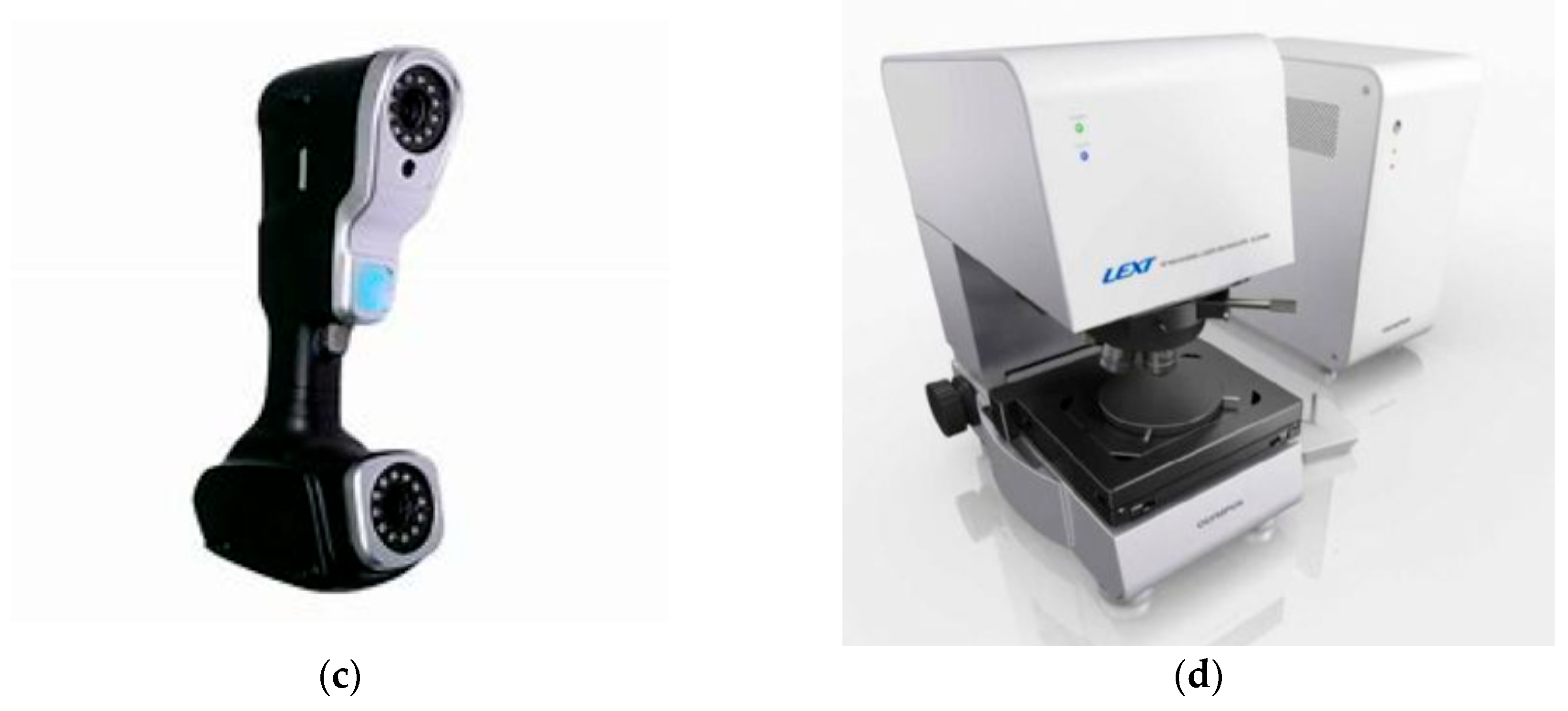
In 1936, E J. Abbott worked on the first exterior roughness profiler for shop use, and in 1940 Taylor-Hobsong developed a successful stylus-type exterior profile measurement. Subsequently, Whitehouse [100] revised and improved the method of measuring surface profile; today’s mechanical probe-type profilometer is shown in Figure 15a. Its use of mechanical probe-type profilometer can measure a large range of surface topography, but can easily damage the surface being measured, and at the same time, it is less efficient. Fan [101] used a Leica white light confocal interference microscope to sample the bonded rough surface, as shown in Figure 15b. Multiple cross sections were randomly selected from the specimen surface contour along a certain direction, and the 2D contour map was obtained after extracting the contour data points on the cross sections. Liu et al. [102] used a binocular laser scanner, as shown in Figure 15c. The 3D point cloud data is obtained by scanning the surface and later visualizing the point cloud data in grid form. Cao and Jing [103] used LEXT OLS4000 laser confocal microscope to test and capture the surface morphology and surface roughness of the mechanical bonding surface with the instrumentation, as shown in Figure 15d. The contour morphology of the rough surface was obtained, and then a contact stiffness model characterized from a microscopic point of view was established based on the upper and lower limit parameters of the asperity scale.
Figure 14.
3D rough surface topography [101].
Figure 14.
3D rough surface topography [101].

When establishing the statistical summation theoretical model, the degree of dispersion between the statistical parameters is too high, and the error of the contour parameters will inevitably cause large fluctuations in the fitting curve, which leads to a decrease in the accuracy of the bonded surface modeling; as such, it is necessary to determine the reasonableness of the assumption of the asperity, the accuracy of the distribution function of the rough surface, and to coordinate the diversity of the intrinsic model. The measurement of the rough surface morphology is an important means of verifying the accuracy of the theoretical model.
2.3.2. Parameter Identification of Contact Fractals
Unlike the classical statistics surface characterization parameters of height rms, slope, and curvature, the fractal characterization parameters G and D are independent of . The fractal dimension D reflects the complexity and irregularity of the rough surface profile and represents the similarity parameter. The scale parameter G is an absolute measurement parameter, reflecting the flatness of the rough surface in unit scale. At the same time, these two parameters cannot represent the topographic characteristics of the rough surface alone; only through the variation of their matching each other can determine the rough surface of different topographic characteristics. Fractal features are characterized by identifying and describing the order behind the actual disorder of the roughness of a rough surface. Therefore, if the fractal dimension D and the scale parameter G are known, the roughness amplitude at any length scale within the fractal region can be obtained. This is particularly important for studying the effect of surface roughness on any physical phenomenon at the relevant length scale.
Connolly et al. [104,105] experimentally investigated the effect of material hardness on the morphological characteristics of the joint interface and the joint stiffness. Different surface conditions, machining methods, and surface dimensions were considered in their study to provide quantitative data for typical mechanical bonding surfaces.
Yoshimura [106] applied the equivalent spring stiffness and damping coefficients to the bolted joints interface and guideway bond surface, and then modeled and identified them. By combining experiments and numerical simulations, based on the simplified contact model of the connection interface, the intrinsic frequency of the structure was obtained and compared with the modal experimental data to verify the reasonableness and accuracy of the method. Syed-Asif et al. [107] measured the contact stiffness and damping of the specimen by using a composite nanoindentation instrument through the quantitative imaging technique and the method of image recognition, and the composite nanoindentation instrument was shown in Figure 16.
Arora [109,110] and Pradhan et al. [111] identified the mass matrix, stiffness matrix, and damping matrix of the structure and analyzed them in comparison with the experimental values with a high accuracy; the integrated frequency response function matrix of the structure was obtained experimentally. LEE and KIM [112] derived the damping matrix for the equations of motion of the system from the frequency response function matrix of the system. The accuracy of the identification of the damping matrix depends on the accuracy of the frequency response function measurement. The damping matrix established by this method contains more information than the damping ratio and the actual spatial distribution of damping in the system can be obtained.
Mao et al. [113] studied the dynamic modeling of the fixed bonding surface of machine tools and the method of model parameter identification, based on which the degree of influence of the bolt preload on the dynamic modeling parameters of the fixed bonding surface was investigated.
Li et al. [114,115] obtained the frequency response function matrix of the bolted joints structure through experimental modal analysis and used the iterative method to obtain the sensitivity of the structure in the whole frequency band, determine the identification range, and improve the identification accuracy.
Wang et al. [116] measured the roughness of rough surfaces by using a handheld roughness measuring instrument, modeled the rough surfaces by using fractal theory, and investigated the analytical theoretical model for introducing roughness parameters.
2.4. Overview of Theoretical Modelling of Bolted Joints Interfaces from Microscopic Surface Contact Mechanisms
Bolted joints structure is an important part of mechanical equipment. Its stiffness characteristics and damping characteristics have a large impact on the overall mechanical properties of the equipment. The working phase of the bolted interface will produce non-linear behavior such as contact, separation, slip, adhesion, etc., in the normal and tangential directions. The nonlinear behavior of the bolted interface can lead to failure behaviors such as preload relaxation and nonlinear degradation of the connection stiffness. The stiffness degradation of the connection interface poses a great challenge to the prediction of equipment dynamic performance, reliability assessment, and structural design. Therefore, it is of great significance to establish a theoretical model of bolted joints interface from the interface contact mechanism. Many scholars have conducted a lot of work to reveal the contact slip mechanism of rough surfaces.
Mantelli et al. [117] developed a statistical model for pressure distribution in bolted connections. The use of the Weibull probability density distribution was proposed to predict the shape of the contact pressure distribution in bolted metal connections. The correlation based on the Weibull distribution agrees very well with the data. The results show that the Weibull function is an appropriate model for the shape of the contact pressure distribution in bolted connections.
Belhadjamor et al. [118] used numerically generated non-Gaussian surfaces to develop an FE model to investigate the contact properties and normal stiffness of the bond surface. The article investigated the effect of the degree and peak of asymmetry on the rough contact properties. The contact between two rough surfaces was modelled as a contact between a rigid plane and an elasto-plastic rough surface, considering work-hardening and the interaction between the rough surfaces. The Pearson Frequency Curve system was used to generate the non-Gaussian random surfaces.
Yang et al. [119] proposed a finite element analysis method on the contact of microscopic two rough surfaces. The method can study the complex contact mechanical behaviors of rough surfaces. Gaussian or non-Gaussian rough surfaces with different statistical characteristics were obtained by a digital characterization method of 3D rough surfaces. A fine finite element analysis model of the contact between two rough surfaces was constructed by bottom-up 3D modelling with hexahedral meshing. The contact characteristics such as deformation, contact pressure, true contact area, and loading/unloading characteristics of the microscopic bonding surfaces were analyzed under different normal loads. The study reveals the mechanical behavior of the bonding surface. It also provides an effective way to predict the performance of microscopic rough surfaces.
Buczkowski and Kleiber [120] developed a complete elastoplastic microcontact model for anisotropic rough surfaces. The rough surface is modelled as a stochastic process where the surface height is considered as a two-dimensional random variable. The surface is assumed to be statistically homogeneous. The description of anisotropic random surfaces focuses on strongly rough surfaces; for such surfaces, the vertices are represented by highly eccentric elliptic paraboloidal surfaces. The model is based on the conservation of volume on convex surfaces, with modifications to the plasticity index to accommodate a wider range of geometrical contact shapes during plastic deformation. Using the model, it is possible to determine the total contact area, contact load, and contact stiffness, which are combinations of elastic, elastoplastic, and plastic components.
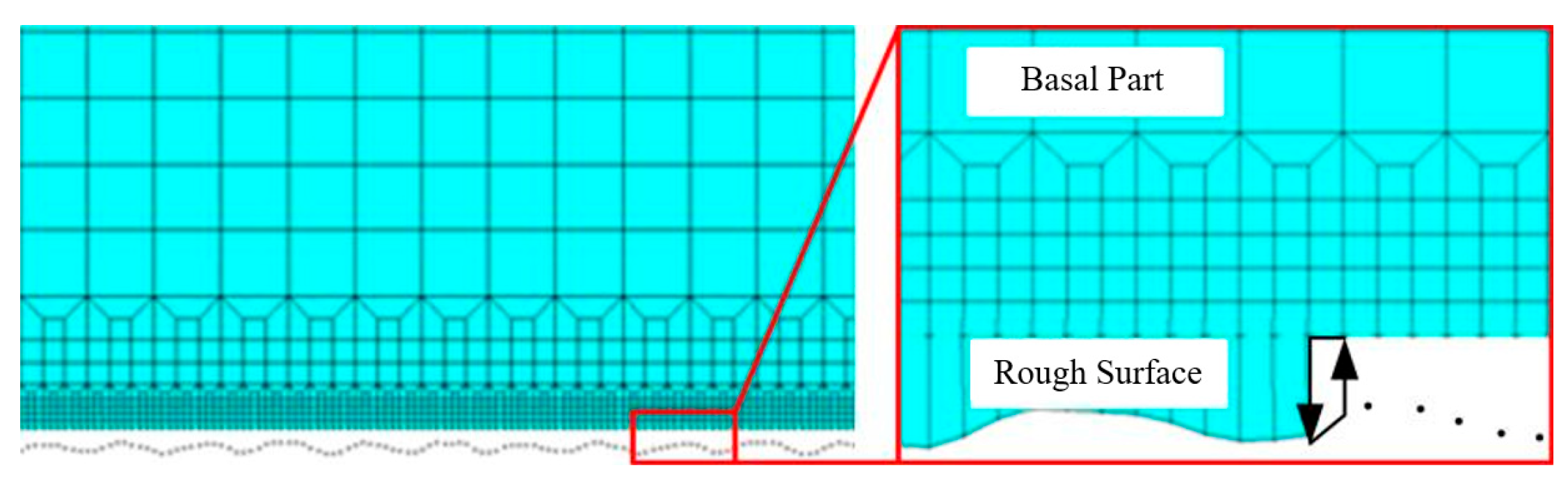
Zhu et al. [121] proposed a contact performance model for bolted joints considering macro-micro geometries. The model can accurately predict the real contact state of bolted joints. The problem of extracting and reconstructing the rough surface of the measured bolt joint bonding surface is solved by wavelet decomposition method, as shown in Figure 17. A cross-scale model of bolted joints considering the coupling of microscopic morphology and macroscopic geometry is constructed, as shown in Figure 18.
The pressure distribution of the bonding surface of the connected parts was measured by a pressure thin-film sensor. The effects of the thickness of the connected parts, the bolt preload, and the bolt size on the contact performance of the bond surface were analyzed. It provides support for the reliable assessment of the assembly performance of mechanical equipment such as stiffness, damping, and sealing.
3. Discussion
This review focuses on theoretical models of contact mechanics for rough surfaces. Based on the rough surface contact model, the cross-scale model of bolted joints structure is introduced. Bolted joints structures are very important fasteners in mechanical equipment. The image-only models of bolted joints structures have been developed and applied very maturely. However, there is still significant room for the development of the intrinsic model from the microscopic contact mechanism.
The asperity is the basic building block of rough surfaces. There are still many assumptions in the theoretical modelling of asperities. For example, it is assumed that the volume is constant. But when relative slip occurs between two rough surfaces, there must be wear and volume loss on the surface. Rough surfaces are in turn composed of many asperities. Both the statistical summation model and the contact fractal model are currently only studied in two dimensions. The extension of the theoretical modelling process to three-dimensional surfaces is also one of the trends in rough surface modelling.
First, the surface topography is modelled. The surface topography is then imposed on the numerical model or finite element model that builds the bolted joints structure. In this way, the mechanical properties, such as stiffness degradation of the structure, can be predicted more accurately. The modelling of surface morphology requires fine measurements by experimental instruments. The development of experimental instrumentation is also part of the constraints on this research direction. Through the mutual verification of experimental and theoretical models, better theoretical support can be provided for the prediction and evaluation of equipment performance guarantee.
4. Conclusions
There are many complex and large devices in use across industries such as aerospace, weaponry, and transport. However, the bolted joints structure on complex equipment is an important connection method for the whole equipment. It has the characteristics of nonlinear damping and nonlinear stiffness. Therefore, it is particularly important to accurately describe the contact characteristics of bolted joints structures at the connection interface. To analyze the contact characteristics of the connection interface from the fundamental mechanism, the “bottom-up” cross-scale analysis method is particularly important.
A theoretical model of the bolted joints interface is established from the microscopic contact mechanism. This can provide a better understanding and prediction of the mechanical behavior of the bolt such as stiffness degradation and damping characteristics. The basis of the microscopic contact mechanism is the asperity interaction and rough surface interaction. The basic problem of contact mechanics is the elastic-plastic contact of spherical or aspherical asperities on a rough surface under tangential or normal loading. To better explain the contact mechanism of two rough interfaces at the microscopic scale, it is crucial to establish a suitable theoretical model of the asperity. Therefore, this paper summarizes the theoretical model for the whole process of asperity deformation. As for the interaction between rough surfaces, it is necessary to model the surfaces by means of statistical summation or contact fractal. Therefore, this paper summarizes the current development of statistical summation and contact fractal models, respectively.
A more accurate contact surface model can be established by surface topography measurement. Combined with the finite element model of the bolted joints structure, the bolted joints structure can be better simulated and analyzed. Stress-strain measurements cannot be carried out during the use of bolted interfaces, and the bolts must be disassembled to be measured. The finite element model of the bolted joints structure with surface morphology parameters can obtain the above data through simulation so as to accurately predict the mechanical properties of the bolted joints structure.
There are still issues to be resolved in the future:
- (1)
- Dynamic normal loads in the case of preload relaxation are introduced to the bolted joints structure. Establish a more realistic theoretical model of the asperity. Consider the following factors: (1) elastic-plastic deformation process of the asperity; (2) frictional wear; (3) ellipsoidal asperity eccentricity; (4) ellipsoidal asperity interactions; (5) substrate deformation; (6) material hardness; (7) material intrinsic model; (8) dynamic change of the loads and non-uniform distribution; (9) tangential load-normal load coupling; (10) scale effect of the material’s mechanical behavior; and (11) horizontal distance of the asperity on the surface. A clearer theoretical analysis of the connection interface contact mechanism.
- (2)
- Precision surface topography measurement instruments are used to obtain the topographic distribution of rough surfaces in three dimensions. The precision surface topography measurement instrument is used to obtain the accurate topography parameters of the connection interface. The three-dimensional distribution function of the asperity is fitted to establish a more accurate contact mechanics model of the connection interface.
- (3)
- Based on the various performance parameters of the asperity, the parameters are coupled. Establish the mechanical model of the connection interface under the coupling condition so as to obtain a more accurate connection stiffness degradation model. From the microscopic contact mechanism, it provides theoretical support for predicting the stiffness degradation of bolted joints structures and the reliability assessment of large and complex equipment.
- (4)
- Establish a three-dimensional finite element model of the bolted joints structure. Add the 3D surface topography of the rough surface to the finite element model. Simulate and analyze from the perspective of microscopic contact mechanism so as to obtain more accurate bolt degradation characteristics.
Author Contributions
Y.L. and M.Z. summarized the current state of development and frontiers of the various efforts. X.L. and S.W. organized and classified the relevant literature. Z.L. reviewed and edited the manuscript. All authors have read and agreed to the published version of the manuscript.
Funding
This research received no external funding.
Institutional Review Board Statement
Not applicable.
Informed Consent Statement
Not applicable.
Data Availability Statement
Data sharing does not apply to this article.
Conflicts of Interest
The authors declare no conflict of interest.
References
- Cao, J.Y. A review on the study of micro-friction to macro-dynamics of bolted joints. China Mech. Eng. 2021, 32, 1261–1273. [Google Scholar]
- Wu, X.Y.; Zhu, S.J. Rational modeling of bolted coupling structure in FE modal calculation. J. Nav. Eng. Univ. 1998, 1, 67–71. [Google Scholar]
- Wen, S.C.; Huang, P. Principles of Tribology, 3rd ed.; Tsinghua University Press: Beijing, China, 2008. [Google Scholar]
- Jin, J.; Wu, X.Y.; Zheng, J.H. Study on the improvement of prestressing application method for bolted joints. J. Nav. Eng. Univ. 2010, 22, 20–24. [Google Scholar]
- Gaul, L.; Nitsche, R. The role of friction in mechanical joints. Appl. Mech. Rev. 2001, 54, 93–106. [Google Scholar] [CrossRef]
- Iwan, W.D. A Distributed-element Model for Hysteresis and Its Steady-state Dynamic Response. J. Appl. Mech. 1966, 33, 893–990. [Google Scholar] [CrossRef]
- Li, Y.K.; Hao, Z.M. A six-parameter Iwan model and its application. Mech. Syst. Signal Process. 2015, 68–69, 354–365. [Google Scholar] [CrossRef]
- Wang, D.; Xu, C.; Wan, Q. Modeling Tangential Contact of Rough Surfaces With Elastic- and Plastic-Deformed Asperities. ASME J. Tribol. 2017, 139, 051401. [Google Scholar] [CrossRef]
- Hertz, H. On the contact of elastic solids. J. Reine Angew. Math. 1881, 92, 156–171. [Google Scholar]
- Jung, C.C. Elastic-plastic contact analysis of an ellipsoid and a rigid flat. Tribol. Int. 2010, 43, 491–502. [Google Scholar]
- Kogut, L.; Etsion, I. A Semi-Analytical Solution for the Sliding Inception of a Spherical Contact. ASME J. Tribol. 2003, 125, 499–506. [Google Scholar] [CrossRef]
- Halling, J.; Nuri, K.A. Elastic-plastic contact of surfaces considering ellipsoidal asperities of work-hardening multi-phase materials. Tribol. Int. 1991, 24, 311–319. [Google Scholar] [CrossRef]
- Yuan, W.K.; Long, J.M.; Wang, G.F. Micro/Nano contact between a rigid ellipsoid and an elastic substrate with surface tension. ASME J. Appl. Mech. 2017, 84, 011012. [Google Scholar] [CrossRef]
- Greenwood, J.; Williamson, J. Contact of nominally flat surfaces. Proc. R. Soc. Lond. Ser. A Math. Phys. Sci. 1966, 295, 300–319. [Google Scholar]
- Greenwood, J.; Tripp, J. The contact of two nominally flat rough surfaces. Proc. Inst. Mech. Eng. 1970, 185, 625–633. [Google Scholar] [CrossRef]
- Ciavarella, M.; Greenwood, J.; Paggi, M. Inclusion of “interaction” in the Greenwood and Williamson contact theory. Wear 2008, 265, 729–734. [Google Scholar] [CrossRef]
- Whitehouse, D.J.; Archard, J.F. The properties of random surfaces of significance in their contact. Proc. R. Soc. Lond. 1970, 316, 97–121. [Google Scholar]
- Hill, R. The Mathematical Theory of Plasticity; Oxford University Press: Oxford, UK, 1998. [Google Scholar]
- Abbott, E.J.; Firestone, F.A. Specifying surface quality: A method based on accurate measurement and comparison. ASME J. Mech. Eng. 1933, 55, 569–572. [Google Scholar]
- Ishlinskii, A.Y. Axisymmetric problem of plasticity and the brinnel test. Appl. Math. Mech. 1944, 8, 201–224. [Google Scholar]
- Tabor, D. The hardness of solids. Rev. Phys. Technol. 1970, 1, 145. [Google Scholar] [CrossRef]
- Matthews, J.R. Indentation hardness and hot pressing. Acta Metall. 1980, 28, 311–318. [Google Scholar] [CrossRef]
- Chang, W.R.; Etsion, I.; Bogy, D.B. An elastic-plastic model for the contact of rough surfaces. J. Tribol.-Trans. ASME 1987, 109, 257–263. [Google Scholar] [CrossRef]
- Chang, W.R.; Etsion, I.; Bogy, D.B. Static friction coefficient model for metallic rough surfaces. J. Tribol.-Trans. ASME 1988, 110, 57–63. [Google Scholar] [CrossRef]
- Chang, W.R.; Etsion, I.; Bogy, D.B. Adhesion model for metallic rough surfaces. J. Tribol.-Trans. ASME 1988, 110, 50–56. [Google Scholar] [CrossRef]
- Zhao, Y.; Maietta, D.M.; Chang, L. An asperity micro contact model incorporating the transition from elastic deformation to fully plastic flow. J. Tribol. 2000, 122, 86–93. [Google Scholar] [CrossRef]
- Kogut, L.; Etsion, I. Elastic-plastic contact analysis of a sphere and a rigid flat. J. Appl. Mech.-Trans. ASME 2002, 69, 657–662. [Google Scholar] [CrossRef]
- Jackson, R.L.; Green, I. A finite element study of elasto-plastic hemispherical contact against a rigid flat. J. Tribol.-Trans. ASME 2005, 127, 343–354. [Google Scholar] [CrossRef]
- Brake, M.R.; Reu, P.L.; Vangoethem, D.J. Experimental validation of an elastic-plastic contact model. In Proceedings of the ASME International Mechanical Engineering Congress & Exposition, Denver, CO, USA, 11–17 November 2011; IMECE2011-65736. Volume 7, pp. 733–744. [Google Scholar]
- Brake, M.R. An analytical elastic-perfectly plastic contact model. Int. J. Solids Struct. 2012, 49, 3129–3141. [Google Scholar] [CrossRef]
- Zhao, Y.W.; Lv, Y.M.; Jiang, J.Z. A new elastic-plastic contact model for rough surfaces. J. Mech. Eng. 2007, 43, 95–101. [Google Scholar] [CrossRef]
- Xu, C.; Wang, D. An improved analytical model for normal elastic-plastic contact on rough surfaces. J. Xi’an Jiaotong Univ. 2014, 48, 115–121. [Google Scholar]
- Chen, Y.H.; Zhang, X.L.; Wen, S.H.; Lan, G.S. Normal Contact Damping Modeling on Joint Surfaces Considering Expansion Factor of Distribution Domain. J. Xi’an Jiaotong Univ. 2019, 53, 126–135. [Google Scholar]
- Wang, D.; Zhang, Z.S.; Jin, F. Normal contact model for elastic and plastic mechanics of rough surfaces. Acta Mech. Solida Sin. 2019, 32, 148–159. [Google Scholar] [CrossRef]
- Zhang, H.; Goltsberg, R.; Etsion, I. Modeling Adhesive Wear in Asperity and Rough Surface Contacts: A Review. Materials 2022, 15, 6855. [Google Scholar] [CrossRef]
- Li, B.; Li, P.; Zhou, R.; Feng, X.Q.; Zhou, K. Contact mechanics in tribological and contact damage-related problems: A review. Tribol. Int. 2022, 171, 107534. [Google Scholar] [CrossRef]
- Bhushan, B. Contact mechanics of rough surfaces in tribology: Multiple asperity contact. Tribol. Lett. 1998, 4, 1–35. [Google Scholar] [CrossRef]
- Salari, S.; Beheshti, A. Asperity-based contact and static friction with provision for creep: A review. Surf. Interfaces 2021, 24, 101144. [Google Scholar] [CrossRef]
- Flores, P. Contact mechanics for dynamical systems: A comprehensive review. Multibody Syst. Dyn. 2022, 54, 127–177. [Google Scholar] [CrossRef]
- Tichy, J.A.; Meyer, D.M. Review of solid mechanics in tribology. Int. J. Solids Struct. 2000, 37, 391–400. [Google Scholar] [CrossRef]
- Ghaednia, H.; Wang, X.; Saha, S.; Xu, Y.; Sharma, A.; Jackson, R.L. A Review of Elastic–Plastic Contact Mechanics. Appl. Mech. Rev. 2017, 69, 060804. [Google Scholar] [CrossRef]
- Onions, R.A.; Archard, J.F. The contact of surfaces having a random structure. J. Phys. D 2002, 6, 289–304. [Google Scholar] [CrossRef]
- Tang, Z.C.; Jiao, Y.Y.; Wong, L.N.Y. Theoretical model with multi-asperity interaction for the closure behavior of rock joint. Int. J. Rock Mech. Min. Sci. 2017, 97, 15–23. [Google Scholar] [CrossRef]
- Phan-thien, N. On an elastic theory of friction. ASME J. Appl. Mech. 1981, 48, 438–439. [Google Scholar] [CrossRef]
- Mindlin, R.D. Compliance of elastic bodies in contact. ASME J. Appl. Mech. 1949, 16, 259–268. [Google Scholar] [CrossRef]
- Courtney-Pratt, J.S.; Eisner, E. The effect of a tangential force on the contact of metallic bodies. Proc. R. Soc. 1957, 238, 529–550. [Google Scholar]
- Tas, N.R.; Gui, C.; Elwenspoek, M. Static friction in elastic adhesion contacts in MEMS. J. Adhes. Sci. Technol. 2003, 17, 547–561. [Google Scholar] [CrossRef]
- Jones, R.E. A Greenwood-Williamson model of small-scale friction. J. Appl. Mech. 2007, 74, 31–40. [Google Scholar] [CrossRef]
- Farhang, K.; Segalman, D.; Starr, M. Approximate constitutive relation for lap joints using a tribo-mechanical approach. In Proceedings of the International Modal Design Engineering Technical Conference & Computers and Information in Engineering Conference, Las Vegas, NV, USA, 4–7 September 2007; pp. 1–8. [Google Scholar]
- You, J.M.; Chen, T.N. Statistical modeling of static contact parameters of bonding surfaces. Vib. Shock 2010, 29, 47–50. [Google Scholar]
- You, J.M.; Chen, T.N. Statistical modeling of static friction coefficient of bonding surfaces. Vib. Shock 2010, 29, 26–29. [Google Scholar]
- Kragelsky, I.V.; Demkin, N.B. Contact area of rough surfaces. Wear 1960, 3, 170–187. [Google Scholar] [CrossRef]
- Argator, I.I.; Butecher, E.A. On the Iwan models for lap-type bolted joints. Int. J. Non-Linear Mech. 2011, 46, 347–356. [Google Scholar] [CrossRef]
- Wang, D.; Xu, C. A tangential stick-slip friction model considering rough binding surfaces. J. Mech. Eng. 2014, 50, 129–134. [Google Scholar] [CrossRef]
- Wang, D. Nonlinear Mechanical Modeling of Connected Interfaces in Structural Dynamics Problems. Master’s Thesis, Northwestern Polytechnical University, Xi’an, China, 2017. [Google Scholar]
- Megalingam, A.; Mayuram, M.M. A comprehensive elastic-plastic single-asperity contact model. Tribol. Trans. 2014, 57, 324–335. [Google Scholar] [CrossRef]
- Shankar, S.; Mayuram, M.M. A finite element based study on the elastic-plastic transition behavior in a hemisphere in contact with a rigid flat. J. Tribol. 2008, 130, 044502. [Google Scholar] [CrossRef]
- Xu, Y.; Jackson, R.L.; Marghitu, D.B. Statistical model of nearly complete elastic rough surface contact. Int. J. Solids Struct. 2014, 51, 1075–1088. [Google Scholar] [CrossRef]
- Nayak, P.R. Random process model of rough surfaces. ASME J. Lubr. Tech. 1971, 93, 398–407. [Google Scholar] [CrossRef]
- Nayak, P.R. Random process model of rough surfaces in plastic contact. Wear 1973, 26, 305–333. [Google Scholar] [CrossRef]
- Bush, A.W.; Gibson, R.D.; Thomas, T.R. The elastic contact of a rough surface. Wear 1975, 19, 163–168. [Google Scholar] [CrossRef]
- Bush, A.W.; Gibson, R.D.; Keogh, G.P. The limit of elastic deformation in the contact of rough surfaces. Mech. Res. Commun. 1976, 3, 169–174. [Google Scholar] [CrossRef]
- Greenwood, J.A. A simplified elliptic model of rough surface contact. Wear 2006, 261, 191–200. [Google Scholar] [CrossRef]
- Song, H.; Vakis, A.I.; Liu, X. Statistical model of rough surface contact accounting for size-dependent plasticity and asperity interaction. J. Mech. Phys. Solids 2017, 106, 1–14. [Google Scholar] [CrossRef]
- Majumdar, A.; Bhushan, B. Role of fractal geometry in roughness characterization and contact mechanics of surfaces. J. Tribol. 1990, 112, 205–216. [Google Scholar] [CrossRef]
- Majumdar, A.; Bhushan, B. Fractal model of elastic-plastic contact between rough surfaces. J. Tribol. 1991, 113, 1–11. [Google Scholar] [CrossRef]
- Yan, W.; Komvoulos, K. Contact analysis of elastic-plastic fractal surfaces. J. Appl. Phys. 1998, 84, 3617–3623. [Google Scholar] [CrossRef]
- Zhang, L.X.; Zhao, Y.P. Adhesion of rough surfaces with plastic deformation. J. Adhes. Sci. Technol. 2004, 18, 715–729. [Google Scholar] [CrossRef]
- Morag, Y.; Etsion, I. Resolving the contradiction of asperities plastic to elastic mode transition in current contact models of fractal rough surfaces. Wear 2007, 262, 624–629. [Google Scholar] [CrossRef]
- Miao, X.; Huang, X. A complete contact model of a fractal rough surface. Wear 2014, 309, 146–151. [Google Scholar] [CrossRef]
- Yuan, Y.; Cheng, Y.; Liu, K. A revised Majumdar and Bushan model of elastoplastic contact between rough surfaces. Appl. Surf. Sci. 2017, 425, 1138–1157. [Google Scholar] [CrossRef]
- Cao, H.; Zhu, M.; Li, B.; Lu, X.; Li, H.; Guo, M.; Wu, F.; Xu, Z. Theoretical Study of the Friction Coefficient in the M-B Model. Coatings 2022, 12, 1386. [Google Scholar] [CrossRef]
- Zhang, X.; Chen, Y.; Wen, S. Modeling of normal contact stiffness of bond surface considering elastic-plastic deformation mechanism. J. Vib. Eng. 2015, 28, 91–99. [Google Scholar]
- Wen, S.; Zhang, X.; Wu, M. Fractal modeling and simulation of normal contact stiffness of bonding surface. J. Agric. Mach. 2009, 40, 197–202. [Google Scholar]
- Wang, Y.H.; Zhang, X.L.; Wen, S.H.; Chen, Y.H.; Lan, G.S. Fractal Theoretical Model of Normal Contact Stiffness of Mechanical Joint Interfaces. J. Mech. Strength 2020, 42, 648–653. [Google Scholar]
- Liou, J.L.; Lin, J.F. A modified fractal microcontact model developed for asperity heights with variable morphology parameters. Wear 2010, 268, 133–144. [Google Scholar] [CrossRef]
- Liou, J.L.; Tsai, C.M.; Lin, J.F. A microcontact model developed for sphereand cylinder-based fractal bodies in contact with a rigid flat surface. Wear 2010, 268, 431–442. [Google Scholar] [CrossRef]
- Chen, H.; Dong, G.; Yin, Q.; Tan, F.; Yin, G.F. Normal contact stiffness modeling of bonding surfaces based on fractal theory. J. Vib. Shock 2019, 38, 218–224. [Google Scholar]
- Huang, Y.; Fu, W.; Tong, J. Parametric study on normal dynamic characteristics of bonding surface. J. Mech. Eng. 1993, 29, 74–78. [Google Scholar]
- Yang, H.; Fu, W.; Wang, W. Computational method of wavelet coefficients characterizing fractal features of machined surfaces. J. Instrum. 2010, 31, 1454–1459. [Google Scholar]
- Yang, H.; Fu, W.; Wang, W. Calculation model of normal contact stiffness of bonding surface based on fractal geometry and contact mechanics theory. J. Mech. Eng. 2013, 49, 102–107. [Google Scholar] [CrossRef]
- Wang, W.; Wu, J.; Fu, W. Theoretical modeling and experimental study of normal dynamic contact stiffness of mechanical bonding surfaces. J. Mech. Eng. 2016, 52, 123–130. [Google Scholar] [CrossRef]
- Fu, W.; Lou, L.; Gao, Z. Theoretical modeling of normal contact stiffness and damping of mechanical bonding surfaces. J. Mech. Eng. 2017, 53, 73–82. [Google Scholar] [CrossRef]
- Tian, X.; Wang, W.; Fu, W. Contact stiffness modeling of mechanical bonding surfaces considering asperity interactions. J. Mech. Eng. 2017, 53, 149–159. [Google Scholar] [CrossRef]
- Wang, W.; Wu, J.; Gao, Z.; Fu, W. Computational modeling of tangential contact damping of mechanical bonding surfaces. J. Mech. 2018, 50, 633–642. [Google Scholar]
- Gao, Z.Q.; Fu, W.P.; Wang, W. Normal damping model of mechanical joints interfaces considering asperities in lateral contact. J. Tribol. 2017, 140, 021404. [Google Scholar] [CrossRef]
- Gao, Z.Q.; Fu, W.P.; Wang, W. Normal contact damping model of mechanical interface considering asperity shoulder-to-shoulder contact and interaction. Acta Mech. 2019, 230, 2413–2424. [Google Scholar] [CrossRef]
- Cheng, Y.; Yuan, Y.; Gan, L. Scale-dependent elastic-plastic contact mechanics modeling of fractal rough surfaces. J. Northwest. Polytech. Univ. 2016, 34, 485–492. [Google Scholar]
- Cheng, Y.; Yuan, Y. Contact mechanics modeling of rough surfaces based on fractal theory. China Sci. Technol. Pap. 2016, 11, 1850–1854. [Google Scholar]
- Yuan, Y.; Zhang, J.; Cheng, Y. Elasto-plastic fractal contact modeling of cylindrical rough surfaces. Sci. China Technol. Sci. 2017, 47, 502–513. [Google Scholar]
- Chen, J.; Yuan, Y.; Xu, Y. Analytical modeling of loaded and unloaded fractal contact on rough surfaces. J. Xi’an Jiaotong Univ. 2018, 52, 98–110. [Google Scholar]
- Chen, J.; Yuan, Y.; Cheng, Y.; He, Y. Scale-dependent normal contact stiffness model for fractal bond surfaces. J. Mech. Eng. 2018, 54, 127–137. [Google Scholar] [CrossRef]
- Yuan, Y.; Yu, C.; Jing, Z. Three-dimensional rough surface elastic-plastic contact mechanics model based on fractals and experimental validation. Eng. Mech. 2018, 35, 209–221. [Google Scholar]
- Yuan, Y.; Zhang, L.; Xu, Y.Q. Mechanical Model of Contact Between a Sphere-Based Fractal Rough Surface and a Rigid Flat Surface. J. Xi’an Jiaotong Univ. 2019, 53, 176–186. [Google Scholar]
- Zhang, X.L.; Huang, Y.M.; Fu, W.P. Fractal modeling of normal contact stiffness on rough surfaces. J. Appl. Mech. 2000, 17, 31–36. [Google Scholar]
- Zhang, X.; Huang, Y.; Wen, S. Research on fractal modeling of contact stiffness of bonding surface. J. Agric. Mach. 2000, 31, 89–92. [Google Scholar]
- Zhang, X.L.; Huang, Y.M.; Han, Y. Normal contact stiffness model of mechanical bonding surface based on contact fractal theory. China Mech. Eng. 2000, 11, 727–729. [Google Scholar]
- Zhang, X.L.; Wen, S.H. Fractal model of tangential contact stiffness of bonding surface based on contact fractal theory. J. Agric. Mach. 2002, 33, 91–93. [Google Scholar]
- Zhang, X.L.; Wen, S.H.; Xu, G.L. Research on fractal modeling of tangential contact stiffness of bond. J. Appl. Mech. 2007, 43, 70–72. [Google Scholar]
- Whitehouse, D.J. Stylus Contact Method for Surface Metrology in the Ascendancy. Meas. Control 1988, 31, 48–50. [Google Scholar] [CrossRef]
- Fan, L.S.; Wang, S.J.; Wu, J.W. Modeling of Normal Contact Stiffness of Joint Considering the Horizontal Distance Distribution and Interaction between Asperities. J. Mech. Eng. 2022, 58, 201–214. [Google Scholar]
- Liu, G.; Ma, Q.; Cui, B. Research on contact law and shear stress modeling of two flank asperities during nodal shear. Geotechnics 2022, 43, 3357–3371+3384. [Google Scholar]
- Cao, H.; Jing, T. Characterization of normal contact stiffness of mechanical bonding surfaces based on generalized theory. J. Yan’an Univ. (Nat. Sci. Ed.) 2023, 42, 110–114. [Google Scholar]
- Connolly, R.; Thornley, R.H. Determining the normal stiffness of joint faces. J. Eng. Ind. 1968, 90, 97–106. [Google Scholar] [CrossRef]
- Connolly, R.; Schofield, R.E.; Thornley, R.H. The approach of machined surfaces with particular reference to their hardness. Adv. Mach. Tool Des. Res. 1968, 759–775. [Google Scholar] [CrossRef]
- Yoshimura, M. Computer-aided design improvement of machine tool structure incorporating joint dynamics data. Ann. CIRP 1979, 28, 241–246. [Google Scholar]
- Syed-Asif, S.A.; Wahl, K.J.; Colton, R.J. Quantitative imaging of nanoscale mechanical properties using hybrid nanoindentation and force modulation. J. Appl. Phys. 2001, 90, 1192–1200. [Google Scholar] [CrossRef]
- Fu, W.P.; Guo, Q.; Huang, Y.M. Experimental investigation of dynamic normal characteristics of machined joint surfaces. J. Vib. Acoust.-Trans. ASME 2000, 122, 393–398. [Google Scholar] [CrossRef]
- Arora, V.; Singh, S.P.; Kundra, T.K. Finite element model updating with damping identification. J. Sound Vib. 2009, 324, 1111–1123. [Google Scholar] [CrossRef]
- Arora, V. Structural damping identification method using normal FRFs. Int. J. Solids Struct. 2014, 51, 133–143. [Google Scholar] [CrossRef]
- Pradhan, S.; Modak, S.V. A method for damping matrix identification using frequency response data. Mech. Syst. Signal Process. 2012, 33, 69–82. [Google Scholar] [CrossRef]
- Mao, K.M.; Li, B.; Wu, J. Stiffness influential factors-based dynamic modeling and its parameter identification method of fixed joints in machine tools. Int. J. Mach. Tools Manuf. 2010, 50, 156–164. [Google Scholar] [CrossRef]
- Mao, K.; Huang, X.; Tian, H. Identification of machine tool fixed bonding surface parameters and its fitting method. J. Huazhong Univ. Sci. Technol. (Nat. Sci. Ed.) 2011, 39, 18–21. [Google Scholar]
- Li, L.; Cai, A.; Cai, L. Identification method of dynamic characteristics of bolted joint. J. Mech. Eng. 2013, 49, 168–175. [Google Scholar] [CrossRef]
- Li, L.; Cai, A.; Cai, L. A new method for identifying dynamic characteristic parameters of bolted joint. Vib. Shock 2014, 33, 15–19. [Google Scholar]
- Wang, J.; Peng, Y.; Zhao, X. Normal contact stiffness model between rolls considering friction. Iron Steel 2024, 59, 91–98. [Google Scholar]
- Mantelli, M.; Milanez, F.H.; Pereira, E.; Fletcher, L. Statistical Model for Pressure Distribution of Bolted Joints. J. Thermophys. Heat Transf. 2010, 24, 432–437. [Google Scholar] [CrossRef]
- Belhadjamor, M.; Belghith, S.; Mezlini, S.; EL Mansori, M. Numerical study of normal contact stiffness: Non-Gaussian roughness and elastic–plastic behavior. Proc. Inst. Mech. Eng. Part J J. Eng. Tribol. 2020, 234, 1368–1380. [Google Scholar] [CrossRef]
- Yang, G.; Xiong, M.; Hong, J.; Liu, H.; Wang, F. Numerical Characterization and Contact Performances for 3D Rough Surfaces. J. Xi’an Jiaotong Univ. 2012, 46, 58–63. [Google Scholar]
- Buczkowski, R.; Kleiber, M. Statistical models of rough surfaces for finite element 3D-contact analysis. Arch. Comput. Methods Eng. 2009, 16, 399–424. [Google Scholar] [CrossRef]
- Zhu, L.; Liang, H.; Zhang, H.; Shi, J.; Hong, J. Interface Contact Performance Model of Bolted Joints Considering Macro-Micro Morphology. J. Xi’an Jiaotong Univ. 2024, 11, 1–11. Available online: http://kns.cnki.net/kcms/detail/61.1069.T.20240109.1043.002.html (accessed on 20 March 2024).
Figure 1.
Schematic diagram of the bolt connection structure [1].
Figure 1.
Schematic diagram of the bolt connection structure [1].

Figure 2.
Microscopic contact model of mechanical friction at the connection interface. (a) When the two bonding surfaces are in contact. (b) When tangential micro-slip or macro-slip occurs on the two bonding surfaces [1].
Figure 2.
Microscopic contact model of mechanical friction at the connection interface. (a) When the two bonding surfaces are in contact. (b) When tangential micro-slip or macro-slip occurs on the two bonding surfaces [1].

Figure 3.
A common image-only model for connection structures. (a) Iwan model. (b) Lugre brush model. (c) Valanis model [5].
Figure 3.
A common image-only model for connection structures. (a) Iwan model. (b) Lugre brush model. (c) Valanis model [5].

Figure 5.
Overview of the focus section of the article.

Figure 6.
Schematic diagram of the smooth plane assumption [8].
Figure 6.
Schematic diagram of the smooth plane assumption [8].

Figure 7.
Schematic diagram of interaction assumptions. (a) Peak-to-peak contact. (b) Side contact.

Figure 8.
Schematic diagram of the contact between the rigid plane and the ellipsoid [10].
Figure 8.
Schematic diagram of the contact between the rigid plane and the ellipsoid [10].

Figure 9.
The classical asperity model.

Figure 10.
Three wear modes of surface asperities: (a) slipping; (b) plastic grinding; and (c) breakaway; (d) mixed modes [35].
Figure 10.
Three wear modes of surface asperities: (a) slipping; (b) plastic grinding; and (c) breakaway; (d) mixed modes [35].

Figure 11.
Forces on the contact surfaces in the fully elastic phase [8].
Figure 11.
Forces on the contact surfaces in the fully elastic phase [8].

Figure 12.
Qualitative description of the statistical self-affine profile of a rough surface profile [65].
Figure 12.
Qualitative description of the statistical self-affine profile of a rough surface profile [65].

Figure 13.
Schematic diagram of the contact between the asperity and the smooth rigid plane. (a) Isolated contacts from contact. (b) Geometry of contacting asperities [66].
Figure 13.
Schematic diagram of the contact between the asperity and the smooth rigid plane. (a) Isolated contacts from contact. (b) Geometry of contacting asperities [66].

Figure 15.
Diagram of precision instruments for measuring surface topography. (a) Mechanical probe profilers [100]. (b) Leica white light confocal interference microscope [101]. (c) Binocular laser scanner [102]. (d) LEXT OLS4000 laser confocal microscope [103].


Figure 16.
Composite nanoindentation device diagram [108].
Figure 16.
Composite nanoindentation device diagram [108].

Figure 17.
FE modeling of connected parts considering rough surfaces [121].
Figure 17.
FE modeling of connected parts considering rough surfaces [121].

Figure 18.
Macro-micro multi-scale analysis model of bolted joints [121].
Figure 18.
Macro-micro multi-scale analysis model of bolted joints [121].

Disclaimer/Publisher’s Note: The statements, opinions and data contained in all publications are solely those of the individual author(s) and contributor(s) and not of MDPI and/or the editor(s). MDPI and/or the editor(s) disclaim responsibility for any injury to people or property resulting from any ideas, methods, instructions or products referred to in the content. |
© 2024 by the authors. Licensee MDPI, Basel, Switzerland. This article is an open access article distributed under the terms and conditions of the Creative Commons Attribution (CC BY) license (https://creativecommons.org/licenses/by/4.0/).
Share and Cite
MDPI and ACS Style
Liu, Y.; Zhu, M.; Lu, X.; Wang, S.; Li, Z. A Review of Cross-Scale Theoretical Contact Models for Bolted Joints Interfaces. Coatings 2024, 14, 539. https://0-doi-org.brum.beds.ac.uk/10.3390/coatings14050539
AMA Style
Liu Y, Zhu M, Lu X, Wang S, Li Z. A Review of Cross-Scale Theoretical Contact Models for Bolted Joints Interfaces. Coatings. 2024; 14(5):539. https://0-doi-org.brum.beds.ac.uk/10.3390/coatings14050539
Chicago/Turabian StyleLiu, Yilong, Min Zhu, Xiaohan Lu, Shengao Wang, and Ziwei Li. 2024. "A Review of Cross-Scale Theoretical Contact Models for Bolted Joints Interfaces" Coatings 14, no. 5: 539. https://0-doi-org.brum.beds.ac.uk/10.3390/coatings14050539
Note that from the first issue of 2016, this journal uses article numbers instead of page numbers. See further details here.