1. Introduction
With the rapid advancement of urban construction, more and more foundation pit projects are located above or on both sides of existing subway tunnels. This leads to a significant impact on the complex underground pipeline network caused by the construction of nearby deep foundation pits [
1]. As a result, the impact of construction on adjacent existing subway tunnels has gradually become a concern.
The construction of foundation pits near existing operating subway tunnels can alter the displacement and stress fields of the surrounding soil [
2,
3]. The soil is affected by the stress changes caused by excavation and the displacement of surrounding soil, resulting in the corresponding local deformation of adjacent subway tunnels. At the same time, some rock, soil, and underground engineering structures, including deep foundation pit engineering and shield tunneling, can be considered as low toughness structures [
4]. Once additional unexpected events occur, the risk of large-scale damage or even a continuous collapse caused by local damage is relatively high. Therefore, solving the problem of existing tunnel deformation caused by excavation is of great significance for ensuring the safety and reliability of urban subway traffic operation.
In recent decades, numerous scholars have accumulated valuable insights into the deformation of existing tunnels resulting from pit excavation. Wu [
5] discovered through numerical analysis that the deformation of the nearby tunnel and ground settlement both reach their maximum values when the excavation of the pit reaches the bottom, with the overall deformation of the tunnel presenting a “horizontal oval” shape directed towards the excavation. Xie et al. [
6] have shown that the excavation of the pit has a greater impact on the lateral deformation and convergence of the tunnel, with the deformation increasing closer to the retaining structure at point H. Additionally, the technique of subway tunnel grouting for deviation correction was found to effectively control the development of deformation. Liu et al. [
7] found that the impact zone of deformation on nearby existing tunnels caused by pit excavation is related to geological conditions, pit conditions, and tunnel conditions, while the mechanism of impact on the tunnels lying beneath is much simpler than that on lateral tunnels. Fan et al. [
8] used three levels of deformation control standards for tunnel maximum deformation at 20 mm, 10 mm, and 5 mm, and found that the deformation impact zone on underlying tunnels could be divided into the main impact zone, secondary impact zone, general impact zone, and minor impact zone. Deng et al. [
9] discovered through measured data that the maximum uplift deformation of the subway structure caused by the excavation of pits on both sides occurs near the connection between the station and the tunnel; as the load intensity increases, the amount of uplift of the subway structure decreases, and when it exceeds a certain intensity, some sections of the interval tunnel will settle.
In the context of advancing urbanization, research on the excavation of foundation pit groups has emerged. Guo et al. [
10] used the finite element method to study the mutual influence of adjacent foundation pit simultaneous construction. The results showed that the simultaneous construction of two foundation pits caused significant horizontal deformation in the existing subway station, while the vertical settlement was relatively small. The overall impact of simultaneous construction on the deformation of existing nearby subway structures is roughly equal to the superposition of the effects of the excavation of the two foundation pits separately. Peng et al. [
11] analyzed the measured data of double foundation pit excavation and found that the excavation process of the foundation pit directly affects the deformation of the existing line foundation, and the impact of double foundation pit excavation on the deformation of the existing line foundation is superimposed. Huang [
12], through numerical simulation, clarified the positive impacts of isolation walls and in-pit reinforcement in controlling the deformation of foundation pits in split-pit excavation schemes. They concluded that the split-pit excavation scheme effectively mitigates the impact of the simultaneous construction of adjacent deep and large foundation pits. Zhang et al. [
13] employed numerical methods to investigate the influence of different arrangements of double foundation pit excavation on existing tunnels. They determined that in vertical arrangements, the impact of the far tunnel pit on tunnel displacement and deformation is minimal, while the overall horizontal displacement is influenced. Notably, the excavation of the near tunnel pit plays a decisive role in tunnel deformation. Ding et al. [
14] observed that after pit excavation, the excavated foundation pit tends to move as a whole, with the soil between the two foundation pits exhibiting a tendency to extrude toward the middle of the pit.
While previous studies have offered valuable insights into the impact of foundation pit excavation on existing lines, several issues warrant further exploration in the current discourse. Presently, numerous studies focus on conventional single pit excavation, with limited attention given to double pit or pit group excavation. Notably, there is a dearth of cases examining double pit excavation in the form of heterogeneous pits connected to circular end shafts. Moreover, existing research on double pit cases often involves pits distributed on both sides of the tunnel, with a tendency to concentrate on the mutual influence of these pits. Unfortunately, there is a notable gap in discussions regarding the excavation sequence of double pits on existing subway tunnels, resulting in an elusive understanding of the underlying patterns.
In this study, we draw upon the foundation pit project of the Beijing Urban Subcenter Comprehensive Transportation Hub. Specifically, we employ the Plaxis3D numerical simulation method to investigate the deformation response of adjacent existing subway tunnels in the circumferential direction, longitudinal direction, and tunnel interval. This exploration is conducted under three distinct excavation sequences for double pits: sequential, synchronous, and comprehensive excavation. The objective is to unveil the patterns governing the displacement changes within the tunnel under varying working conditions. The findings elucidate the systematic variations in tunnel displacement under these different scenarios.
2. Project Profile
The Beijing Urban Subcenter Comprehensive Transportation Hub is located in Lu Cheng Town, Tongzhou District, Beijing. It is the largest Transit-Oriented Development (TOD) project in Asia, integrating two intercity railways, one suburban railway, and four metro lines. The project implementation involves multiple adjacent or intersecting subway section projects, including tunneling beneath existing sections, proximity to foundation pits, elevated crossings over passageways, renovations to existing lines, and relocation and reconstruction efforts.
2.1. Overview of Excavation Site
This article focuses on the foundation pit project located in
Section 4 of the Urban Subcenter Transportation Hub Project, which is a critical railway core area encompassing the Jing-Tang end shaft, intercity end shaft, Jing-Tang core area, and intercity core area—comprising four foundation pits. Given that the intercity end shaft is closer to the existing subway lines than the Jing-Tang end shaft, it may potentially have a greater impact. Therefore, this study specifically addresses the intercity linked end shaft foundation pit and the intercity linked core area foundation pit, as illustrated by the spatial relationship in
Figure 1.
The overall shape of the intercity end shaft foundation pit is circular, with an inner diameter of 25.9 m and a depth of 40.21 m. The primary supporting structure includes an underground continuous wall, 10 concrete ring beams, and a concrete crown beam. The design service life is 2 years, and the safety level of the foundation pit is Level I. The excavation of the foundation pit is carried out using the open-cut method.
The overall shape of the intercity core area foundation pit is linear, with a length of 135 m, a width of 21.8–30 m, a depth of 28.4–35.4 m, and an area of 3492 square meters. The main supporting structure of the foundation pit includes an underground continuous wall, concrete internal support, and a concrete crown beam. The design service life of the foundation pit is 1 year, and the safety level is Level I. The excavation method for the range from the bottom of the pit to the top of the main structure is the open-cut method, while the excavation method from the top of the main structure to the bottom of the pit is the cover excavation method.
2.2. The Geological Condition of the Site
Based on the analysis of the geological survey results in the area of this section in the sub-center district, within the exploration depth of 107.00 m, the distribution characteristics of various soil layers are as follows: in the vertical direction, multiple sedimentary cycles of stable cohesive soil, silty soil, and sandy soil are observed; in the horizontal direction, there are certain variations in the thickness and soil characteristics of each layer. Specifically, it can be roughly divided into 17 layers, and the lithological combination characteristics at the exploration depth are detailed in
Table 1 and
Figure 2.
2.3. Position Relationship between Foundation Pit and Existing Subway
According to the standards stipulated in China’s “Urban Rail Transit Engineering Project Construction Standard” (JB 104-2008) [
15], which specify the minimum width requirements for the control protection boundaries of completed and planned routes, in the sections of completed routes, on the outer side of underground stations and tunnel structures, there should be a planned control protection boundary on each side with a width of 50 m.
Currently, the intercity joint end well and the core area foundation pit are both located north of the existing M6 line, with the nearest horizontal distance of 16.43 m from the joint end well foundation pit. The existing Metro Line M6 has a burial depth of 23.3 m in the project area, a tunneling section radius of 3 m, a segment thickness of 0.35 m, and a spacing of 15 m between the right and left tunnel lines. The specific relationship between the foundation pit and the profile position of the M6 line is detailed in
Figure 3. The construction of the intercity joint end well foundation pit and some of the core area foundation pits intrude into the control protection zone of the existing Metro Line 6, and construction is carried out in stages and segments. External operations have a complex impact on the internal forces and deformations of the structures in the existing metro line section.
3. Numerical Computation Model
Due to the complexity of the irregular excavation boundary in foundation pit construction, it is challenging to analyze the impact of pit excavation on subway tunnels through analytical methods [
16]. Therefore, this paper adopts a numerical simulation approach to study the effects of the excavation sequence of dual foundation pits on the deformation of subway tunnels.
3.1. Establishment of the Overall Foundation Pit Site
The calculation and analysis of the excavation and structural construction of the intercity junction well and the core area soil are simulated using Plaxis3D (CONNECT Edition V20) software. A finite element analysis model is established based on the actual site range, with a total length of 350 m, a total width of 350 m, and a total height of 120 m. According to the distribution characteristics of each soil layer within the depth range of geotechnical exploration in
Section 4 of the sub-center area, the soil distribution of the finite element model is divided. Refer to the next section for detailed soil parameters.
Based on the actual location of the site, a finite element model of the railway core area is established as shown in
Figure 4, including the Jing-Tang junction well, the intercity junction well, the Jing-Tang core area, and the intercity core area. The radius of the well at the junction is 14.15 m, and the maximum excavation depth is 40.25 m. The maximum excavation depth of the core area well is 36 m. The retaining wall structure is generally irregular and is established according to the actual site location, with a maximum depth of 80 m. The existing operating Metro Line M6 tunnel is simulated using panel units, with a panel thickness of 0.35 m and C40 concrete material. The closest horizontal distance from the tunnel to the Jing-Tang junction well excavation is 19.43 m, and the closest horizontal distance to the intercity junction well excavation is 16.43 m.
3.2. Site Establishment of Foundation Pit Support System
For the support system, the diaphragm wall is simulated using solid elements with a thickness of 1.2 m and a depth of 80.25 m. The concrete grade for the solid elements is C40. The structures such as reverse slabs and bottom slabs are simulated using built-in plate elements in Plaxis3D. The bottom slab thickness of the junction well is 3 m, the mid-slab B2 thickness in the core area is 3.5 m, and the general bottom slab thickness is 3 m. The concrete grade for the plate elements is C40. Temporary column piles are simulated using embedded pile elements with a pile radius of 400 mm, a pile length of 82 m, and a concrete grade of C35. The support structure for the junction well adopts the form of ring beams and crown beams, both simulated using beam elements. The crown beam dimensions are 1.5 m × 1.5 m, and the ring beam dimensions are 1.2 m × 1 m. The concrete grade for the beam elements is C35. The finite element model for the supporting structure is shown in
Figure 4.
3.3. Model Material Parameters
Although numerical simulation methods are widely used in the current research of foundation pits and tunnels, the selection of material model parameters, especially for nonlinear constitutive models and soil parameters, remains a challenge [
17].
The layered soil adopts the HSS small-strain model, which was introduced and modified by Benz [
18] based on the Hardin–Drnevich model [
19] to describe the hyperbolic relationship between shear stiffness and strain in the small-strain range of soil. This extends the HS model to a constitutive model that considers the nonlinear elastic relationship between shear stiffness and strain in the small-strain range of soil. The HSS model has 13 characterization parameters, including 11 HS model parameters and 2 small-strain parameters (
,
). The 11 HS model parameters can be further divided into 4 parameters (c′, φ′, ψ, Rf) related to strength and 7 parameters (p
ref, ν
ur, m, K0,
) related to stiffness. The specific meanings of each parameter and the experimental determination method are detailed in the references [
16,
18,
20]. In this paper, based on project geotechnical data, experiments, and the relevant literature, the HSS model is determined for the soil. The parameters of the artificial fill at the ground surface are determined based on geotechnical data and references [
20,
21,
22]. The parameters of other soil layers within the excavation range are determined from experimental data. The parameters of the soil layers below the bottom of the foundation pit are determined based on geotechnical data and references [
7]. Additionally, some parameters are inversely optimized and adjusted based on simulation results. Common parameters for all soil layers include
= 0.9,
= 100,
= 0.2, and m = 0.5. The detailed HSS model parameters for each soil layer are shown in
Table 2.
The constitutive models for the materials in the support system, including the diaphragm wall, lining, columns, supports, struts, bottom slab, ring beams, and crown beams, are all of the elastic type. The elastic modulus for the diaphragm wall, columns, supports, struts, and bottom slab is 31,500 MPa, while the elastic modulus for the tunnel lining is 34,500 MPa. The density of concrete is 25 kN/m3 for all materials in the support system, and the Poisson’s ratio for these materials is 0.2.
3.4. Convergence of Numerical Models
When analyzing and calculating numerical models, it is necessary to prioritize ensuring the convergence of the model. Therefore, in this numerical model, we use the K0 process for the initial stress equilibrium calculation, and use the Picos solver for subsequent plastic type multi-core iterative solutions. The maximum number of steps is 1000, with an allowable error of 0.01, and the maximum unloading step is set to 5, with a maximum iteration step of 60. Based on this, the numerical models described in the article converge normally after submitting jobs.
3.5. Verification of Numerical Calculation Models
Based on the established site model and its determined HSS soil constitutive model, we conducted validity tests on the numerical model established. The verification plan for this project is to only excavate the circular deep foundation pit to the bottom elevation, which is consistent with the actual construction and progress on site, and to compare and verify based on the monitoring data of the deep level on site. The specific monitoring points for deep horizontal displacement are shown in
Figure 5.
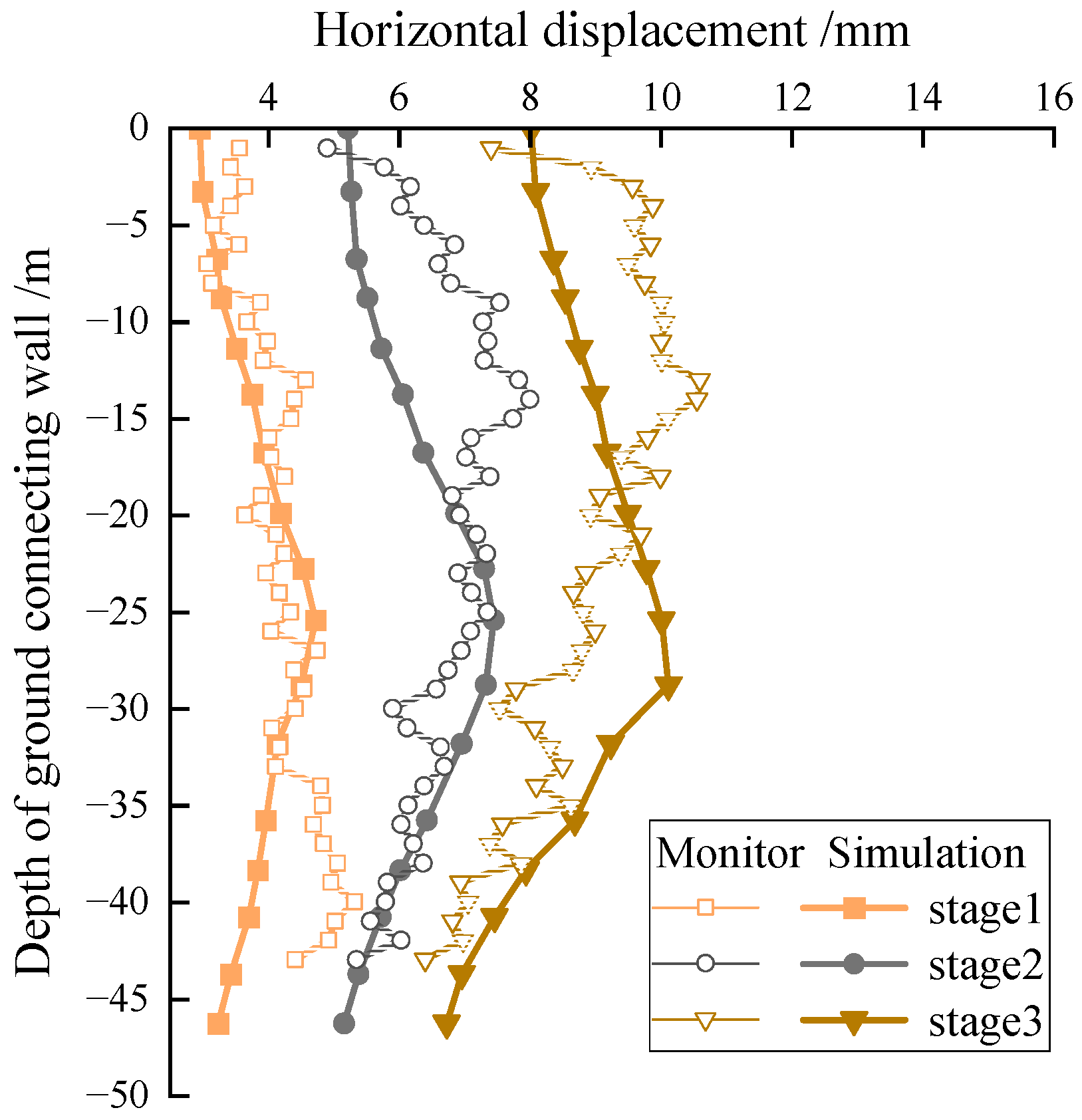
The horizontal displacement of the selected node varies with the depth of the connecting wall during excavation up to −18.75 m (stage 1), −27.75 m (stage 2), and −42.5 m (stage 9), as shown in
Figure 6. The horizontal displacement of the diaphragm wall at each measurement point increases to a maximum value with the increase in the burial depth of the diaphragm wall, and then gradually decreases. From the comparison of on-site measurement and the simulation calculation of horizontal displacement, it can be seen that the simulation results of this study can better describe the variation law of on-site measurement results, and the magnitude level of the obtained displacement is not significantly different. Overall, the finite element method of the HSS model used in this article can better reflect the effect of soil excavation on structural deformation, and is suitable for the simulation and analysis of ultra-deep foundation pit excavation in the site.
5. Results and Analysis
For the three excavation sequence plans mentioned above, numerical analysis is conducted using PLAXIS 3D software to assess their impact on the deformation of the existing railway line and their effectiveness.
5.1. The Selection of Tunnel Analysis Cross-Sections
The circumferential deformation of the tunnel is a crucial evaluation parameter as it helps to gain insights into the impact of soil excavation and unloading on the tunnel. In this study, we employed a selection criterion, choosing the tunnel cross-section where the total displacement at the nodes was the largest under the condition of simultaneous excavation (considered the most unfavorable scenario). The selected cross-section is illustrated in
Figure 10. This corresponds to the section at position N61174 in
Figure 8. On this circumferential section, we selected eight nodes at an average interval of every 45 degrees for detailed analysis.
5.2. The Results of the Impact on Vertical Displacement
The vertical displacement variations of four points, namely, the horizontal direction nodes N61174 (near end) and N59140 (far end) and the vertical direction nodes N5792 (upper end) and N7569 (lower end), in the circumferential cross-section under the three different excavation sequence plans are plotted in
Figure 11. Since the existing railway tunnel has been completed during the actual excavation (Plan 1), and the soil removal process (Plan 2) has been finished, these two conditions are set to have zero displacement in the numerical software. The numerical analysis only considers the phase starting from diaphragm wall construction (Plan 3), corresponding to the actual construction conditions.
Although the different steps of each construction phase represent different meanings in the graph, the results show a consistent trend in the upward vertical displacement of tunnel nodes and their relative magnitudes throughout the entire construction period across different excavation plans.
Sequential excavation (Plan 1) exhibits lower vertical displacement in the first half of the construction period. This is because the plan primarily focuses on excavating the circular junction well at the initial stage, resulting in a relatively small amount of soil removal and, consequently, a smaller degree of uplift in the nearby tunnel. However, in the second half of the construction period, as the volume of soil removal increases, the vertical displacement also increases.
Simultaneous excavation (Plan 2) maintains relatively high vertical displacement throughout the entire excavation period. This may be attributed to the simultaneous excavation on both sides, leading to a relatively large volume of soil removal. Comprehensive excavation (Plan 3) combines the characteristics of the first two plans. In the early stages, it is similar to simultaneous excavation, and then it switches to sequential excavation. This results in a vertical displacement curve showing a trend similar to but not entirely consistent with the first two plans at different stages. The variation in vertical displacement is related to the method and volume of soil excavation. In a given construction phase, a smaller volume of soil excavation may lead to lower vertical displacement, while a larger volume may result in increased vertical displacement. The comprehensive excavation plan (Plan 3), combining the characteristics of the first two plans, may have advantages in certain situations. It adopts simultaneous excavation in the early stages, allowing for the earlier completion of a portion of the project. It then switches to sequential excavation to reduce later-stage vertical displacement. This integrated approach may offer more flexibility in balancing project progress and vertical displacement.
The observations in
Figure 12 provide important spatial insights for evaluating the impact of soil excavation on nearby tunnels. In terms of overall vertical displacement, the deformation trends of circumferential cross-section points under the same plan are generally consistent, showing an overall uplift trend. However, it is important to note that soil excavation on one side of the foundation pit may have different effects on stress distribution and displacement. Therefore, in specific spatial locations, there may be variations in the uplift values of each node. In the horizontal direction, the vertical uplift value of node N59140 on the side closer to the foundation pit is relatively smaller compared to node N61174 on the far side, with a difference of 13.02% in uplift values. This indicates that the impact of soil excavation on the circumferential deformation of the tunnel near the foundation pit is relatively small, while on the farther side, the uplift effect is more significant. This difference may be attributed to the stress transfer effect induced by soil excavation, where the tunnel on the near side bears some of the stress caused by soil excavation during the soil loading process. In the vertical direction, node N7569 is located below the tunnel, and its vertical uplift value is approximately 28.07% larger than that of node N5792 (above the tunnel). This suggests that soil excavation has a relatively large impact on the circumferential deformation of the tunnel below, leading to a more significant uplift effect. This may be related to the deformation of the soil and the process of stress transfer induced by soil excavation. Soil excavation redistributes the soil and transfers stress, affecting the circumferential deformation of the tunnel below.
5.3. The Results of the Impact on Horizontal Displacement
Figure 12 displays a comparative chart of horizontal displacements for various excavation sequencing plans. Unlike the vertical displacement change curve, the trends and relative magnitudes of horizontal displacements at different tunnel nodes exhibit a more complex phenomenon for each excavation plan. Overall, all three plans show a continuous increase in horizontal displacement, indicating soil deformation during tunnel excavation. Sequential excavation, characterized by a step-by-step advancement method with the excavation of individual pits, maintains lower horizontal displacement throughout the entire construction period compared to the other two plans. This may be partially attributed to the gradual stress release in the soil under smaller stress impacts, reducing horizontal displacement. However, it is noteworthy that an increase in soil volume in the latter half of the construction period may lead to an accelerated increase in horizontal displacement, which needs consideration in engineering practice.
Simultaneous excavation (Plan 2) generates larger horizontal displacements in the vertical direction, with the horizontal displacement of nodes (N5792, N7569) in the vertical direction of the tunnel being the largest among the three plans. Additionally, the horizontal displacement in the horizontal direction of node N5792 above the tunnel is 17.66% smaller than that of node N7569 below the tunnel. Comprehensive excavation (Plan 3) induces significant horizontal impacts in the horizontal direction, making horizontal displacements of nodes (N61174, N59140) the largest among the three plans. However, there is considerable variation in the horizontal displacement values between the two nodes. The horizontal displacement value of node N59140 on the side closer to the excavation pit is 33.85% larger than that of node N61174 on the far side.
5.4. The Impact on the Total Displacement of the Selected Cross-Section of the Tunnel
The excavation of the foundation pit induces combined horizontal and vertical displacements at various points on the tunnel cross-section. The change in the total displacements of the selected cross-section (absolute values) for each node under the three excavation sequencing plans is illustrated in
Figure 13.
Overall, the trends in the total displacement of the selected cross-section changes align with those of vertical displacement, indicating that total displacement changes are predominantly driven by vertical displacements, with a relatively minor influence from horizontal displacements. This observation emphasizes the crucial impact of vertical displacement (uplift). At the beginning of the construction period, total displacements exhibit a decreasing trend, attributed to the higher density of the diaphragm wall compared to the original soil. The construction of the diaphragm wall induces a significant displacement in the surrounding strata, resulting in an initially large value for total displacement, primarily manifested as vertical settlement.
As each excavation plan progresses, the excavation of soil on one side of the pit causes an overall uplift of the tunnel. The total displacements under all plans gradually increase. Similar to the vertical displacement pattern, sequential excavation (Plan 1) demonstrates lower vertical displacement in the first half of the construction period. In the latter half, increased soil volume leads to an increase in vertical displacement, but the overall displacement remains relatively low. Simultaneous excavation (Plan 2) maintains a relatively higher total displacement throughout the excavation period. Comprehensive excavation (Plan 3), combining features of the first two plans, initially resembles simultaneous excavation and then switches to sequential excavation.
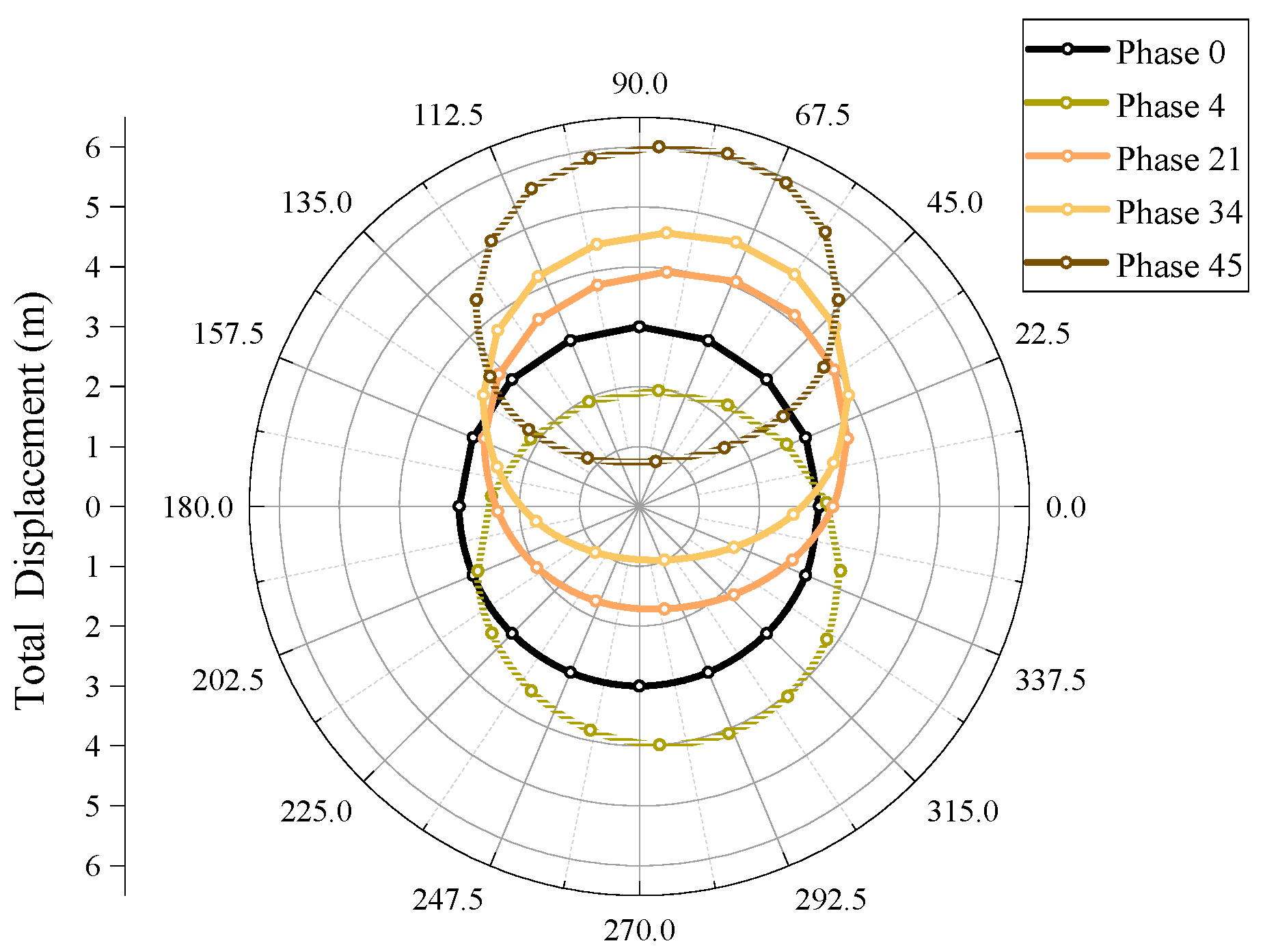
By transforming the global coordinate system to the position of the tunnel cross-section, a two-dimensional polar coordinate graph depicting the movement trend of the tunnel cross-section is presented in
Figure 14. This figure illustrates the movement trend of the tunnel cross-section under the comprehensive excavation plan, with the movement distances magnified by a factor of 5E3 for better visualization. The figure shows the initial state of the tunnel (Condition 0) located at the coordinate axis’s endpoint. After the construction of the diaphragm wall in preparation for excavation (Condition 4), the tunnel exhibits an overall trend toward the excavation pit and a slight sinking tendency. The tunnel structure’s out-of-roundness is relatively small during this process because the overall vertical and horizontal displacements are approximately equal, as indicated by
Figure 11 and
Figure 12. After excavation, the tunnel position continuously uplifts towards the excavation pit until the soil excavation is complete.
Figure 15 demonstrates that the initial movement trend of the tunnel is dominated by vertical and horizontal displacement in the early stages. As soil excavation commences, the increase in vertical uplift becomes more pronounced than the horizontal movement. In the polar coordinate graph, this is reflected by a more noticeable vertical uplift, highlighting the dominant role of vertical displacement in the later stages of excavation. The differing magnitudes of vertical and horizontal increases during soil excavation contribute to an increasing out-of-roundness in the tunnel structure. During the initial and first soil excavation step (Condition 4), the overall out-of-roundness of the tunnel structure is relatively small. As the excavation progresses, significant increases in the vertical and horizontal displacements near the pit-side measurement node result in slight differences in the position changes on either side of the tunnel nodes.
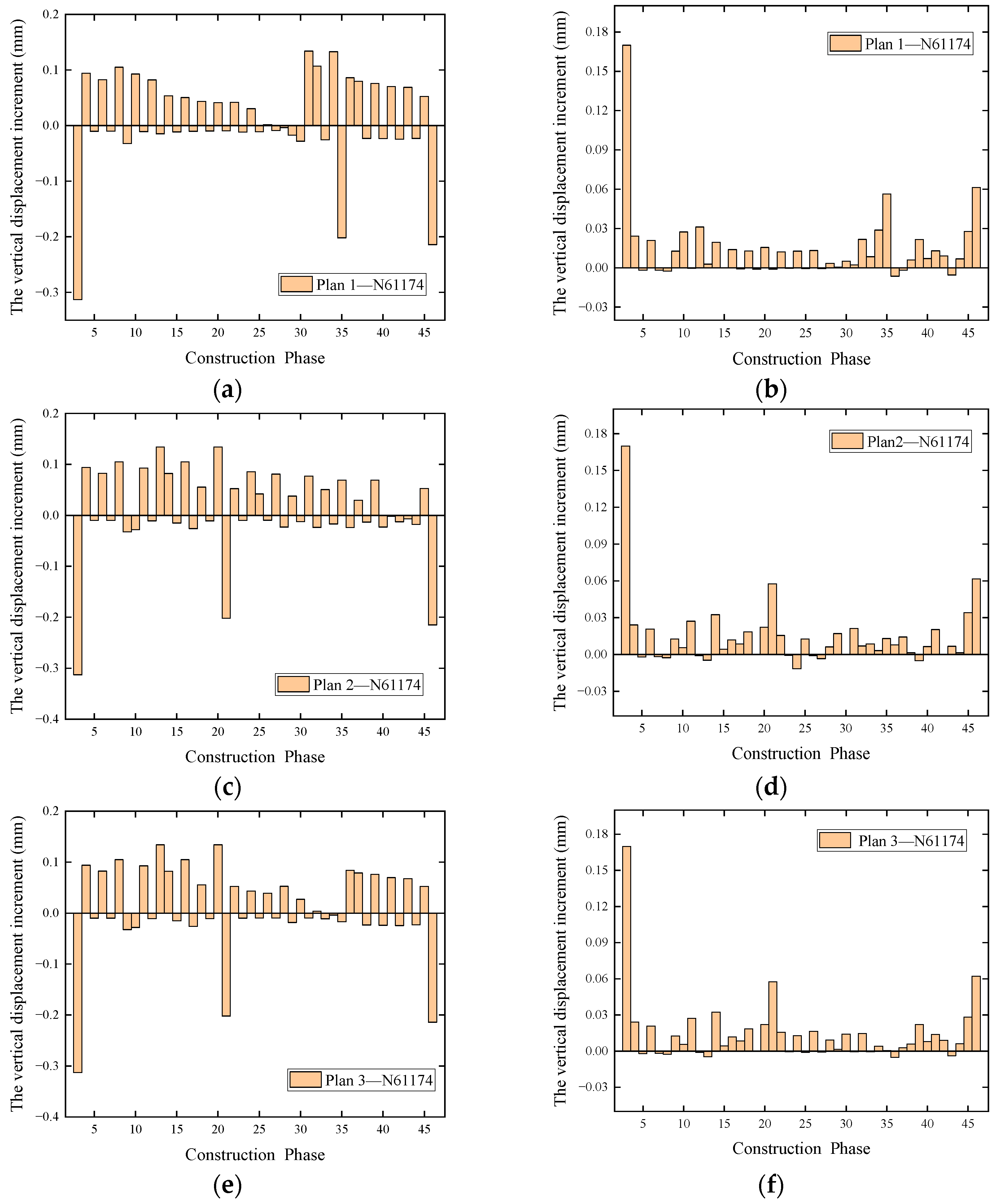
5.5. The Results of Incremental Displacement for Each Step of the Construction
The incremental displacements under various conditions for the three plans are illustrated in
Figure 15, taking the maximum displacement node N61174 as an example. The incremental displacement graph includes both vertical and horizontal displacement increments. Observing the figure, it is apparent that the vertical displacement increments and horizontal displacement increments resulting from the same condition differ by nearly an order of magnitude, with similar values for each displacement increment under all plans.
Simultaneously, it can be observed that the construction of concrete supports or ring beams can to some extent suppress the vertical uplift of the tunnel but has little effect on the horizontal increment. The construction of core zone plates and bottom plates can significantly inhibit the upward deformation of the tunnel in the vertical direction but increase the horizontal increment. Additionally, the construction of the diaphragm wall has an anti-uplift effect similar to that of the core zone plates and bottom plates, with a greater impact on the horizontal direction.


