
Status and Development Perspectives of the Compressed Air Energy Storage (CAES) Technologies—A Literature Review

 ,
,  , ,
, ,  ,
, 
Abstract
:1. Introduction
2. CAES Available Technologies
2.1. Diabatic (Fuel-Supplied) CAES
2.2. Adiabatic CAES
- A compression unit, composed of single or multiple compressors, capable of withstanding high temperatures of up to 700 °C;
- A cooling unit, absorbing the heat from the compressed air, reducing it to the required low-level temperature, and transferring the heat to thermal storage;
- Thermal storage capable of withstanding high temperatures;
- Compressed air storage, typically operating in the range of 40 to 90 bar;
- A heating unit, preheating the air before expansion;
- An expansion unit, composed of a single or multiple expanders.
- Cooling the compressed air to the lowest possible outlet temperature during the charging process and heating the compressed air to the highest possible outlet temperature during the discharge process;
- Maintaining a low-temperature variation of the air leaving the thermal storage.
- Minimizing the pressure loss during the operation,
- Low idle state losses.
2.3. Isothermal CAES
- Low-temperature air storage, either in an underground cavern or a tank;
- A compression unit, commonly a reciprocating engine with additional mechanisms to improve the heat transfer;
- An expansion unit with the same properties as the compressor.
2.4. Compressed Air Cars
2.5. Wave Energy Conversion through Air Compression
3. Air Storage Solutions
3.1. Underground Storage Chambers
3.2. Underwater Containers
3.3. Aboveground Vessels
4. Components of CAES Systems
4.1. Expanders
4.2. Compressors
4.3. Thermal Energy Storage
5. Existing CAES Installations
6. Summary on CAES Technologies and Comparison with Other Systems
6.1. General Characteristics of the Overviewed Compressed Air Storage Technologies
6.2. Performance and Expenditure Comparison of the CAES Electrical Storage Installations and Other EES Systems
7. Potential Perspectives for the CAES Technology
- Compression efficiency: This has a significant impact on the overall system efficiency. Modern compressor technologies, such as screw or turboprop compressors, offer a higher efficiency compared to traditional reciprocating compressors. Additional advancements can be achieved through isothermal compression technology.
- Expansion efficiency: This substantially affects the overall system efficiency. Modern expanders (both volumetric and dynamic) can achieve high levels of efficiency, contributing to a high CAES round-trip performance.
- Improved thermal insulation: Heat loss can be reduced during energy storage by using insulation materials with a high thermal efficiency.
- Development of heat recovery systems: High-efficiency heat exchangers can be used to recover heat released during the air compression and expansion.
- Optimization of adiabatic processes: Adiabatic processes that minimize heat energy loss by rapidly compressing and expanding air with minimal heat exchange with the environment can be used.
- Use of control and monitoring systems: Advanced control and monitoring systems that enable real-time optimization of the CAES system can be implemented.
- Integration with other technologies: Integrating the CAES system with other energy storage technologies and grid infrastructure can help increase its overall efficiency. For example, waste heat from the technological processes can be used to increase the temperature of the air during the expansion process.
8. Conclusions
- Turbines, along with centrifugal and axial compressors, represent mature and well-adapted technologies for medium- to large-scale CAES architectures (1 MWe–500 MWe).
- Positive displacement machines, including piston, screw, and scroll expanders–compressors, are well adapted to small- (<1 MWe) and micro-scale (<100 kWe) CAES applications.
- To achieve a low temperature (<200 °C) in the thermal storage tank in adiabatic CAES (A-CAES) systems, many interstage cooling units must be placed between the compression units, and a dedicated design of compressors is required.
- Achieving a very high air temperature (>600 °C) in an A-CAES system necessitates specialized compressor designs capable of withstanding high air temperatures and pressures.
- The cycle efficiency of A-CAES systems is largely affected by incorporated TES technology. The development and applicability of these systems depends on technological advancements in both fields.
- Compression–expansion under near-isothermal conditions can be achieved in piston-derived constructions with the use of such techniques as (1) liquid piston technology, (2) the injection of liquid or foam into the piston cylinder, and (3) structural modifications of the piston that take advantage of wire meshes or porous materials.
- The utilization of thermal storage is necessary to achieve a satisfactory level of round-trip efficiency.
- For large-scale electrical storage CAES systems, it is necessary to improve the capability of the element of thermal storage, especially by utilizing latent heat and thermochemical storage.
- The literature lacks studies describing the operation of CAES systems with latent heat and thermochemical heat storage, which justifies further projects.
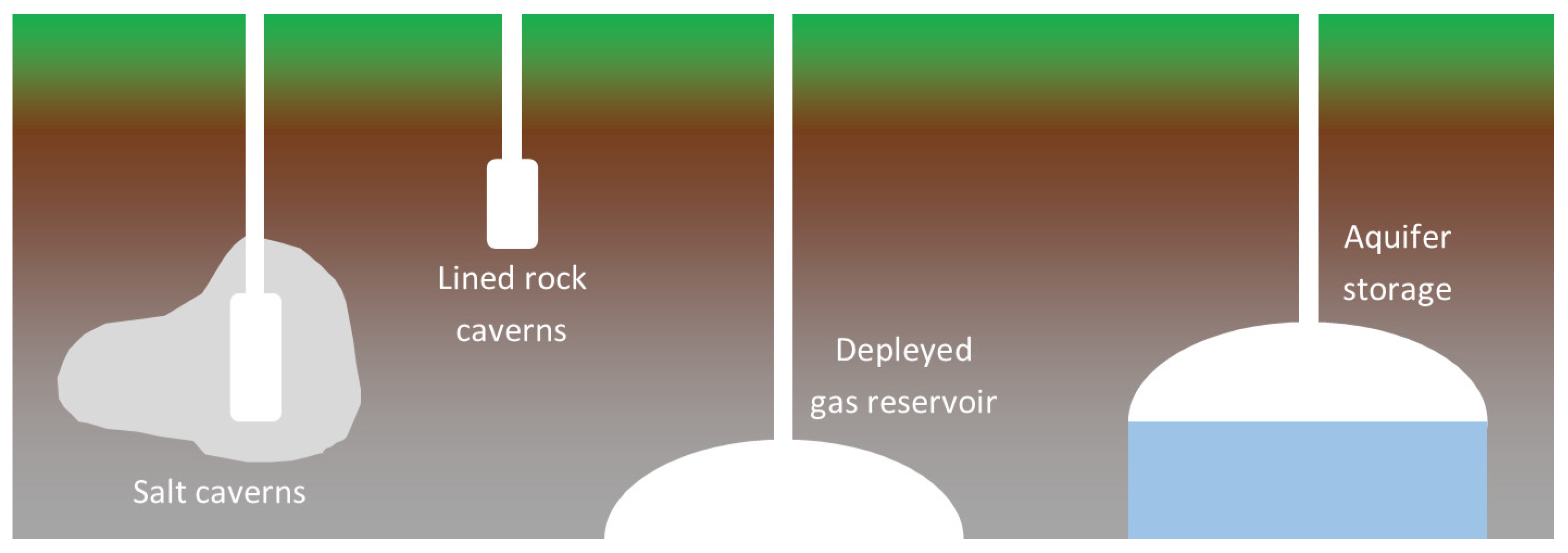
- A number of underground structures and techniques can be employed for the storage of compressed air, including the following four types: rock salt caves, abandoned mines, artificially excavated hard rock caverns, and aquifers. As a mature technology, salt caverns have been widely used. It has certain merits, such as a large capacity, higher storage pressure, and lower construction cost, compared to other storage technologies.
- The capital cost of electrical storage CAES installations using salt caverns is at least 10 times lower than that of aboveground installations.
- To increase the scalability and availability of the electrical storage CAES plants, it is possible to use aboveground compressed air vessels, making such systems more accessible to local power systems.
- Different innovative solutions based, for example, on the usage of hydrogen and solar energy vehicles using energy stored in compressed air produced by a compressor have also been suggested, being perceived as environmentally friendly and prospective vehicles.
- Research into efficiency improvements is needed to make CAES competitive with PHES for further development and deployment.
- Due to the increasing capacity of RESs, it is necessary to balance the system by absorbing surplus energy and supplementing the system in times of RES shortage. The large-scale use of CAES will make it possible to balance the electricity grid and avoid overloading it.
Author Contributions
Funding
Data Availability Statement
Acknowledgments
Conflicts of Interest
Abbreviations
| AA-CAES | advanced adiabatic compressed air energy storage |
| ADELE | Adiabater Druckluftspeicher für die Elektrizitätsversorgung |
| AOE | accumulated ocean energy |
| A-CAES | adiabatic compressed air energy storage |
| ASME | The American Society of Mechanical Engineers |
| C | compressor |
| CAES | compressed air energy storage |
| DOE | Department of Energy |
| D-CAES | diabatic compressed air energy storage |
| E | expander |
| EB | electrochemical battery |
| EES | electrical energy storage |
| G | generator |
| GT | gas turbine |
| IRENA | International Renewable Energy Agency |
| I-CAES | isothermal compressed air energy storage |
| LRC | lined rock cavern |
| M | motor |
| ORC | organic Rankine cycle |
| PCMs | phase change materials |
| PED | Pressure Equipment Directive |
| PHES | pumped hydroelectric energy storage |
| PV | photovoltaic panel |
| RESs | renewable energy sources |
| SF-CAES | supplementary-fueled compressed air energy storage |
| SRC | salt rock cavern |
| TES | thermal energy storage |
| TOPSIS | Technique for Order of Preference by Similarity to Ideal Solution |
| TUV | Technischer Überwachungsverein (Technical Inspection Association) |
| UWCAES | underwater compressed air-based energy storage |
| WT | wind turbine |
| W-CAES | wave-driven compressed air energy storage |
References
- This Publication Is a Preview of the Forthcoming Report, IRENA (2023), World Energy Transitions Outlook 2023: 1.5°C Pathway, International Renewable Energy Agency, Abu Dhabi. Available online: https://www.irena.org/-/media/Files/IRENA/Agency/Publication/2023/Mar/IRENA_WETO_Preview_2023.pdf?rev=2ca35086907b42cca651b0179a7c639c (accessed on 22 February 2024).
- The Evolution of Compressed Air. Quincy Compressor. Available online: https://www.quincycompressor.com/online-guides/evolution-compressed-air/ (accessed on 22 February 2024).
- Doug. A Quick History of the Air Compressor. Shop 3C Industrial. Available online: https://3cindustrial.net/2021/05/10/a-quick-history-of-the-air-compressor/ (accessed on 22 February 2024).
- The Editors of Encyclopedia Britannica. Mount Cenis Tunnel. Encyclopedia Britannica. 2021. Available online: https://www.britannica.com/biography/Germain-Sommeiller (accessed on 23 April 2024).
- Resilience. History and Future of the Compressed Air Economy. Resilience. Available online: https://www.resilience.org/stories/2018-05-16/history-and-future-of-the-compressed-air-economy/ (accessed on 22 February 2024).
- Ouellette, J. A Series of Tubes. Scientific American Blog Network. Available online: https://blogs.scientificamerican.com/cocktail-party-physics/httpblogsscientificamericancomcocktail-party-physics20110711a-series-of-tubes/ (accessed on 27 February 2024).
- Gay, F.W. Means for Storing Fluids for Power Generation. U.S. Patent 2433896, 6 January 1948. [Google Scholar]
- Budt, M.; Wolf, D.; Span, R.; Yan, J. A Review on Compressed Air Energy Storage: Basic Principles, Past Milestones and Recent Developments. Appl. Energy 2016, 170, 250–268. [Google Scholar] [CrossRef]
- Tawn, R.; Browell, J. A Review of Very Short-Term Wind and Solar Power Forecasting. Renew. Sustain. Energy Rev. 2022, 153, 111758. [Google Scholar] [CrossRef]
- Toufani, P.; Karakoyun, E.C.; Nadar, E.; Fosso, O.B.; Kocaman, A.S. Optimization of Pumped Hydro Energy Storage Systems under Uncertainty: A Review. J. Energy Storage 2023, 73, 109306. [Google Scholar] [CrossRef]
- Emrani, A.; Berrada, A.; Ameur, A.; Bakhouya, M. Assessment of the Round-Trip Efficiency of Gravity Energy Storage System: Analytical and Numerical Analysis of Energy Loss Mechanisms. J. Energy Storage 2022, 55, 105504. [Google Scholar] [CrossRef]
- Bazdar, E.; Sameti, M.; Nasiri, F.; Haghighat, F. Compressed Air Energy Storage in Integrated Energy Systems: A Review. Renew. Sustain. Energy Rev. 2022, 167, 112701. [Google Scholar] [CrossRef]
- Iurilli, P.; Luppi, L.; Brivio, C. Non-Invasive Detection of Lithium-Metal Battery Degradation. Energies 2022, 15, 6904. [Google Scholar] [CrossRef]
- Jafarizadeh, H.; Soltani, M.; Nathwani, J. Assessment of the Huntorf Compressed Air Energy Storage Plant Performance under Enhanced Modifications. Energy Convers. Manag. 2020, 209, 112662. [Google Scholar] [CrossRef]
- Wang, J.; Lu, K.; Ma, L.; Wang, J.; Dooner, M.; Miao, S.; Li, J.; Wang, D. Overview of Compressed Air Energy Storage and Technology Development. Energies 2017, 10, 991. [Google Scholar] [CrossRef]
- Kalhammer, F.R.; Schneider, T.R. Energy Storage. Annu. Rev. Energy 1976, 1, 311–343. [Google Scholar] [CrossRef]
- Foley, A.; Díaz Lobera, I. Impacts of Compressed Air Energy Storage Plant on an Electricity Market with a Large Renewable Energy Portfolio. Energy 2013, 57, 85–94. [Google Scholar] [CrossRef]
- Borri, E.; Tafone, A.; Comodi, G.; Romagnoli, A.; Cabeza, L.F. Compressed Air Energy Storage—An Overview of Research Trends and Gaps through a Bibliometric Analysis. Energies 2022, 15, 7692. [Google Scholar] [CrossRef]
- Li, Y.; Hong, F.; Ge, X.; Zhang, X.; Zhao, B.; Wu, F. Optimal Capacity Configuration of Pumped-Storage Units Used to Retrofit Cascaded Hydropower Stations. Energies 2023, 16, 8049. [Google Scholar] [CrossRef]
- Santos, A.S.; Faria, L.T.; Lopes, M.L.M.; Minussi, C.R. Power Distribution Systems’ Vulnerability by Regions Caused by Electrical Discharges. Energies 2023, 16, 7790. [Google Scholar] [CrossRef]
- Li, P.Y. Isothermal Compressed Air Energy Storage (i-CAES) System. In Encyclopedia of Energy Storage; Elsevier: Amsterdam, The Netherlands, 2022; pp. 204–217. [Google Scholar]
- Chen, L.; Wang, Y.; Xie, M.; Ye, K.; Mohtaram, S. Energy and Exergy Analysis of Two Modified Adiabatic Compressed Air Energy Storage (A-CAES) System for Cogeneration of Power and Cooling on the Base of Volatile Fluid. J. Energy Storage 2021, 42, 103009. [Google Scholar] [CrossRef]
- Salvini, C.; Giovannelli, A. Techno-Economic Comparison of Diabatic CAES with Artificial Air Reservoir and Battery Energy Storage Systems. Energy Rep. 2022, 8, 601–607. [Google Scholar] [CrossRef]
- Mou, J.; Shang, H.; Ji, W.; Wan, J.; Xing, T.; Ma, H.; Peng, W. Feasibility Analysis of Compressed Air Energy Storage in Salt Caverns in the Yunying Area. Energies 2023, 16, 7171. [Google Scholar] [CrossRef]
- Zhang, J.; Zhou, S.; Li, S.; Song, W.; Feng, Z. Performance Analysis of Diabatic Compressed Air Energy Storage (D-CAES) System. Energy Procedia 2019, 158, 4369–4374. [Google Scholar] [CrossRef]
- Soltani, M.; Moradi Kashkooli, F.; Jafarizadeh, H.; Hatefi, M.; Fekri, H.; Gharali, K.; Nathwani, J. Diabatic Compressed Air Energy Storage (CAES) Systems: State of the Art. In Encyclopedia of Energy Storage; Elsevier: Amsterdam, The Netherlands, 2022; pp. 173–187. [Google Scholar]
- Barnes, F.S.; Levine, J.G. Large Energy Storage Systems Handbook, 1st ed.; CRC Press: Boca Raton, FL, USA, 2017. [Google Scholar]
- Sterner, M.; Stadler, I. (Eds.) Handbook of Energy Storage: Demand, Technologies, Integration, 1st ed.; Springer: Berlin/Heidelberg, Germany, 2019. [Google Scholar]
- Rabi, A.; Radulovic, J.; Buick, J. Comprehensive Review of Compressed Air Energy Storage (CAES) Technologies. Thermo 2023, 3, 104–126. [Google Scholar] [CrossRef]
- Geissbühler, L.; Becattini, V.; Zanganeh, G.; Zavattoni, S.; Barbato, M.; Haselbacher, A.; Steinfeld, A. Pilot-Scale Demonstration of Advanced Adiabatic Compressed Air Energy Storage, Part 1: Plant Description and Tests with Sensible Thermal-Energy Storage. J. Energy Storage 2018, 17, 129–139. [Google Scholar] [CrossRef]
- Li, Y.; Miao, S.; Yin, B.; Han, J.; Zhang, S.; Wang, J.; Luo, X. Combined Heat and Power Dispatch Considering Advanced Adiabatic Compressed Air Energy Storage for Wind Power Accommodation. Energy Convers. Manag. 2019, 200, 112091. [Google Scholar] [CrossRef]
- Grazzini, G.; Milazzo, A. A Thermodynamic Analysis of Multistage Adiabatic CAES. Proc. IEEE Inst. Electr. Electron. Eng. 2012, 100, 461–472. [Google Scholar] [CrossRef]
- Irena.org. Available online: https://www.irena.org/-/media/Files/IRENA/Agency/Publication/2013/IRENA-ETSAP-Tech-Brief-E17-Thermal-Energy-Storage.pdf (accessed on 27 February 2024).
- Thomasson, T.; Tähtinen, M.; Tapani, A.; Sihvonen, T. Dynamic Analysis of Adiabatic CAES with Electric Resistance Heating. Energy Procedia 2017, 135, 464–471. [Google Scholar] [CrossRef]
- Xue, H.; White, A. A Comparative Study of Liquid, Solid and Hybrid Adiabatic Compressed Air Energy Storage Systems. J. Energy Storage 2018, 18, 349–359. [Google Scholar] [CrossRef]
- Mitali, J.; Dhinakaran, S.; Mohamad, A.A. Energy Storage Systems: A Review. Energy Storage Sav. 2022, 1, 166–216. [Google Scholar] [CrossRef]
- Li, X.; Xu, E.; Song, S.; Wang, X.; Yuan, G. Dynamic Simulation of Two-Tank Indirect Thermal Energy Storage System with Molten Salt. Renew. Energy 2017, 113, 1311–1319. [Google Scholar] [CrossRef]
- Nilsson, M. Simplified Pumped Thermal Energy Storage Using a Two-Way Stirling Cycle. J. Energy Storage 2023, 73, 108994. [Google Scholar] [CrossRef]
- Valenti, G.; Valenti, A.; Staboli, S. Proposal of a Thermally-Driven Air Compressor for Waste Heat Recovery. Energy Convers. Manag. 2019, 196, 1113–1125. [Google Scholar] [CrossRef]
- Jaroslaw, M.; Badyda, K.; Szabłowski, Ł. Compressed Air Energy Storage Systems. J. Power Technol. 2016, 96, 245–260. [Google Scholar]
- Kushnir, R.; Dayan, A.; Ullmann, A. Temperature and Pressure Variations within Compressed Air Energy Storage Caverns. Int. J. Heat Mass Transf. 2012, 55, 5616–5630. [Google Scholar] [CrossRef]
- He, W.; Wang, J.; Wang, Y.; Ding, Y.; Chen, H.; Wu, Y.; Garvey, S. Study of Cycle-to-Cycle Dynamic Characteristics of Adiabatic Compressed Air Energy Storage Using Packed Bed Thermal Energy Storage. Energy 2017, 141, 2120–2134. [Google Scholar] [CrossRef]
- Saigustia, C.; Robak, S. Review of Potential Energy Storage in Abandoned Mines in Poland. Energies 2021, 14, 6272. [Google Scholar] [CrossRef]
- He, W.; Wang, J. Optimal Selection of Air Expansion Machine in Compressed Air Energy Storage: A Review. Renew. Sustain. Energy Rev. 2018, 87, 77–95. [Google Scholar] [CrossRef]
- RWE. RWE Power AG. Rwe.com. Available online: http://www.rwe.com/rwepower (accessed on 27 February 2024).
- Barbour, E.R.; Pottie, D.L.; Eames, P. Why Is Adiabatic Compressed Air Energy Storage yet to Become a Viable Energy Storage Option? iScience 2021, 24, 102440. [Google Scholar] [CrossRef]
- Wang, S.; Zhang, X.; Yang, L.; Zhou, Y.; Wang, J. Experimental Study of Compressed Air Energy Storage System with Thermal Energy Storage. Energy 2016, 103, 182–191. [Google Scholar] [CrossRef]
- Design Study for the European Underground Research Infra-Structure Related to Advanced Adiabatic Compressed Air Energy Storage. CORDIS—European Commission. Available online: https://cordis.europa.eu/project/id/654387/reporting (accessed on 27 February 2024).
- CAES. Siemens-Energy.Com. Available online: https://www.siemens-energy.com/global/en/home/products-services/product/caes.html (accessed on 27 February 2024).
- Jiangsu Salt Cavern Compressed Air Energy Storage Project Put into Operation—Seetao. Seetao.com. Available online: https://www.seetao.com/details/159902.html (accessed on 27 February 2024).
- Jintan Salt Cave Compressed Air Energy Storage Project, a National Pilot Demonstration Project Co-Developed by Tsinghua University, Passed the Grid Incorporation Test-Department of Electrical Engineering Tsinghua University. Edu.cn. Available online: https://0-www-eea-tsinghua-edu-cn.brum.beds.ac.uk/en/info/1038/2062.htm (accessed on 25 February 2024).
- MAN Energy Solutions Isothermal Compressors. MAN Energy Solutions. Available online: https://www.man-es.com/process-industry/products/compressors/isothermal (accessed on 27 February 2024).
- Mitra, S.; Mahato, A.C.; Nag, A.; Kumar, D. Various Methodologies to Improve the Energy Efficiency of a Compressed Air Energy Storage System. Energy Storage 2022, 4, e315. [Google Scholar] [CrossRef]
- Olabi, A.G.; Wilberforce, T.; Ramadan, M.; Abdelkareem, M.A.; Alami, A.H. Compressed Air Energy Storage Systems: Components and Operating Parameters—A Review. J. Energy Storage 2021, 34, 102000. [Google Scholar] [CrossRef]
- Hal.science. Available online: https://hal.science/tel-03658533 (accessed on 27 February 2024).
- Yu, Q.; Wang, Q.; Tan, X.; Li, X. Water Spray Heat Transfer Gas Compression for Compressed Air Energy System. Renew. Energy 2021, 179, 1106–1121. [Google Scholar] [CrossRef]
- Energy Systems and Energy Storage Lab. Eseslab.Com. Available online: http://www.eseslab.com/posts/blogPost_lightsail_hibernates (accessed on 27 February 2024).
- Available online: https://www.enbook.pl/catalog/product/view/id/472940?gad_source=1&gclid=Cj0KCQiA5-uuBhDzARIsAAa21T_QlauGdSIKhgqbxdB2qejibWeVVP2oCvPlcmhBruk_L-RGToZ7Q0QaAhYFEALw_wcB (accessed on 27 February 2024).
- Kim, T.; Lee, C.-Y.; Hwang, Y.; Radermacher, R. A Review on Nearly Isothermal Compression Technology. Int. J. Refrig. 2022, 144, 145–162. [Google Scholar] [CrossRef]
- Ko, J.; Kim, S.; Kim, S.; Seo, H. Performance of a Compressed-Air Energy Storage Pile under Various Operation Conditions. J. Energy Storage 2023, 57, 106194. [Google Scholar] [CrossRef]
- Stanford.Edu. Available online: http://large.stanford.edu/courses/2015/ph240/burnett2/docs/bollinger.pdf (accessed on 27 February 2024).
- REMORA. Segula Technologies. Available online: https://www.segulatechnologies.com/en/innovation_project/remora/ (accessed on 27 February 2024).
- Candelaresi, D.; Valente, A.; Iribarren, D.; Dufour, J.; Spazzafumo, G. Comparative Life Cycle Assessment of Hydrogen-Fuelled Passenger Cars. Int. J. Hydrogen Energy 2021, 46, 35961–35973. [Google Scholar] [CrossRef]
- Ho, T.; Karri, V. Hydrogen Powered Car: Two-Stage Modelling System. Int. J. Hydrogen Energy 2011, 36, 10065–10079. [Google Scholar] [CrossRef]
- Mathijsen, D. The Role of Composites in Getting the Solar Car to Our Driveways: Lightyear One. Reinf. Plast. 2021, 65, 178–187. [Google Scholar] [CrossRef]
- Sornek, K.; Wiercioch, J.; Kurczyna, D.; Figaj, R.; Wójcik, B.; Borowicz, M.; Wieliński, M. Development of a Solar-Powered Small Autonomous Surface Vehicle for Environmental Measurements. Energy Convers. Manag. 2022, 267, 115953. [Google Scholar] [CrossRef]
- Scholars, S.; Mishra, K.R.; Sugandh, G. Study about Engine Operated by Compressed Air (C.a.e): A Pneumatic Power Source. IOSR J. Mech. Civ. Eng. 2014, 11, 99–103. [Google Scholar] [CrossRef]
- Creutzig, F.; Papson, A.; Schipper, L.; Kammen, D.M. Economic and Environmental Evaluation of Compressed-Air Cars. Environ. Res. Lett. 2009, 4, 044011. [Google Scholar] [CrossRef]
- Fang, Y.; Lu, Y.; Roskilly, A.P.; Yu, X. A Review of Compressed Air Energy Systems in Vehicle Transport. Energy Strat. Rev. 2021, 33, 100583. [Google Scholar] [CrossRef]
- Wasbari, F.; Bakar, R.A.; Gan, L.M.; Tahir, M.M.; Yusof, A.A. A Review of Compressed-Air Hybrid Technology in Vehicle System. Renew. Sustain. Energy Rev. 2017, 67, 935–953. [Google Scholar] [CrossRef]
- Korbut, M.; Szpica, D. A Review of Compressed Air Engine in the Vehicle Propulsion System. Acta Mech. Autom. 2021, 15, 215–226. [Google Scholar] [CrossRef]
- Zhai, X.; Yu, X.L.; Cai, J.L.; Shen, Y.M. Experimental Study on Performances of Compressed-Air Engine. J. Zhejiang Univ. Eng. Sci 2006, 4, 135–138. [Google Scholar]
- Huang, C.-Y.; Hu, C.-K.; Yu, C.-J.; Sung, C.-K. Experimental Investigation on the Performance of a Compressed-Air Driven Piston Engine. Energies 2013, 6, 1731–1745. [Google Scholar] [CrossRef]
- Nabil, T. Investigation and Implementation of Compressed Air Powered Motorbike Engines. Eng. Rep. 2019, 1, e12034. [Google Scholar] [CrossRef]
- Asrar, M. Report: Tata Nano to Spawn Electric, Hybrid & Air-Powered Variants. BharathAutos—Automobile News Updates. Available online: https://bharathautos.com/tata-nano-petrol-diesel-electric-hybrid-air-power-cars.html (accessed on 25 February 2024).
- European Publication Server. Epo.org. Available online: https://www.epo.org/en/searching-for-patents/technical/publication-server (accessed on 27 February 2024).
- Evrin, R.A.; Dincer, I. Experimental Investigation of a Compressed Air Vehicle Prototype with Phase Change Materials for Heat Recovery. Energy Storage 2020, 2, e159. [Google Scholar] [CrossRef]
- Suranjan, S.; Valladares, J.; Pereira, C.M.; Sreedharan, A.S.; Sabin, N.; Sachidananda, H.K. Design of a Compressed Air Vehicle. Int. J. Innov. Technol. Explor. Eng. 2019, 9, 4816–4823. [Google Scholar] [CrossRef]
- Xu, Y.; Wang, X.; Zhang, H.; Yang, F.; Liang, J.; Yang, H.; Niu, K.; Liu, Z.; Wang, Y.; Wu, Y. Experimental Investigation of the Output Performance of Compressed-Air-Powered Vehicles with a Pneumatic Motor. Sustainability 2022, 14, 15377. [Google Scholar] [CrossRef]
- Dobrovský, P. Pneumobil: Auto Na Vzduch. abicko.cz. Available online: https://www.abicko.cz/clanek/precti-si-technika-auta/22199/pneumobil-auto-na-vzduch.html (accessed on 25 February 2024).
- Rudo. Pneumobil. Tuke.sk. Available online: https://www.sjf.tuke.sk/kr/katedra/aktuality/pneumobil (accessed on 25 February 2024).
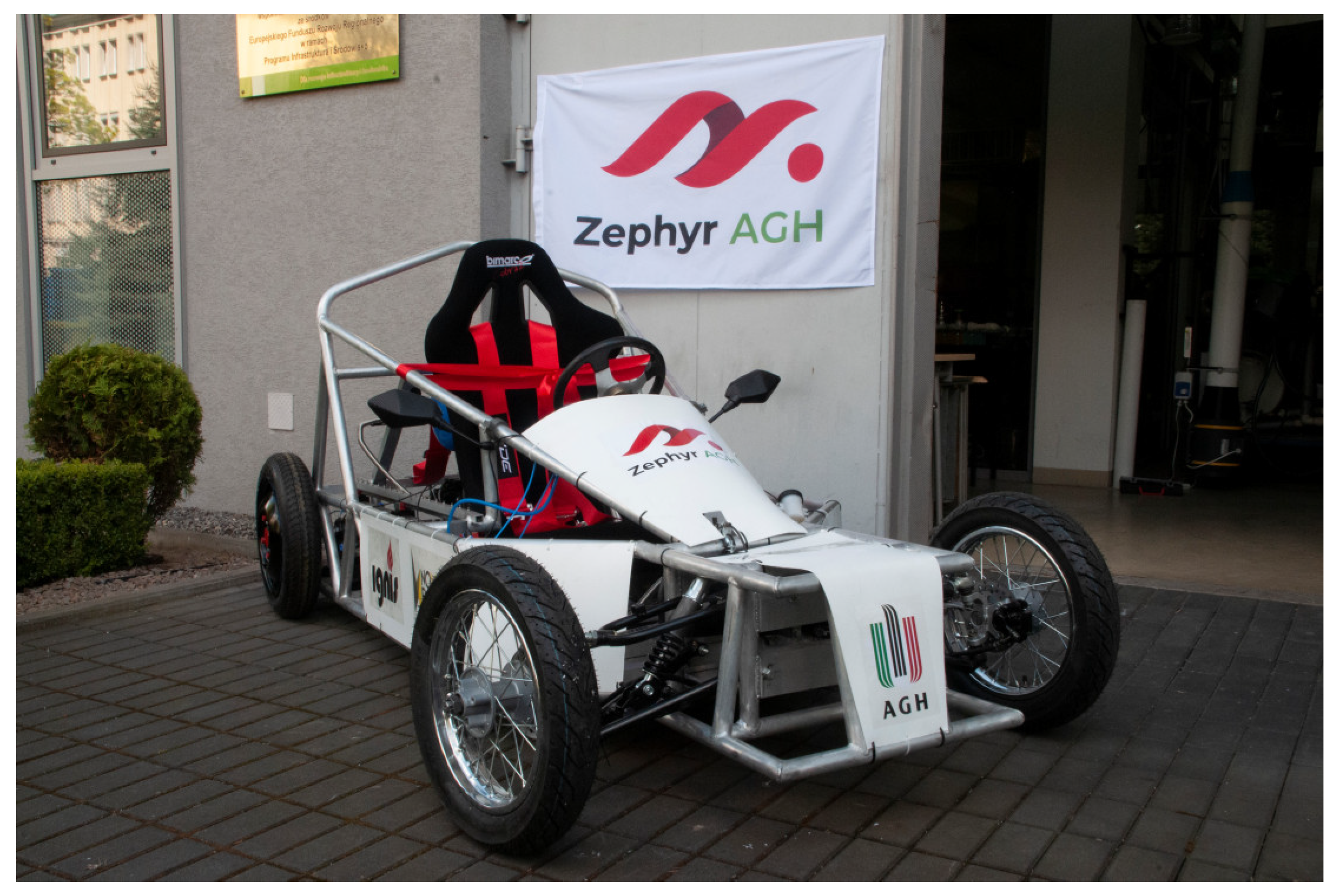
- Zephyr AGH—Nova Energia. Edu.pl. Available online: http://www.novaenergia.agh.edu.pl/zephyr-agh/ (accessed on 25 February 2024).
- Ssrn.com. Available online: https://papers.ssrn.com/sol3/papers.cfm?abstract_id=3688425 (accessed on 25 February 2024).
- Shi, Y.; Li, F.; Cai, M.; Yu, Q. Literature Review: Present State and Future Trends of Air-Powered Vehicles. J. Renew. Sustain. Energy 2016, 8, e4944970. [Google Scholar] [CrossRef]
- Brown, T.L.; Atluri, V.P.; Schmiedeler, J.P. A Low-Cost Hybrid Drivetrain Concept Based on Compressed Air Energy Storage. Appl. Energy 2014, 134, 477–489. [Google Scholar] [CrossRef]
- Yi, T.; Ma, F.; Jin, C.; Huang, Y. A Novel Coupled Hydro-Pneumatic Energy Storage System for Hybrid Mining Trucks. Energy 2018, 143, 704–718. [Google Scholar] [CrossRef]
- Bravo, R.R.S.; De Negri, V.J.; Oliveira, A.A.M. Design and Analysis of a Parallel Hydraulic—Pneumatic Regenerative Braking System for Heavy-Duty Hybrid Vehicles. Appl. Energy 2018, 225, 60–77. [Google Scholar] [CrossRef]
- Qiao, D.; Haider, R.; Yan, J.; Ning, D.; Li, B. Review of Wave Energy Converter and Design of Mooring System. Sustainability 2020, 12, 8251. [Google Scholar] [CrossRef]
- Ma, S.; Wang, X.; Negnevitsky, M.; Franklin, E. Performance Investigation of a Wave-Driven Compressed Air Energy Storage System. J. Energy Storage 2023, 73, 109126. [Google Scholar] [CrossRef]
- Lawes, R. Wave Driven Air Compressor. U.S. Patent 20110158827:A1, 30 June 2011. [Google Scholar]
- AOE—Accumulated Ocean Energy Inc. Available online: https://aoewave.com/technology (accessed on 27 February 2024).
- Kim, H.-M.; Rutqvist, J.; Ryu, D.-W.; Choi, B.-H.; Sunwoo, C.; Song, W.-K. Exploring the Concept of Compressed Air Energy Storage (CAES) in Lined Rock Caverns at Shallow Depth: A Modeling Study of Air Tightness and Energy Balance. Appl. Energy 2012, 92, 653–667. [Google Scholar] [CrossRef]
- Wei, X.; Ban, S.; Shi, X.; Li, P.; Li, Y.; Zhu, S.; Yang, K.; Bai, W.; Yang, C. Carbon and Energy Storage in Salt Caverns under the Background of Carbon Neutralization in China. Energy 2023, 272, 127120. [Google Scholar] [CrossRef]
- Li, P.; Kang, H.; Zhu, Q.; Wu, Y.; Zhang, J.; Fan, L.; Wang, Z. Numerical and Experimental Investigations of Concrete Lined Compressed Air Energy Storage System. J. Clean. Prod. 2023, 390, 136153. [Google Scholar] [CrossRef]
- Chen, X.; Wang, J.G. Stability Analysis for Compressed Air Energy Storage Cavern with Initial Excavation Damage Zone in an Abandoned Mining Tunnel. J. Energy Storage 2022, 45, 103725. [Google Scholar] [CrossRef]
- Li, Y.; Li, Y.; Liu, Y. Numerical Study on the Impacts of Layered Heterogeneity on the Underground Process in Compressed Air Energy Storage in Aquifers. J. Energy Storage 2022, 46, 103837. [Google Scholar] [CrossRef]
- Donadei, S.; Schneider, G.-S. Compressed Air Energy Storage. In Storing Energy; Elsevier: Amsterdam, The Netherlands, 2022; pp. 141–156. [Google Scholar]
- Donadei, S.; Schneider, G.-S. Compressed Air Energy Storage in Underground Formations. In Storing Energy; Elsevier: Amsterdam, The Netherlands, 2016; pp. 113–133. [Google Scholar]
- Matos, C.R.; Carneiro, J.F.; Silva, P.P. Overview of Large-Scale Underground Energy Storage Technologies for Integration of Renewable Energies and Criteria for Reservoir Identification. J. Energy Storage 2019, 21, 241–258. [Google Scholar] [CrossRef]
- Crotogino, F.; Schneider, G.-S.; Evans, D.J. Renewable Energy Storage in Geological Formations. Proc. Inst. Mech. Eng. A J. Power Energy 2018, 232, 100–114. [Google Scholar] [CrossRef]
- Fan, J.; Liu, W.; Jiang, D.; Chen, J.; Ngaha Tiedeu, W.; Chen, J.; Jjk, D. Thermodynamic and Applicability Analysis of a Hybrid CAES System Using Abandoned Coal Mine in China. Energy 2018, 157, 31–44. [Google Scholar] [CrossRef]
- Kim, H.-M.; Rutqvist, J.; Kim, H.; Park, D.; Ryu, D.-W.; Park, E.-S. Failure Monitoring and Leakage Detection for Underground Storage of Compressed Air Energy in Lined Rock Caverns. Rock Mech. Rock Eng. 2016, 49, 573–584. [Google Scholar] [CrossRef]
- Yin, H.; Yang, C.; Ma, H.; Shi, X.; Zhang, N.; Ge, X.; Li, H.; Han, Y. Stability Evaluation of Underground Gas Storage Salt Caverns with Micro-Leakage Interlayer in Bedded Rock Salt of Jintan, China. Acta Geotech. 2020, 15, 549–563. [Google Scholar] [CrossRef]
- Evans, D.; Reay, D.; Riley, N.; Mitchell, W.; Busby, J. Appraisal of Underground Energy Storage Potential in Northern Ireland. 2006. Available online: https://www2.bgs.ac.uk/gsni/energy/storage/Appraisal%20of%20underground%20energy%20storage%20potential%20in%20Northern%20Ireland%20-%20BGS.pdf (accessed on 23 April 2024).
- Wu, F.; Liu, Y.; Gao, R. Challenges and Opportunities of Energy Storage Technology in Abandoned Coal Mines: A Systematic Review. J. Energy Storage 2024, 83, 110613. [Google Scholar] [CrossRef]
- Rutqvist, J.; Kim, H.-M.; Ryu, D.-W.; Synn, J.-H.; Song, W.-K. Modeling of Coupled Thermodynamic and Geomechanical Performance of Underground Compressed Air Energy Storage in Lined Rock Caverns. Int. J. Rock Mech. Min. Sci. 2012, 52, 71–81. [Google Scholar] [CrossRef]
- King, M.; Jain, A.; Bhakar, R.; Mathur, J.; Wang, J. Overview of Current Compressed Air Energy Storage Projects and Analysis of the Potential Underground Storage Capacity in India and the UK. Renew. Sustain. Energy Rev. 2021, 139, 110705. [Google Scholar] [CrossRef]
- Wang, T.; Yang, C.; Wang, H.; Ding, S.; Daemen, J.J.K. Debrining Prediction of a Salt Cavern Used for Compressed Air Energy Storage. Energy 2018, 147, 464–476. [Google Scholar] [CrossRef]
- Ozarslan, A. Large-Scale Hydrogen Energy Storage in Salt Caverns. Int. J. Hydrogen Energy 2012, 37, 14265–14277. [Google Scholar] [CrossRef]
- Parkes, D.; Evans, D.J.; Williamson, P.; Williams, J.D.O. Estimating Available Salt Volume for Potential CAES Development: A Case Study Using the Northwich Halite of the Cheshire Basin. J. Energy Storage 2018, 18, 50–61. [Google Scholar] [CrossRef]
- Menéndez, J.; Fernández-Oro, J.M.; Galdo, M.; Álvarez, L.; Bernardo-Sánchez, A. Numerical Investigation of Underground Reservoirs in Compressed Air Energy Storage Systems Considering Different Operating Conditions: Influence of Thermodynamic Performance on the Energy Balance and Round-Trip Efficiency. J. Energy Storage 2022, 46, 103816. [Google Scholar] [CrossRef]
- Chen, L.-X.; Hu, P.; Sheng, C.-C.; Xie, M.-N. A Novel Compressed Air Energy Storage (CAES) System Combined with Pre-Cooler and Using Low Grade Waste Heat as Heat Source. Energy 2017, 131, 259–266. [Google Scholar] [CrossRef]
- Sant, T.; Buhagiar, D.; Farrugia, R.N. Evaluating a New Concept to Integrate Compressed Air Energy Storage in Spar-Type Floating Offshore Wind Turbine Structures. Ocean Eng. 2018, 166, 232–241. [Google Scholar] [CrossRef]
- Zhang, X.; Gao, Z.; Zhou, B.; Guo, H.; Xu, Y.; Ding, Y.; Chen, H. Advanced Compressed Air Energy Storage Systems: Fundamentals and Applications. Engineering 2024. [Google Scholar] [CrossRef]
- Maisonnave, O.; Moreau, L.; Aubrée, R.; Benkhoris, M.-F.; Neu, T.; Guyomarc’h, D. Optimal Energy Management of an Underwater Compressed Air Energy Storage Station Using Pumping Systems. Energy Convers. Manag. 2018, 165, 771–782. [Google Scholar] [CrossRef]
- Pimm, A.J.; Garvey, S.D.; de Jong, M. Design and Testing of Energy Bags for Underwater Compressed Air Energy Storage. Energy 2014, 66, 496–508. [Google Scholar] [CrossRef]
- Laing, O.; Laing, J.L.N. Energy Storage for off Peak Electricity. U.S. Patent 4873828, 17 October 1989. [Google Scholar]
- Wang, Z.; Ting, D.S.-K.; Carriveau, R.; Xiong, W.; Wang, Z. Design and Thermodynamic Analysis of a Multi-Level Underwater Compressed Air Energy Storage System. J. Energy Storage 2016, 5, 203–211. [Google Scholar] [CrossRef]
- Cheung, B.C.; Carriveau, R.; Ting, D.S.-K. Parameters Affecting Scalable Underwater Compressed Air Energy Storage. Appl. Energy 2014, 134, 239–247. [Google Scholar] [CrossRef]
- Frate, G.F.; Ferrari, L.; Desideri, U. Energy Storage for Grid-Scale Applications: Technology Review and Economic Feasibility Analysis. Renew. Energy 2021, 163, 1754–1772. [Google Scholar] [CrossRef]
- Rodrigues, S.; Restrepo, C.; Kontos, E.; Teixeira Pinto, R.; Bauer, P. Trends of Offshore Wind Projects. Renew. Sustain. Energy Rev. 2015, 49, 1114–1135. [Google Scholar] [CrossRef]
- Wang, Z.; Xiong, W.; Ting, D.S.-K.; Carriveau, R.; Wang, Z. Comparison of Underwater and Underground CAES Systems for Integrating Floating Offshore Wind Farms. J. Energy Storage 2017, 14, 276–282. [Google Scholar] [CrossRef]
- Olympios, A.V.; McTigue, J.D.; Farres-Antunez, P.; Tafone, A.; Romagnoli, A.; Li, Y.; Ding, Y.; Steinmann, W.-D.; Wang, L.; Chen, H.; et al. Progress and Prospects of Thermo-Mechanical Energy Storage—A Critical Review. Prog. Energy 2021, 3, 022001. [Google Scholar] [CrossRef]
- Liu, J.; Zhang, X.; Xu, Y.; Chen, Z.; Chen, H.; Tan, C. Economic Analysis of Using above Ground Gas Storage Devices for Compressed Air Energy Storage System. J. Therm. Sci. 2014, 23, 535–543. [Google Scholar] [CrossRef]
- Sim, L.C.; Yeo, W.H.; Purbolaksono, J.; Saw, L.H.; Tey, J.Y. Analytical Solution of Thermo-Mechanical Stresses of Multi-Layered Hollow Spherical Pressure Vessel. Int. J. Pressure Vessels Piping 2021, 191, 104355. [Google Scholar] [CrossRef]
- Li, J.; Huang, F.; Tu, C.; Tian, M.; Wang, X. Elastic Obstacle-Surmounting Pipeline-Climbing Robot with Composite Wheels. Machines 2022, 10, 874. [Google Scholar] [CrossRef]
- Supply, G.P. CAES Energy Storage. Globalpwr.com. Available online: https://www.globalpwr.com/wp-content/uploads/cut-sheets/gps-compressed-air-energy-storage-caes-technology.pdf (accessed on 23 February 2024).
- Handbook of Energy Storage for Transmission or Distribution Applications; EPRI: Palo Alto, CA, USA, 2002.
- Matos, C.R.; Silva, P.P.; Carneiro, J.F. Overview of Compressed Air Energy Storage Projects and Regulatory Framework for Energy Storage. J. Energy Storage 2022, 55, 105862. [Google Scholar] [CrossRef]
- Bollinger, B. Demonstration of Isothermal Compressed Air Energy Storage to Support Renewable Energy Production; Office of Scientific and Technical Information (OSTI): Oak Ridge, TN, USA, 2015.
- Mei, S.; Wang, J.; Tian, F.; Chen, L.; Xue, X.; Lu, Q.; Zhou, Y.; Zhou, X. Design and Engineering Implementation of Non-Supplementary Fired Compressed Air Energy Storage System: TICC-500. Sci. China Technol. Sci. 2015, 58, 600–611. [Google Scholar] [CrossRef]
- Meroni, A.; Andreasen, J.G.; Persico, G.; Haglind, F. Optimization of Organic Rankine Cycle Power Systems Considering Multistage Axial Turbine Design. Appl. Energy 2018, 209, 339–354. [Google Scholar] [CrossRef]
- Witanowski, Ł.; Klonowicz, P.; Lampart, P.; Suchocki, T.; Jędrzejewski, Ł.; Zaniewski, D.; Klimaszewski, P. Optimization of an Axial Turbine for a Small Scale ORC Waste Heat Recovery System. Energy 2020, 205, 118059. [Google Scholar] [CrossRef]
- Jankowski, M.; Borsukiewicz, A.; Hooman, K. Development of Decision-Making Tool and Pareto Set Analysis for Bi-Objective Optimization of an ORC Power Plant. Energies 2020, 13, 5280. [Google Scholar] [CrossRef]
- Witanowski, Ł.; Ziółkowski, P.; Klonowicz, P.; Lampart, P. A Hybrid Approach to Optimization of Radial Inflow Turbine with Principal Component Analysis. Energy 2023, 272, 127064. [Google Scholar] [CrossRef]
- Wolf, D.; Budt, M. LTA-CAES—A Low-Temperature Approach to Adiabatic Compressed Air Energy Storage. Appl. Energy 2014, 125, 158–164. [Google Scholar] [CrossRef]
- Luo, X.; Wang, J.; Dooner, M.; Clarke, J.; Krupke, C. Overview of Current Development in Compressed Air Energy Storage Technology. Energy Procedia 2014, 62, 603–611. [Google Scholar] [CrossRef]
- Ibrahim, H.; Belmokhtar, K.; Ghandour, M. Investigation of Usage of Compressed Air Energy Storage for Power Generation System Improving—Application in a Microgrid Integrating Wind Energy. Energy Procedia 2015, 73, 305–316. [Google Scholar] [CrossRef]
- Chen, L.; Zheng, T.; Mei, S.; Xue, X.; Liu, B.; Lu, Q. Review and Prospect of Compressed Air Energy Storage System. J. Mod. Power Syst. Clean Energy 2016, 4, 529–541. [Google Scholar] [CrossRef]
- Tayyeban, E.; Deymi-Dashtebayaz, M.; Farzaneh-Gord, M. Multi-Objective Optimization for Reciprocating Expansion Engine Used in Compressed Air Energy Storage (CAES) Systems. Energy 2024, 288, 129869. [Google Scholar] [CrossRef]
- Sornek, K.; Jankowski, M.; Borsukiewicz, A.; Filipowicz, M. The Optimization of Steam Generation in a Biomass-Fired Micro-Cogeneration Prototype Operating on a Modified Rankine Cycle. Sustainability 2023, 16, 9. [Google Scholar] [CrossRef]
- Enomoto, H.; Saito, K. Effects of the Hydrogen and Methane Fractions in Biosyngas on the Stability of a Small Reciprocated Internal Combustion Engine. Energy 2020, 213, 118518. [Google Scholar] [CrossRef]
- Glavatskaya, Y.; Podevin, P.; Lemort, V.; Shonda, O.; Descombes, G. Reciprocating Expander for an Exhaust Heat Recovery Rankine Cycle for a Passenger Car Application. Energies 2012, 5, 1751–1765. [Google Scholar] [CrossRef]
- Hua, T.; Yitai, M.; Minxia, L.; Haiqing, G.; Zhongyan, L. Influence of a Non-Condensable Gas on the Performance of a Piston Expander for Use in Carbon Dioxide Trans-Critical Heat Pumps. Appl. Therm. Eng. 2011, 31, 1943–1949. [Google Scholar] [CrossRef]
- Van de Ven, J.D.; Li, P.Y. Liquid Piston Gas Compression. Appl. Energy 2009, 86, 2183–2191. [Google Scholar] [CrossRef]
- Zhang, Y.-Q.; Wu, Y.-T.; Xia, G.-D.; Ma, C.-F.; Ji, W.-N.; Liu, S.-W.; Yang, K.; Yang, F.-B. Development and Experimental Study on Organic Rankine Cycle System with Single-Screw Expander for Waste Heat Recovery from Exhaust of Diesel Engine. Energy 2014, 77, 499–508. [Google Scholar] [CrossRef]
- Fatigati, F.; Vittorini, D.; Coletta, A.; Cipollone, R. Assessment of the Differential Impact of Scroll and Sliding Vane Rotary Expander Permeability on the Energy Performance of a Small-Scale Solar-ORC Unit. Energy Convers. Manag. 2022, 269, 116169. [Google Scholar] [CrossRef]
- Du, Y.; Pekris, M.; Tian, G. Influence of Sealing Cavity Geometries on Flank Clearance Leakage and Pressure Imbalance of Micro-Scale Transcritical CO2 Scroll Expander by CFD Modelling. Energy 2023, 282, 128775. [Google Scholar] [CrossRef]
- Wang, C.; Liu, M.; Li, Z.; Xing, Z.; Shu, Y. Performance Improvement of Twin-Screw Air Expander Used in PEMFC Systems by Two-Phase Expansion. Energy 2023, 273, 127249. [Google Scholar] [CrossRef]
- Carlos Mendoza, L.; Lemofouet, S.; Schiffmann, J. Two-Phase and Oil-Free Co-Rotating Scroll Compressor/Expander. Appl. Therm. Eng. 2019, 148, 173–187. [Google Scholar] [CrossRef]
- Rane, S.; Kovačević, A.; Stošić, N.; Smith, I. Analysis of Real Gas Equation of State for CFD Modelling of Twin Screw Expanders with R245fa, R290, R1336mzz(Z) and R1233zd(E). Int. J. Refrig. 2021, 121, 313–326. [Google Scholar] [CrossRef]
- Ziviani, D.; Gusev, S.; Lecompte, S.; Groll, E.A.; Braun, J.E.; Horton, W.T.; van den Broek, M.; De Paepe, M. Characterizing the Performance of a Single-Screw Expander in a Small-Scale Organic Rankine Cycle for Waste Heat Recovery. Appl. Energy 2016, 181, 155–170. [Google Scholar] [CrossRef]
- Dawo, F.; Eyerer, S.; Pili, R.; Wieland, C.; Spliethoff, H. Experimental Investigation, Model Validation and Application of Twin-Screw Expanders with Different Built-in Volume Ratios. Appl. Energy 2021, 282, 116139. [Google Scholar] [CrossRef]
- Zhi, R.; Lei, B.; Zhang, C.; Ji, W.; Wu, Y. Experimental Study of Single Screw Expander with Different Oil-Gas Separators in Compressed Air Powered System. Energy 2021, 235, 121371. [Google Scholar] [CrossRef]
- Sun, J.; Peng, B.; Zhu, B.; Li, Y. Research on the Performance Characteristics of an Oil-Free Scroll Expander That Is Applied to a Micro-Scale Compressed Air Energy Storage System. J. Energy Storage 2023, 63, 106896. [Google Scholar] [CrossRef]
- Quoilin, S. Sustainable Energy Conversion through the Use of Organic Rankine Cycles for Waste Heat Recovery and Solar Applications. 2011. Available online: https://core.ac.uk/download/pdf/58881261.pdf (accessed on 23 April 2024).
- Steger, D.; Feist, M.; Schlücker, E. Using a Screw-Type Machine as Reversible Compressor–Expander in a Carnot Battery: An Analytical Study towards Efficiency. Appl. Energy 2022, 316, 118950. [Google Scholar] [CrossRef]
- Peng, W.W. Fundamentals of Turbomachinery; John Wiley & Sons: Hoboken, NJ, USA, 2007. [Google Scholar]
- Ma, L.; Zhang, X.; Zhang, Z.; Wang, Y.; Si, Y.; Chen, X.; Zhang, T.; Xue, X. Application of the Multi-Stage Centrifugal Compressor 1D Loss Model in the Adiabatic Compressed Air Energy Storage. Energy Convers. Manag. 2023, 283, 116908. [Google Scholar] [CrossRef]
- Li, P.; Zuo, Z.; Li, J.; Tao, H.; Guo, W.; Chen, H. Characteristics of Inlet Guide Vane Adjustment of Multi-Stage Axial Compressor in Compressed Air Energy Storage System. J. Energy Storage 2023, 72, 108342. [Google Scholar] [CrossRef]
- Meng, C.; Zuo, Z.; Guo, W.; Sun, J.; Liang, Q.; Chen, H. Experimental and Numerical Investigation on Off-Design Performance of a High-Pressure Centrifugal Compressor in Compressed Air Energy Storage System. J. Energy Storage 2022, 53, 105081. [Google Scholar] [CrossRef]
- Guo, W.; Zuo, Z.; Sun, J.; Hou, H.; Liang, Q.; Chen, H. Experimental Investigation on Off-Design Performance and Adjustment Strategies of the Centrifugal Compressor in Compressed Air Energy Storage System. J. Energy Storage 2021, 38, 102515. [Google Scholar] [CrossRef]
- Liu, W.; Jiang, Z.; Wang, Y.; Zhou, C.; Sun, X.; Zhang, J. Performance Degradation Analysis and Optimization of the Stepless Capacity Regulation System for Reciprocating Compressors. Appl. Sci. 2020, 10, 704. [Google Scholar] [CrossRef]
- Budt, M.; Wolf, D.; Span, R. Modeling a Low-Temperature Compressed Air Energy Storage with Modelica. In Linköping Electronic Conference Proceedings; Linköping University Electronic Press: Linköping, Sweden, 2012. [Google Scholar]
- Liu, Z.; Li, Z.; Xie, D.; Wu, H. Unsteady Characteristic and Flow Mechanism of a Scroll Compressor in Small-Scale Compressed Air Energy Storage System. J. Energy Storage 2022, 51, 104368. [Google Scholar] [CrossRef]
- Leszczyński, J.S.; Gryboś, D.; Markowski, J. Analysis of Optimal Expansion Dynamics in a Reciprocating Drive for a Micro-CAES Production System. Appl. Energy 2023, 350, 121742. [Google Scholar] [CrossRef]
- Heidari, M.; Mortazavi, M.; Rufer, A. Design, Modeling and Experimental Validation of a Novel Finned Reciprocating Compressor for Isothermal Compressed Air Energy Storage Applications. Energy 2017, 140, 1252–1266. [Google Scholar] [CrossRef]
- Odukomaiya, A.; Abu-Heiba, A.; Graham, S.; Momen, A.M. Experimental and Analytical Evaluation of a Hydro-Pneumatic Compressed-Air Ground-Level Integrated Diverse Energy Storage (GLIDES) System. Appl. Energy 2018, 221, 75–85. [Google Scholar] [CrossRef]
- Dubos, E. The Remora Underwater Energy Storage Project Takes a New Step Forward in Its Implementation. Segula Technologies. Available online: https://www.segulatechnologies.com/en/news/the-remora-underwater-energy-storage-project-takes-a-new-step-forward-in-its-implementation/ (accessed on 22 February 2024).
- Gouda, E.M.; Fan, Y.; Benaouicha, M.; Neu, T.; Luo, L. Review on Liquid Piston Technology for Compressed Air Energy Storage. J. Energy Storage 2021, 43, 103111. [Google Scholar] [CrossRef]
- Enairys. Enairys.com. Available online: https://www.enairys.com/ (accessed on 22 February 2024).
- Gao, Z.; Zhang, X.; Li, X.; Xu, Y.; Chen, H. Thermodynamic Analysis of Isothermal Compressed Air Energy Storage System with Droplets Injection. Energy 2023, 284, 129304. [Google Scholar] [CrossRef]
- Patil, V.C.; Ro, P.I. Experimental Study of Heat Transfer Enhancement in Liquid Piston Compressor Using Aqueous Foam. Appl. Therm. Eng. 2020, 164, 114441. [Google Scholar] [CrossRef]
- Patil, V.C.; Liu, J.; Ro, P.I. Efficiency Improvement of Liquid Piston Compressor Using Metal Wire Mesh for Near-Isothermal Compressed Air Energy Storage Application. J. Energy Storage 2020, 28, 101226. [Google Scholar] [CrossRef]
- Weiqing, X.; Ziyue, D.; Xiaoshuang, W.; Maolin, C.; Guanwei, J.; Yan, S. Isothermal Piston Gas Compression for Compressed Air Energy Storage. Int. J. Heat Mass Transf. 2020, 155, 119779. [Google Scholar] [CrossRef]
- Khaljani, M.; Harrison, J.; Surplus, D.; Murphy, A.; Sapin, P.; Markides, C.N.; Mahmoudi, Y. A Combined Experimental and Modelling Investigation of an Overground Compressed-Air Energy Storage System with a Reversible Liquid-Piston Gas Compressor/Expander. Energy Convers. Manag. 2021, 245, 114536. [Google Scholar] [CrossRef]
- Zhou, Q.; Du, D.; Lu, C.; He, Q.; Liu, W. A Review of Thermal Energy Storage in Compressed Air Energy Storage System. Energy 2019, 188, 115993. [Google Scholar] [CrossRef]
- Cárdenas, B.; Garvey, S. A Directly Charged Thermal Store for Compressed Air Energy Storage Systems. J. Energy Storage 2023, 71, 108183. [Google Scholar] [CrossRef]
- Sciacovelli, A.; Li, Y.; Chen, H.; Wu, Y.; Wang, J.; Garvey, S.; Ding, Y. Dynamic Simulation of Adiabatic Compressed Air Energy Storage (A-CAES) Plant with Integrated Thermal Storage—Link between Components Performance and Plant Performance. Appl. Energy 2017, 185, 16–28. [Google Scholar] [CrossRef]
- Szablowski, L.; Krawczyk, P.; Badyda, K.; Karellas, S.; Kakaras, E.; Bujalski, W. Energy and Exergy Analysis of Adiabatic Compressed Air Energy Storage System. Energy 2017, 138, 12–18. [Google Scholar] [CrossRef]
- Yu, X.; Zhang, Z.; Qian, G.; Jiang, R.; Wang, L.; Huang, R.; Li, Z. Evaluation of PCM Thermophysical Properties on a Compressed Air Energy Storage System Integrated with Packed-Bed Latent Thermal Energy Storage. J. Energy Storage 2024, 81, 110519. [Google Scholar] [CrossRef]
- Tessier, M.J.; Floros, M.C.; Bouzidi, L.; Narine, S.S. Exergy Analysis of an Adiabatic Compressed Air Energy Storage System Using a Cascade of Phase Change Materials. Energy 2016, 106, 528–534. [Google Scholar] [CrossRef]
- Li, R.; Wang, H.; Zhang, H. Dynamic Simulation of a Cooling, Heating and Power System Based on Adiabatic Compressed Air Energy Storage. Renew. Energy 2019, 138, 326–339. [Google Scholar] [CrossRef]
- Lei, F.; Korba, D.; Huang, W.; Randhir, K.; Li, L.; AuYeung, N. Thermochemical Heat Recuperation for Compressed Air Energy Storage. Energy Convers. Manag. 2021, 250, 114889. [Google Scholar] [CrossRef]
- Wu, S.; Zhou, C.; Doroodchi, E.; Moghtaderi, B. Thermodynamic Analysis of a Novel Hybrid Thermochemical-Compressed Air Energy Storage System Powered by Wind, Solar and/or off-Peak Electricity. Energy Convers. Manag. 2019, 180, 1268–1280. [Google Scholar] [CrossRef]
- Crotogino, F. More than 20 Years of Successful Operation. Uni-Saarland.de. Available online: http://www.fze.uni-saarland.de/AKE_Archiv/AKE2003H/AKE2003H_Vortraege/AKE2003H03c_Crotogino_ea_HuntorfCAES_CompressedAirEnergyStorage.pdf (accessed on 22 February 2024).
- Bellini, E. China’s First Salt Cavern for Compressed Air Energy Storage Goes Online. pv Magazine International. Available online: https://www.pv-magazine.com/2022/05/30/chinas-first-salt-cavern-for-compressed-air-energy-storage-comes-online/ (accessed on 25 February 2024).
- Joe. China Connects up World’s Most Advanced Compressed-Air Energy Storage Plant. Global Construction Review. Available online: https://www.globalconstructionreview.com/china-connects-up-worlds-most-advanced-compressed-air-energy-storage-plant/ (accessed on 25 February 2024).
- Advanced Compressed Air Battery, in China is Record—SEN Sustainability & Environment Network. SEN Sustainability & Environment Network. Available online: https://www.sustainabilityenvironment.com/2022/10/07/china-turns-on-largest-advanced-compressed-air-battery/ (accessed on 25 February 2024).
- Osti.gov. Available online: https://www.osti.gov/servlets/purl/1178542 (accessed on 25 February 2024).
- Goderich Energy Storage Centre. Hydrostor. Available online: https://hydrostor.ca/projects/the-goderich-a-caes-facility/ (accessed on 25 February 2024).
- Homa, M.; Pałac, A.; Żołądek, M.; Figaj, R. Small-Scale Hybrid and Polygeneration Renewable Energy Systems: Energy Generation and Storage Technologies, Applications, and Analysis Methodology. Energies 2022, 15, 9152. [Google Scholar] [CrossRef]
- Dindorf, R. Study of the Energy Efficiency of Compressed Air Storage Tanks. Sustainability 2024, 16, 1664. [Google Scholar] [CrossRef]
- Migliari, L.; Micheletto, D.; Cocco, D. Performance Analysis of a Diabatic Compressed Air Energy Storage System Fueled with Green Hydrogen. Energies 2023, 16, 7023. [Google Scholar] [CrossRef]
- Zhao, P.; Xu, W.; Liu, A.; Wu, W.; Wang, J.; Wang, X. Assessment the Hydrogen-Electric Coupled Energy Storage System Based on Hydrogen-Fueled CAES and Power-to-Gas-to-Power Device Considering Multiple Time-Scale Effect and Actual Operation Constraints. Int. J. Hydrogen Energy 2023, 48, 9198–9218. [Google Scholar] [CrossRef]
- Cao, R.; Wang, Y.; Li, W.; Ni, H.; Duan, Y. Thermodynamics Analysis of a Hybrid System Based on a Combination of Hydrogen Fueled Compressed Air Energy Storage System and Water Electrolysis Hydrogen Generator. Int. J. Hydrogen Energy 2023, 48, 24492–24503. [Google Scholar] [CrossRef]
- Zhang, B.; Yang, J.; Tian, S.; Huang, Q.; Wang, W.; Sun, Q.; Ren, X. Techno-Economic Evaluation of a Compressed CO2 Energy Storage System for Load Shifting Based on Dynamic Modelling. Energies 2023, 16, 7894. [Google Scholar] [CrossRef]
- Guo, H.; Kang, H.; Xu, Y.; Zhao, M.; Zhu, Y.; Zhang, H.; Chen, H. Review of Coupling Methods of Compressed Air Energy Storage Systems and Renewable Energy Resources. Energies 2023, 16, 4667. [Google Scholar] [CrossRef]
- Yang, C.; Sun, L.; Chen, H. Thermodynamics Analysis of a Novel Compressed Air Energy Storage System Combined with Solid Oxide Fuel Cell–Micro Gas Turbine and Using Low-Grade Waste Heat as Heat Source. Energies 2023, 16, 7010. [Google Scholar] [CrossRef]
- Buchheit, K.L.; Noring, A.A.; Iyengar, A.K.S.; Hackett, G.A. Techno-Economic Analysis of a Thermally Integrated Solid Oxide Fuel Cell and Compressed Air Energy Storage Hybrid System. Energies 2023, 17, 42. [Google Scholar] [CrossRef]
- Burian, O.; Dančová, P. Compressed Air Energy Storage (CAES) and Liquid Air Energy Storage (LAES) Technologies—A Comparison Review of Technology Possibilities. Processes 2023, 11, 3061. [Google Scholar] [CrossRef]
- Sengalani, P.S.; Haque, M.E.; Zantye, M.S.; Gandhi, A.; Li, M.; Hasan, M.M.F.; Bhattacharyya, D. Techno-Economic Analysis and Optimization of a Compressed-Air Energy Storage System Integrated with a Natural Gas Combined-Cycle Plant. Energies 2023, 16, 4867. [Google Scholar] [CrossRef]
- Cacciali, L.; Battisti, L.; Occello, D. Efficiency-Driven Iterative Model for Underwater Compressed Air Energy Storage (UW-CAES). Energies 2023, 16, 8013. [Google Scholar] [CrossRef]


| Facility | Discharge Time [h] | Deliverable Power | Pressure [Bar] | Round-Trip Efficiency [%] | Thermal Storage | Reference |
|---|---|---|---|---|---|---|
| Huntorf CAES | 3 | 290 MW | 43–70 | 29 | No | [186] |
| McIntosh | 26 | 110 MW | <76 | 36 | No | [107] |
| Biasca, Switzerland | 3 | No turbine | 7 | 63–74 | Yes—packed bed with rocks | [29] |
| TICC-500 | 1 | 500 kW | 100 | 41 | Yes—based on sensible heat and water | [131] |
| TICC-500 | 1 | 430 kW | 93 | 22.6 | Yes—based on sensible heat and water | [47] |
| Changzhou CAES | 5 | 60 MW | No data | >60 | Yes | [51,187] |
| Zhangjiakou CAES | 4 | 100 MW | No data | ~70 | Yes | [188,189] |
| SustainX Project | 0.67 | 1.5 MW | 207 | 54 | Yes—water | [190] |
| Hydrostor | 4 | 1.75 MW | No data | No data | No data | [191] |
| GLIDES | 1 | 1600 W | 130 | 24 | No | [168] |
| CAES Technology/Component | Benefits | Drawbacks | Initial Expense | Technical Maturity | Reference |
|---|---|---|---|---|---|
| CAES technologies | |||||
| D-CAES | well-known, relatively old technology; easy handling and installation; possible use of gas turbine separately when storage is empty | required use of fossil fuels during operation, large heat losses while charging | ✓ | ✓✓✓ | [6,29] |
| A-CAES | lower required energy, low storage temperature | limitations in available system components that require time to reach full efficiency | ✓✓✓ | ✓ | [25,41,42] |
| I-CAES | lower required energy, low working temperature | components in development, lower power systems | ✓✓ | ✓ | [56,57] |
| compressed air cars | low-cost, easy operation; environmentally friendly alternative to ICEs | low-energy density, short range of operation | ✓ | ✓✓ | [70] |
| W-CAES | better performance than traditional wave energy converter systems | large initial costs | ✓✓✓ | ✓ | [89] |
| CAES components | |||||
| underground storage chambers | the possibility of operation with a pressure of up to 200 bars and storage of very high volumes of gas | the installation of the underground storage of compressed air requires a favorable location and favorable geology conditions | ✓✓ | ✓✓✓ | [98] |
| underwater containers | high possible usability for floating wind farms and flexible underwater vessels, low manufacturing price | high dependence of energy density on the depth of the location with high difficulty of connection with wind turbines anchored to seabed and wind and PV farms onshore | ✓ | ✓ | [27,113,116] |
| aboveground vessels | scalability, technology maturity, different applications | short-term installation, more space requirements, high variability of operating pressure, high investment cost | ✓✓✓ | ✓✓✓ | [2,128] |
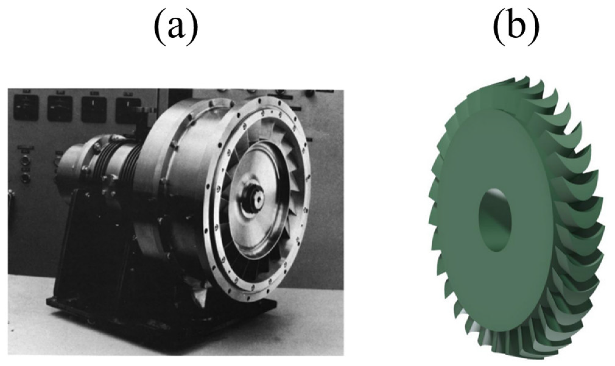
| dynamic expander–compressor | great scalability (1 kWe–500 MWe), high efficiency (~90%), flexible design (multi-stage or multi-unit (train) arrangement) | high investment cost, not adapted for isothermal or two-phase expansion–compression | ✓✓✓ | ✓✓✓ | [132,133,134,135,159,160] |
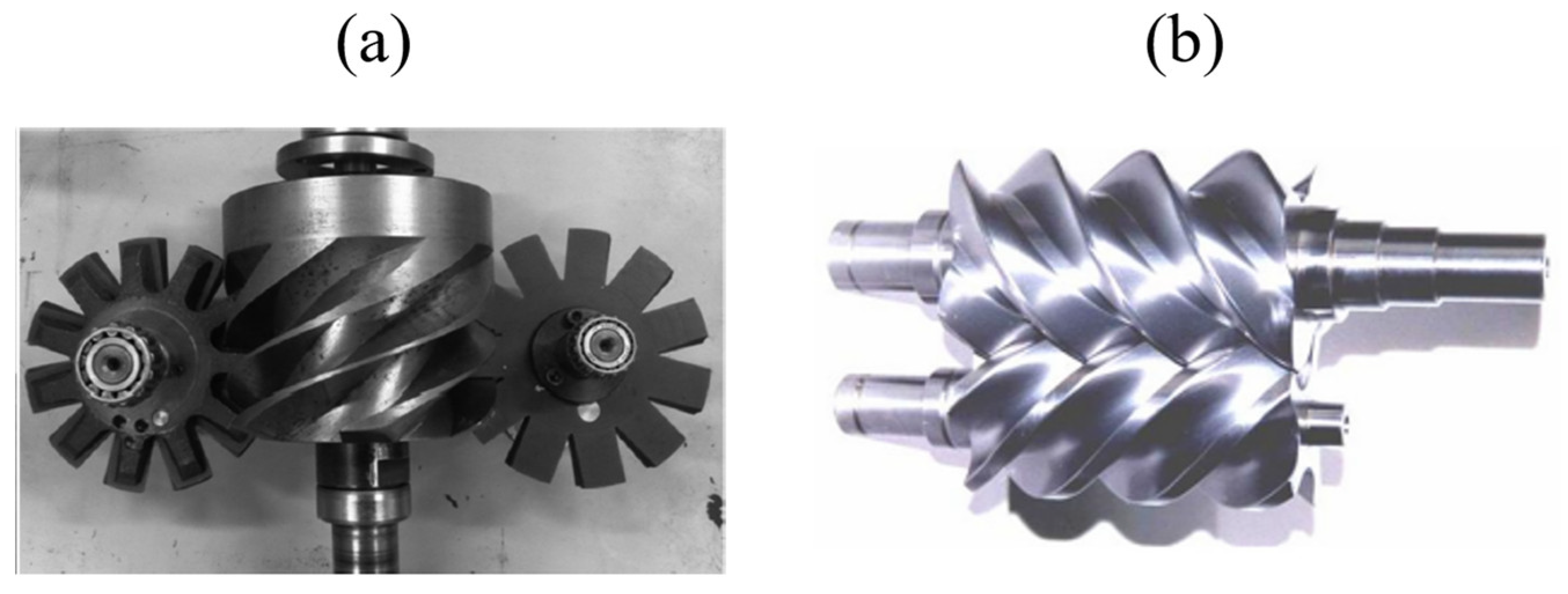
| volumetric expander–compressor | adapted for isothermal or two-phase expansion–compression (I-CAES), a single unit can be operated in both expansion and compression modes, relatively low investment cost | application limited to micro- and small-scale (<1 MWe) CAES systems, lower efficiency than that of dynamic units | adiabatic expansion–compression units—✓ isothermal or two-phase expansion–compression units—✓✓ | adiabatic expansion–compression units—✓✓✓ isothermal or two-phase expansion–compression units—✓ | [131,145,146,155,165,166,167,172,173,174,175] |
| thermal energy storage | increased round-trip efficiency, reduced CO2 emissions | high initial costs, additional space requirements, technical immaturity of systems based on latent heat and thermochemical energy | ✓✓✓ | ✓ | [177] |
| Storage Type | Energy Efficiency [%] | Lifetime [Year or Cycle] | Storage Period [Time] | CAPEX [€/kW] | OPEX [€/kWh] |
|---|---|---|---|---|---|
| Mechanical energy storage | |||||
| Gaseous media (D-CAES) | 40–55 | 20–40 | days | 340–1145 | 0.01–0.26 |
| Gaseous media (A-CAES) | 60–68 | 20–40 | days | 600–800 | n/a |
| Gaseous media (I-CAES) | 95 | 20–40 | days | n/a | n/a |
| Solid media (flywheel) | 85–90 | 10,000–100,000 | hours | 125–275 | 1 |
| Liquid media (PHES) | 65–87 | - | days/months | n/a | n/a |
| Electrical energy storage | |||||
| Supercapacitors | 90–95 | 1 million | seconds/minutes | 125–300 | n/a |
| Superconducting magnets | 90–95 | >1 million | minutes/hours | 300–915 | n/a |
| Electrochemical energy storage | |||||
| Lead-acid batteries | 74–95 | 203–1500 | days/months | 200–490 | 0.16–0.76 |
| Lithium batteries | 90–97 | 3500–20,000 | days/months | 100–200 | 0.13–0.76 |
| Nickel batteries | 71 | 350–2000 | days | 385–1100 | n/a |
| Sodium–sulfur batteries | 75–85 | 2500–8250 | days/months | 285–1075 | 0.07–0.76 |
| Redox flow batteries | 60–80 | 700–15,000 | days/months | 710–1790 | n/a |
| Thermal energy storage | |||||
| Sensible TES | 45–75 | 5000 | days/months | 80–130 | 0.1 |
| Latent TES | 75–90 | 5000 | hours/months | 80–160 | 0.1–0.5 |
| Thermochemical | 80–100 | 5000 | hours/days | n/a | n/a |
| Type of Material/Element for the Air Storage Chamber | Size of the Electrical Storage CAES System [MW] | Cost for the Energy Storage Components [€/kWh] | Typical Storage Time [h] | Total Cost of the CAES Electrical Storage System [€/kW] |
|---|---|---|---|---|
| salt | 200 | 1 | 10 | 340 |
| porous media | 200 | 0.1 | 10 | 330 |
| hard rock | 200 | 29 | 10 | 610 |
| surface piping | 20 | 29 | 3 | 415 |
Disclaimer/Publisher’s Note: The statements, opinions and data contained in all publications are solely those of the individual author(s) and contributor(s) and not of MDPI and/or the editor(s). MDPI and/or the editor(s) disclaim responsibility for any injury to people or property resulting from any ideas, methods, instructions or products referred to in the content. |
© 2024 by the authors. Licensee MDPI, Basel, Switzerland. This article is an open access article distributed under the terms and conditions of the Creative Commons Attribution (CC BY) license (https://creativecommons.org/licenses/by/4.0/).
Share and Cite
Jankowski, M.; Pałac, A.; Sornek, K.; Goryl, W.; Żołądek, M.; Homa, M.; Filipowicz, M. Status and Development Perspectives of the Compressed Air Energy Storage (CAES) Technologies—A Literature Review. Energies 2024, 17, 2064. https://0-doi-org.brum.beds.ac.uk/10.3390/en17092064
Jankowski M, Pałac A, Sornek K, Goryl W, Żołądek M, Homa M, Filipowicz M. Status and Development Perspectives of the Compressed Air Energy Storage (CAES) Technologies—A Literature Review. Energies. 2024; 17(9):2064. https://0-doi-org.brum.beds.ac.uk/10.3390/en17092064
Chicago/Turabian StyleJankowski, Marcin, Anna Pałac, Krzysztof Sornek, Wojciech Goryl, Maciej Żołądek, Maksymilian Homa, and Mariusz Filipowicz. 2024. "Status and Development Perspectives of the Compressed Air Energy Storage (CAES) Technologies—A Literature Review" Energies 17, no. 9: 2064. https://0-doi-org.brum.beds.ac.uk/10.3390/en17092064