
Low-Friction and -Knocking Diesel Engine Cylindrical-Tapered Bore Profile Design
by

Junhong Zhang
1,2,
Ning Wang
1,
Jian Wang
1,3,*,
Hui Wang
1,3,
Xueling Zhang
2,
Huwei Dai
1 and
Jiewei Lin
1,* 1
State Key Laboratory of Engines, Tianjin University, Tianjin 300354, China
2
Department of Mechanical Engineering, Tianjin Renai College, Tianjin 301636, China
3
Weichai Power Co., Ltd., Weifang 261000, China
*
Authors to whom correspondence should be addressed.
Energies 2024, 17(9), 2042; https://0-doi-org.brum.beds.ac.uk/10.3390/en17092042
Submission received: 5 March 2024
/
Revised: 23 April 2024
/
Accepted: 24 April 2024
/
Published: 25 April 2024
(This article belongs to the Topic Zero Carbon Vehicles and Power Generation)
Abstract
:To reduce the friction loss and the piston-knocking noise from the perspective of the design of the cylinder bore profile, the piston-ring cylinder bore (PRCB) dynamic model of an L6 diesel engine was developed using AVL-Excite-Piston & Rings. Based on the full-scale test method, the effects of bore taper, starting height of tapered profile, and ellipticity on the friction power and knocking energy of the PRCB system were investigated, and the optimization of the design of the bore profile was carried out with the objectives of minimizing the system’s friction power and the peak knocking kinetic energy. The results showed that the taper of the cylinder bore has the greatest influence on the system’s friction power and the peak knocking kinetic energy, followed by the starting height of the conical profile. For the peak knocking kinetic energy of the piston, there was an obvious interaction between the taper and the starting height of the conical profile. When the taper was 35 μm and 45 μm, the peak knocking kinetic energy showed a decreasing and then increasing trend with the increase in the starting height of the profile, and when the taper was 55 μm the peak knocking kinetic energy monotonically was decreased with the increase in the starting height of the conical profile. The optimization results showed that the system’s friction power was decreased by 15.05% and the peak knocking kinetic energy was decreased by 21.41% for a taper degree of 55 μm, a tapered profile starting height of 31 mm, and an ellipticity of 50 μm compared to the initial cylindrical cylinder bore.
1. Introduction
With the enhancement of diesel engines, the thermal and mechanical load of their cylinder bore has increased accordingly, and the deformation of the cylinder bore has also increased [1,2,3]. Studies [4,5] have shown that an increase in the degree of irregular cylinder-bore deformation would lead to an increase in friction loss between the piston and cylinder bore. The friction between the piston assembly and cylinder bore accounts for half of the total friction loss of the engine [6,7]. Research has shown that for every 10% increase in engine friction loss, fuel consumption would increase by 3% to 5%, and the engine’s effective output power would also decrease accordingly. The irregular deformation of the cylinder bore will lead to an increase in cylinder clearance, which will cause an increase in piston-knocking noise [8,9]. Therefore, rationalizing the design of the cylinder bore pattern, reducing the friction power and the peak knocking kinetic energy of the PRCB system, is of great significance to improving the economy and NVH performance of diesel engines. Most scholars have chosen to optimize the piston structure [10,11,12] and rationally design the surface texture of the friction pair [13,14,15] to reduce the friction loss and the knocking kinetic energy of the PRCB. Few scholars have improved the friction and lubrication characteristics and knocking characteristics of the PRCB system by rationally designing the macrostructure of the cylinder bore. At present, from the perspective of designing the cylinder bore profile, the use of a non-cylindrical cylinder liner design in the cold state has become another effective method to improve the friction performance of the ring group-cylinder liner system.
The average friction-effective pressure of the piston was reduced [16,17] by expanding the bottom diameter of the cylinder bore of the gasoline engine through the honing process in the experimental test. Numerical calculations were utilized in the literature to compare the deformation of the conical and elliptical cross-section cylinder liner with that of the traditional cylindrical cylinder liner of a certain gasoline engine, and it was found [18,19] that the radial deformation of the elliptical–cone combination cylinder liner was reduced by 70%~80% under the thermal load condition. Alshwawra et al. [20] studied three initial bore shapes of a certain gasoline engine—elliptical, conical–elliptical, and reverse free-form—and found that the reverse free-form bore was closest to a “round” shape at each height after applying thermal and mechanical loads to the bore, and the oil film contact area between the piston ring and the cylinder wall was increased, which provided a new reference for the bore pattern to reduce the friction power of the piston ring group. Halbhuber et al. [21] compared the cumulative friction power of cylindrical bores under the consideration of piston cooling conditions and found that the cumulative friction power of the piston group under cylindrical-tapered compensated bores was 4.4% lower than that using uncompensated bores.
Due to the complexity and high cost of the reverse free-form process, a tapered cylindrical bore is used to improve the geometric performance of the gasoline engine in the cold state, and the tapered bore reduces the friction loss by increasing the distribution of the oil film in the friction gap; however, too large a gap between the piston and the cylinder wall can lead to an increase in the piston-knocking noise, while too small a gap can lead to an increase in the friction power, and the design parameters of the cylinder bore pattern have different degrees of influence on the friction and knocking performance of the piston. Moreover, the design parameters of the cylinder bore pattern have different influences on the piston friction and knocking performance, and there is an interaction between the parameters. At present, there is little literature on the influence of the design parameters of the cylinder bore pattern on the piston friction and knocking characteristics, and there is no systematic design method for the cylinder bore pattern for engineering applications.
Therefore, the influence of the cold design parameters of the cylinder bore pattern on the friction and knocking energy of the piston-ring cylinder bore system in an L6 diesel engine was studied. With the objective function of minimizing the friction power and peak knocking kinetic energy, the parameters of the cylinder bore pattern were optimized, and the optimal design of the cylinder bore pattern was obtained. This provided some theoretical guidance for reducing friction loss and reducing piston-knocking noise from the perspective of cylinder bore design.
2. Numerical Modeling
2.1. The Piston’s Dynamic Modeling
In the motion plane of the diesel engine’s crank-connecting rod mechanism, the forces on the piston are shown in Figure 1, where Frx and Fry are the normal and tangential forces of the piston ring on the piston, respectively, Fcx and Fcy are the normal and tangential forces of the cylinder bore on the piston, respectively, Fp is the force on the piston pin, Frod is the force of the linkage system at the con rod’s small-end bearing, Fgc is the piston gravity, Fgas is the gas force, mc is the mass of the piston, Mgc is the gravity-induced piston moment around the pin axis, Mpc is the friction moment at the piston pin, and β is the crankshaft angle.
After analyzing the force on the piston, the dynamic equations of the piston in the reciprocation, radial motion, and rotation around the pin were expressed as Equations (1)–(3), respectively.
Forces in the x-direction:
Forces in the y-direction:
Rotation around the pin:
where and are the acceleration of the piston motion in the x-direction and y-direction, respectively, and are the component force of piston gravity along the x-direction and y-direction, respectively, and are the load on the piston pin along the x-direction and the force in the y-direction, respectively, and are the force of the linkage system at the con rod’s small-end bearing along the x-direction and the force in the y-direction, respectively, is the piston’s moment of inertia around the pin, is the angular acceleration, Mc is the moment due to piston–liner contact, and is the moment due to ring axial and radial force.
During the working process of the diesel engine, the piston not only reciprocates along the cylinder bore in the height direction, it also includes transverse movement and rotation around the pin, which has a great influence on the piston’s knocking on the inner wall of the cylinder bore to produce knocking noise. Therefore, the piston-knocking kinetic energy was used to measure the degree of piston knocking on the inner wall of the cylinder bore; the specific formula is given as follows:
where Ev and EW are the kinetic energy of radial motion and rotational kinetic energy respectively, mc is the mass of the piston, is the radial velocity, is the rotational moment of inertia, and is the rotational angular velocity.
2.2. The Piston Ring Group Dynamic Model
The force analysis of the piston ring is shown in Figure 2, where mR is the mass of the piston ring, is the acceleration of the piston ring in the x-direction, s is the center of gravity, M is the piston ring cross-section center position, Pabove and Pbelow are the pressure distributions on the upper and lower surfaces of the piston ring, respectively, Pbehind is the pressure distribution on the inside of the piston ring, Ffric,ax is the axial friction between the cylinder bore and piston ring, Fgas,ax is the gas axial force, is the piston ring torsion angle, Fgas,rad is the gas radial force, Ffric,rad is the radial friction between the moving surface of the piston ring and the cylinder bore, and Fhydr,ax and Fhydr,rad are the axial and radial hydrodynamic friction, respectively.
When the ring is floating (the ring is not in contact with the ring groove), the force equilibrium equations between the ring and the ring groove and the dynamic force equilibrium equations can be expressed as follows:
where Fcontact is the contact force between the piston ring and ring groove, Fmass,x is the ring’s gravity force in the axial direction, Fbend is the ring’s bending force; mring is the ring’s mass, is the piston ring’s axial acceleration, Fdamp,ax is the axial damping force, and Ftension is the tangential elasticity of the piston rings.
The piston ring’s radial force equation can be expressed as follows:
The equilibrium equation for the bending moment of the ring section around the form center M is given as follows:
where Fi is the radial and axial forces on the piston rings, hi is the distance from each component force to the center of the piston ring’s cross-section, Mpre-twist is the moment on the piston ring, and Melatic is the bending moment of the piston ring.
2.3. Friction Force Modeling
The state of the oil film between the piston ring group/skirt and the bore liner has an important influence on the dynamics of the PRCB. The pressure distribution of the oil film can be described by the mean Reynolds equation, which is given as follows:
where is the oil film pressure, is the piston movement speed, is the nominal oil film thickness, is the average value of actual oil film thickness, is the combined roughness, is the lubricant power viscosity, and are the pressure flow factors, is the shear flow factor, and is the time.
The calculation assumes that the lubricant film is a Newtonian fluid; the variation in lubricant viscosity with temperature should be described by applying Vogel’s formula:
where A, B, and C are the coefficients of the viscosity equation related to the type of diesel engine, which in this paper take values of 2.4 × 10⁻⁵, 1641, and 170, respectively, and T is the temperature.
During the reciprocating motion of the piston, the oil film’s thickness and pressure are in a state of dynamic change. When the piston moment reaches a certain level, the thickness of the oil film decreases rapidly, which leads to the direct contact of the piston skirt or the piston ring with the micro-convexity on the cylinder bore’s surface, and the normal pressure of the contact surface at this time is determined by the contact model of the micro-convexity of the GREENWOOD.
The ratio of the friction pair to the combined roughness of the friction pair is defined as the minimum film thickness ratio, which is calculated as follows:
where hmin is the minimum film thickness, Hmin is the minimum film thickness ratio, and σ is the combined roughness. An Hmin value of less than 1 indicates boundary lubrication, and Hmin value of 1 to 4 indicates mixed lubrication, and an Hmin value greater than 4 indicates hydrodynamic lubrication.
The friction between the piston ring group and the inner wall of the cylinder bore can be derived from Stribeck’s formula:
where Fn is the force of pressure between the piston/piston ring and the inner wall of the cylinder bore, and μ is the coefficient of friction.
where is the overall scaling factor; A, B, C, and D are related to the form of the diesel engine; and v is the dynamic viscosity coefficient.
2.4. Cylinder Bore Deformation Calculation
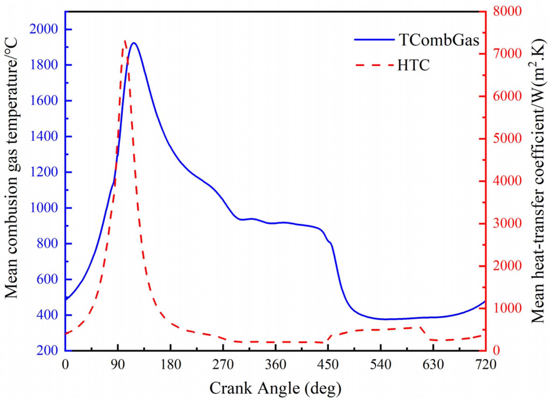
Firstly, one-dimensional simulation on the working process of an inline six-cylinder diesel engine was carried out by AVL BOOST [22], and the main parameters of the engine were as shown in Table 1. The thermal boundary conditions, such as gas temperature and convective heat transfer coefficient, were obtained from one-dimensional simulations, as shown in Figure 3, which shows the variation in the convective heat transfer coefficient and temperature in the combustion chamber with the crankshaft angle, and it can be seen that both of them reach their maximum value near the upper stop (90CA), due to the huge heat generated by the gas explosion in the cylinder at this time.
In the actual working process of the diesel engine, due to the thermal inertia of the body material, the effect of the heat load of the high-temperature gas on the body is limited to a thin layer on the surface of the material. The temperature of the vast majority of the region is approximate to stabilize; that is, the wall surface of the combustion chamber can be formed without a time-varying steady-state temperature field [23].
The time-averaged convective heat transfer coefficient and temperature of the gas were applied to the finite element model in the form of a third-type boundary condition. In the simulation process, the deformation of the cylinder bore is mainly determined by the inhomogeneous thermal load, and since it is assumed that the thermal load is steady-state and the fuel of each cylinder is consistent in the calculation process, the radial deformation of each cylinder due only to the thermal load is roughly the same, but the deformation of cylinders 2, 3, and 4 is affected by the adjacent two cylinders at the same time, while cylinders 1 and 6 are affected by only one of the neighboring cylinders; thus, in a comprehensive view, the deformation of cylinders 1 and 6 is symmetrically similar, while the deformation of cylinders 2, 3, and 4 is similar, so the calculation process can be simplified to cylinders 1, 2, and 6 in order to ensure the accuracy of the premise, greatly reducing the computing time. The deformation of the engine body was calculated in ABAQUS, and the whole deformation of the engine was as shown in Figure 4. The radial deformation of the bore surface of cylinder 2 was also extracted as a boundary condition for the subsequent dynamic calculations.
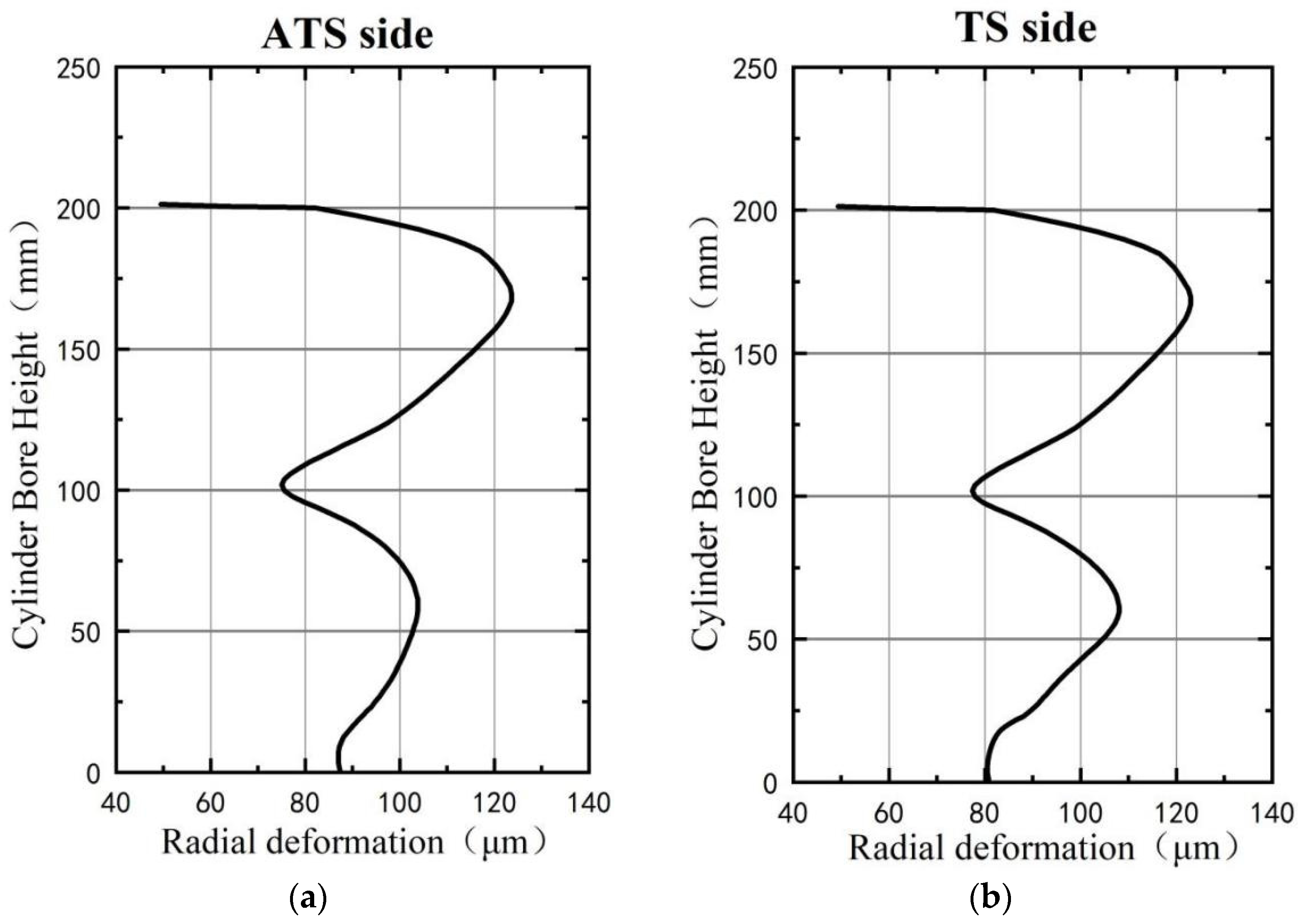
Figure 5 shows the radial deformation of the cross-section of the inner wall at different heights in the thermal state of the cylindrical cylinder bore. Since the 0° anti-thrust side (ATS) and 180° thrust side (TS) were subjected to thermal loads in addition to piston-knocking loads, the deformation in the 0° and 180° directions was larger than that in the 90° and 270° directions at different heights, and the overall deformation showed an “oval shape”. Figure 6 shows the radial deformation of the cylinder bore surface on the ATS and TS. Due to the influence of the bolt preload, the deformation at the top of the cylinder bore is small, and the deformation on the ATS and TS is 49.35 μm and 49.45 μm, respectively. Due to the large thermal load on the top half of the cylinder bore, the middle and upper portion of the cylinder bore show more prominent expansion deformation, and the maximum deformation occurs on the TS, with an amplitude of 122.93 μm; the lower part of the cylinder bore shows a smaller expansion deformation relative to the upper part, and the maximum deformation occurs on the TS, with an amplitude of 108.04 μm.
2.5. The Piston-Ring Cylinder Bore (PRCB) Dynamic Model
The working condition of the engine is complicated; many factors can affect the normal operation of piston friction pairs. The dynamic model of the piston-ring cylinder bore was established by AVL Piston & Rings software R2020.1 [24], which can fully account for the lubrication of the piston group. The modeling process included the following assumptions: (1) Only the motion of the piston in the plane of the TS and ATS was considered. (2) The crankshaft speed was even. (3) The piston was considered to be an elastic body; the cylinder liner, connecting rod, and crankshaft were defined as rigid bodies; and the hinge clearance was zero.
In the modeling process, the cylinder bore deformation profile obtained from the cylinder bore deformation calculation was input as the geometric boundary condition of the calculation.
2.6. Dynamic Model Calibration
The piston leakage is directly affected by the structure of the piston ring group and the deformation of the cylinder bore’s inner wall. The accuracy of the PRCB dynamic model established in the previous section was verified by comparing the piston leakage results in the numerical model with that in the experiment. The test process was as follows: block all channels of crankcase interaction with the outside world; keep the crankcase sealing normal (add 0.2 kPa pressure in the crankcase; the amount of air leakage is no more than 5 L/min), after which the throttle is fully open; adjust the engine speed from 1300 r/min to 2100 r/min and record the average leakage of air at each speed point in the process. Figure 7 shows the comparison of the average leakage of a single cylinder in a cycle of the diesel engine (the ratio of total air leakage of the diesel engine to the number of cylinders) in the experiment and the numerical model. It can be seen that the measured and simulated values of piston air leakage under each rotational speed were of the same order of magnitude, and the maximum error was 5.52%, verifying the accuracy of the PRCB dynamic model.
2.7. Design of Cylinder Bore Profiles
A comprehensive experimental method was used to study the influence of the bore pattern parameters on the friction and knocking characteristics of the piston, and the optimal design of the bore pattern was derived to minimize the friction power of the PRCB system and minimize the peak knocking kinetic energy.
A combination of cylindrical taper and elliptical cross-section was adopted for the cylinder bore’s cold-state profile, as shown in Figure 8, where A is the taper, and the friction power between the piston and bore was reduced through the optimization of the taper; B is the starting height of the conical profile, and the second-order movement of the piston was improved through the optimization of B; C is the degree of ellipticity, and the ellipse of the difference between the long and short axes of half of the difference between the C is a positive number indicating the different heights that can be attenuated under the cylinder bore’s radial deformation to reduce the friction power; and L is the cylinder bore diameter. Subsequent calculations directly superimposed the cold and hot profiles of the cylinder bore as boundary conditions for the dynamic calculations.
3. Effect of Cylindrical-Tapered Cylinder Bore Shape Parameters on Friction and Knocking
The control variable method was used to analyze the effects of A, B, and C on the piston friction and knocking characteristics, where the piston friction characteristics were evaluated by the average friction power consumption per cycle, and the knocking characteristics were evaluated by the peak kinetic energy of the piston knocking per cycle.
The effects of the cylindrical-tapered bore profile parameters taper (A), tapered profile start height (B), and ellipticity (C) on the piston skirt friction consumption, piston ring friction consumption, and peak knocking kinetic energy are shown in Figure 9. Overall, the cylindrical-tapered bore has improved friction and knocking characteristics compared to the cylindrical bore.
As shown in Figure 9a, at B = 62 mm, C = 40 μm, and peak kinetic energy was decreased with the increase in taper (A); the skirt friction power was decreased from 232 J to 216 J, the ring group friction power was decreased from 77.87 J to 69.32 J, and the peak kinetic energy was decreased from 256.12 N·mm to 191.97 N·mm. Among them, the rate of decrease in skirt friction power was from fast to slow, while the speed of the decrease in ring group friction power and peak knocking kinetic energy tended to be constant. All three decreased because with the increase in taper (A), the thickness of the oil film between the piston ring’s moving surface bore wall and the piston skirt bore wall increases, the area of solid–solid contact between the friction partners decreases, and the dry friction decreases, so the skirt’s friction work and the piston ring’s friction work are both reduced. At the same time, with the increase in oil film thickness, the viscous shear force of the oil film also increases, and the rotation speed of the piston’s knocking moment is reduced, so the peak kinetic energy of the piston knocking is reduced.
As shown in Figure 9b, when B was increased at A = 45 μm and C = 40 μm, the piston skirt friction power and ring set friction power increased from 215 J to 225 J and from 70.15 J to 74.54 J, respectively. The peak piston-knocking kinetic energy decreased and then increased with the increase in B, with a minimum value of 202.79 N at B = 41 mm. The reason for the change in these three parameters is that with the increase in the starting height (B) of the profile, the range of tapered compensation along the height gradually decreases, so the piston skirt and the piston ring moving surface and the cylinder wall in the piston are gradually reduced within a cycle of the average clearance, resulting in a gradual decrease in the average thickness of the lubricant film, and the friction in the solid–solid contact area increases, resulting in an increase in dry friction, so the skirt friction and the friction of the piston ring work increase. The peak knocking kinetic energy is determined by the piston’s radial speed and rotation speed. The reduction in the skirt’s oil film thickness makes the oil film pressure increase, and the piston’s radial speed is weakened, the oil film’s viscous shear force decreases, and the piston’s angular speed increases, but the piston’s radial speed decreases significantly, so the peak knocking kinetic energy as B changes from 0 to 41 mm follows a downward trend, and then as B continues to increase, the angular velocity of the piston’s rotation increases more than the radial velocity decreases, so the peak knocking kinetic energy shows an upward trend.
As shown in Figure 9c, at A = 45 μm and B = 62 mm, with the increase in C, both the friction power of the piston skirt and the peak knocking kinetic energy show a decreasing and then increasing trend, achieving minimum values of 216.74 J and 230.27 N·mm at C = 40 μm. The friction power of the piston ring group shows a decreasing trend from 76.25 J to 71.11 J with the increase in C. The reasons for these changes in the three parameters are as follows: with the increase in ellipticity (C), the second-order deformation amplitude of the cylinder bore is gradually weakened, and each cross-section of different heights of the cylinder bore is closer to the “round”, while the lubricating oil film around the piston skirt and the piston ring is more uniformly distributed, so the friction power consumption of the piston skirt and the friction power consumption of the piston ring group are gradually reduced. At the same time, because of the increase in ellipticity (C), the gap between the TS and ATS of the piston skirt does not change significantly, so the peak value of knocking kinetic energy does not change significantly.
3.1. Factorial Analysis
The cold-profile parameter factor levels for the cylinder bore under the full-scale test are shown in Table 2. Three parameters related to the design of the cylinder bore’s cold profile—namely, taper (A), starting height of tapered profile (B), and ellipticity (C)—were selected as the test factors, and three levels were taken for each factor. The level sizes were selected based on the results of the previous calculations.
The test scheme and calculation results are shown in Table 3. The effects of the three parameters (A, B, and C) on the piston skirt friction power, the piston ring group friction power, the total friction power (the sum of the ring group friction power and the skirt friction power), and the peak knocking kinetic energy were investigated, where Ai, Bi, and Ci denote the taper, starting height of the tapered profile, and ellipticity at their corresponding ith-level values, respectively.
3.2. Analysis of Results
The data obtained from the calculations were analyzed using the range method, and the range results reflected the influence degree of each factor on the calculation results. The factor with the largest range has the highest influence on the results and is the main factor. Range is defined as follows:
where is equal to the sum of certain indicators of level i in the sum column of Table 3, is the arithmetic mean of Ki, and s is the number of factor levels.
The influencing factors are taper (A), taper start height (B), ellipticity (C), and the interaction between the three (A × B, A × C, B × C,), and the calculated indices are the skirt friction power, the piston ring group friction power, the total friction power (the sum of the friction power of the skirt and the friction power of the ring group), and the peak of the kinetic energy of the piston knocking. Table 4 and Table 5 show the range method tables.
3.2.1. Effect of Taper (A) with Respect to Different Values of Ellipticity (C)
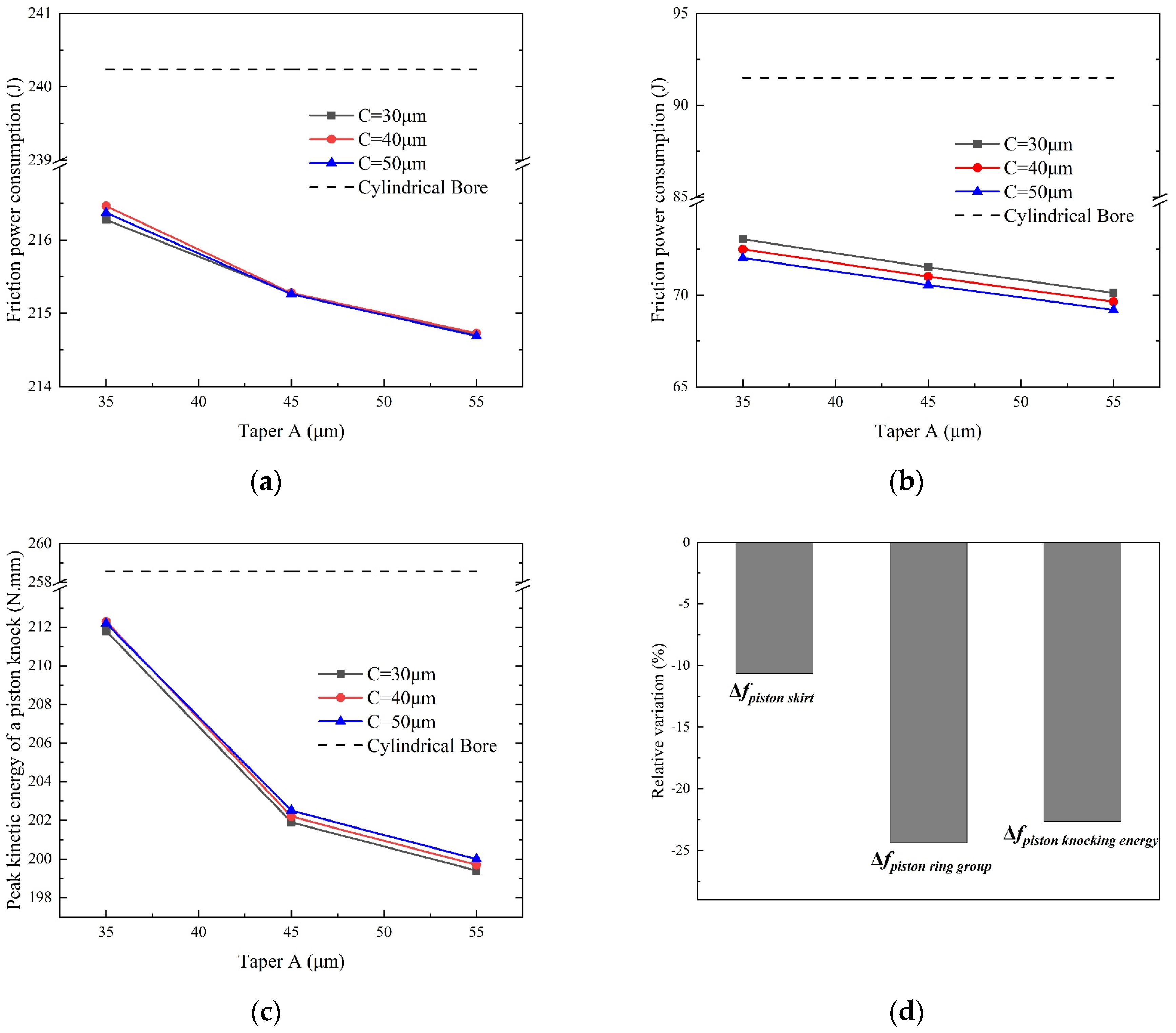
The influence of taper (A) on the friction and knocking characteristics under different values of ellipticity (C) is shown in Figure 10. The starting height of the conical profile (B) remained unchanged at 41 mm, the taper (A) was varied from 35 μm to 55 μm, and different colors indicate different values of ellipticity (C). The dotted lines in Figure 10 represent the values corresponding to the cylindrical cylinder bores (not to be repeated later). For all of the values of C studied in this work, the friction power of the skirt and the ring group, along with the peak knocking kinetic energy, decreased with the increase in A. The optimal parameter set was obtained as A = 55 μm, C = 50 μm, and B = 41 mm; as shown in Figure 10d, under this parameter set, compared to cylindrical cylinder bores, the friction power of the skirt was reduced by 10.63%, the friction power of the ring group was reduced by 24.38%, and the peak knocking kinetic energy was reduced by 22.64%.
3.2.2. Effect of Starting Height of Tapered Profile (B) with Respect to Different Values of Ellipticity (C)
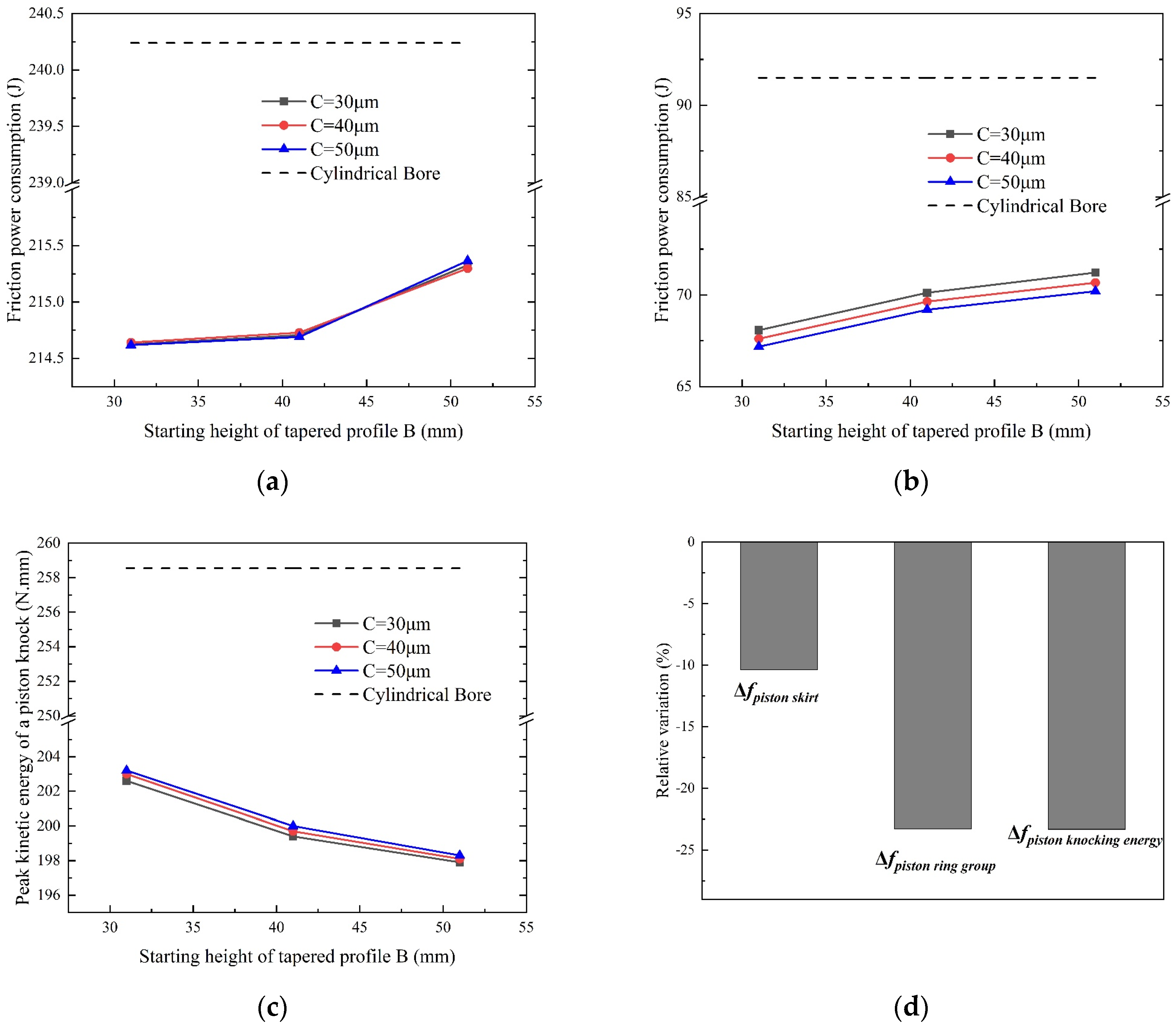
Figure 11 shows the influence of the starting height of the conical profile (B) on the friction and knocking characteristics under different values of ellipticity (C). The taper (A) was kept unchanged at 55 μm, and the starting height of the conical profile (B) was varied from 31 mm to 51 mm. The friction power of the skirt and ring group increased with B regardless of the C value, and the peak knocking kinetic energy decreased with the increase in B. The optimal parameter set was obtained as A = 55 μm and C = 50 μm, and the peak knocking kinetic energy decreased with the increase in B. The optimal parameter set was obtained as A = 55 μm, C = 50 μm, and B = 31 mm; as shown in Figure 11d, under this parameter set, compared to cylindrical cylinder bores, the skirt friction power was reduced by 10.35%, the ring group friction power was reduced by 23.28%, and the peak knocking kinetic energy was reduced by 23.30%.
3.2.3. Effect of Starting Height of Tapered Profile (B) with Respect to Different Values of Taper (A)
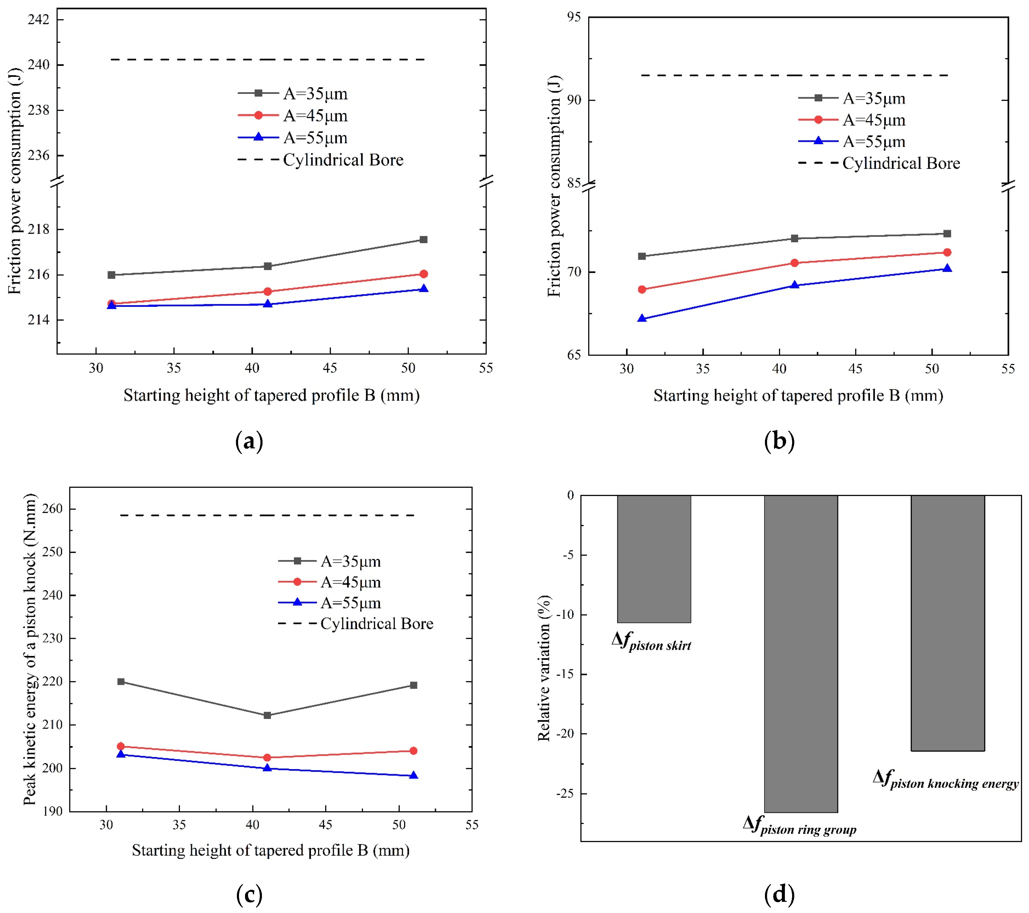
The influence of the starting height of the conical profile (B) on the friction characteristics and knocking characteristics under different values of taper (A) is shown in Figure 12. The ellipticity (C) remained unchanged at 50 μm, and the starting height of the tapered profile (B) was varied from 31 μm to 51 μm. The friction power of the skirt and the ring group increased with B regardless of the value of A. However, this growth rate was decreased with increasing B. For the peak knocking kinetic energy, there was an interaction between A and B. When A was taken as 35 μm and 45 μm, the peak piston-knocking kinetic energy showed a decreasing and then increasing trend with the increase in B. When the taper (A) was 55 μm, the peak piston-knocking kinetic energy monotonically decreased with the increase in B. The optimal parameter set was taken as A = 55 μm, C = 50 μm, and B = 31 mm. As shown in Figure 12d, under this parameter set, compared to cylindrical cylinder bores, the friction power of the skirt was reduced by 10.66%, the friction power of the ring group was reduced by 26.59%, and the peak knocking kinetic energy was reduced by 21.41%.
3.3. Comparison between Optimal and Baseline Design
Compared with the peak kinetic energy of the piston knocking, taking the friction consumption of the piston system as the main consideration, A = 55 μm, B = 31 mm, and C = 50 μm were selected as the optimized cylinder bore profile parameter combination; the variation in friction characteristics and knocking characteristics with the crankshaft rotation angle for the cylindrical bore and optimized cylindrical-tapered bore is shown in Figure 13.
After profile parameter optimization, the total friction power of the piston group was reduced by 49.95 J, which mean a decrement of 15.05%. The decrement of friction power was beneficial for reduced fuel consumption. The peak piston knock kinetic energy was reduced by 55.35 N·mm, representing a decrement of 21.41%. The reduction in knocking kinetic energy can reduce the risk of engine cavitation and improve engine NVH performance.
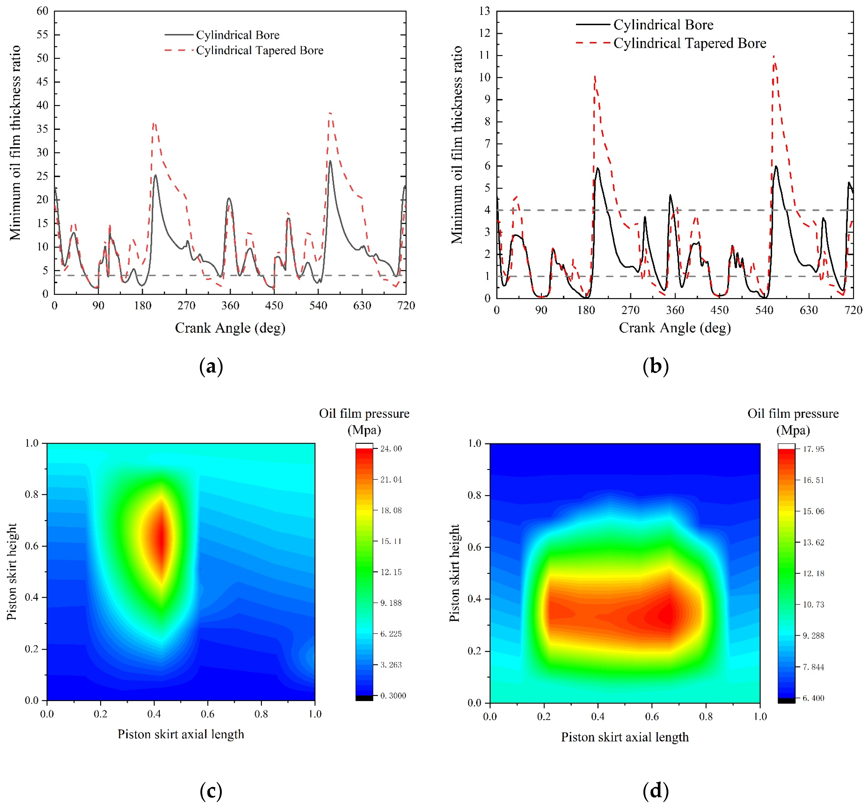
Figure 14 shows the comparison of the minimum film thickness ratio and film pressure on the friction pair. Only the minimum film thickness ratio of the first is shown in Figure 14b, since the first compressor ring accounts for the majority of the friction power in the ring group. Compared with that in the cylindrical bore, the minimum film thickness ratio between the piston skirt and the piston ring moving surface of the cylindrical-tapered bore was improved, as shown in Figure 14a, so the latter resulted in a smaller friction power. The distribution of the oil film pressure on the skirt at the moment of piston knocking is shown in Figure 14c,d. The peak oil film pressure was smaller in the cylindrical-tapered bore and the area of the oil-film-bearing area was larger, which effectively absorbed the kinetic energy of the piston’s second-order motion, so the peak knocking kinetic energy was reduced in the latter case.
4. Conclusions
- (1)
- The taper has the greatest effect on the total friction power and the peak piston-knocking kinetic energy, followed by the starting height of the conical profile, while the ellipticity has the smallest effect; for the peak piston-knocking kinetic energy, there was a significant interaction between the taper and the starting height of the conical profile.
- (2)
- Compared with the cylindrical bore, the optimized skirt friction work of the cylindrical-tapered bore decreased from 240.24 J to 214.62 J, with a decrease of 10.66%; the piston ring friction work decreased from 91.5 J to 67.17 J, with a decrease of 26.59%; and the peak knocking kinetic energy decreased from 258.55 N·mm to 203.2 N·mm, with a decrease of 21.41%.
- (3)
- Compared with the cylindrical bore, the minimum oil film thickness on the moving surface of the piston skirt and the piston ring was increased in the cylindrical-tapered bore, which reduced the contact time of dry friction and increased the contact time of hydrodynamic friction at the piston-knocking moment. The cylindrical-tapered bore provided a larger contact area and oil film thickness, which absorbed some of the energy of the second-order motion of the piston and attenuated the impact.
Author Contributions
Conceptualization, H.D. and N.W.; methodology, J.L.; software, N.W.; validation, N.W., J.W. and X.Z.; formal analysis, N.W.; investigation, H.W.; resources, J.W.; data curation, H.W.; writing—original draft preparation, N.W.; writing—review and editing, H.D.; visualization, X.Z.; supervision, J.L.; project administration, J.Z.; funding acquisition, J.Z. All authors have read and agreed to the published version of the manuscript.
Funding
This research was funded by the National Natural Science Foundation of China (Grant No. 52205166).
Data Availability Statement
The original contributions presented in the study are included in the article, further inquiries can be directed to the corresponding authors.
Conflicts of Interest
Authors Jian Wang and Hui Wang were employed by the Weichai Power Co., Ltd. The remaining authors declare that the research was conducted in the absence of any commercial or financial relationships that could be construed as a potential conflict of interest.
References
- Bi, Y.; Wang, P.; Luo, L.; Wang, H.; Xin, Q.; Lei, J.; Shen, L. Analysis of out-of-round deformation of a dry cylinder liner of a non-road high-pressure common-rail diesel engine based on multi-field coupling. J. Braz. Soc. Mech. Sci. 2021, 43, 50. [Google Scholar] [CrossRef]
- Bi, Y.; Wang, P.; Xiang, R.; Wen, J.; Lei, J.; Shen, L.; Xin, Q. Numerical investigation on the operating characteristics of the cylinder liners of a turbocharged diesel engine. Sādhanā 2021, 46, 150. [Google Scholar] [CrossRef]
- Li, G.; Gu, F.; Wang, T.; Lu, X.; Zhang, R.; Ball, A. A dynamic deformation based lubrication model between the piston rings and cylinder liner. In Proceedings of the 2017 23rd International Conference on Automation and Computing (ICAC), Huddersfield, UK, 7–8 September 2017; pp. 1–6. [Google Scholar] [CrossRef]
- Delprete, C.; Razavykia, A. Piston dynamics, lubrication and tribological performance evaluation: A review. Int. J. Engine Res. 2020, 21, 725–741. [Google Scholar] [CrossRef]
- Sato, K.; Fujii, K.; Ito, M.; Koda, S. Application to Engine Development of Friction Analysis by Piston Secondary Motion Simulation in Consideration of Cylinder Block Bore Distortion; 0148-7191; Technical Paper; SAE: Washington, DC, USA, 2006. [Google Scholar] [CrossRef]
- Styles, G.; Rahmani, R.; Rahnejat, H.; Fitzsimons, B. In-cycle and life-time friction transience in piston ring–liner conjunction under mixed regime of lubrication. Int. J. Engine Res. 2014, 15, 862–876. [Google Scholar] [CrossRef]
- Wang, Y.; Ma, X.; Li, T.; Lu, X.; Li, W. Influence of thermal effect in piston skirt lubrication considering thermal deformation of piston and cylinder liner. Int. J. Engine Res. 2023, 24, 14680874231155571. [Google Scholar] [CrossRef]
- Li, G.; Gu, F.; Wang, T.; Lu, X.; Zhang, L.; Zhang, C.; Ball, A. An improved lubrication model between piston rings and cylinder liners with consideration of liner dynamic deformations. Energies 2017, 10, 2122. [Google Scholar] [CrossRef]
- Lu, Y.; Li, S.; Wang, P.; Liu, C.; Zhang, Y.; Müller, N. The analysis of secondary motion and lubrication performance of piston considering the piston skirt profile. Shock. Vib. 2018, 2018, 3240469. [Google Scholar] [CrossRef]
- Zhang, J.; Piao, Z.; Liu, S. Influence of skirt profile structure of gasoline engine piston on the friction and wear characteristics under standard conditions. J. Tribol. 2018, 140, 021703. [Google Scholar] [CrossRef]
- Totaro, P.P.; Westerfield, Z.; Tian, T. Introducing a New Piston Skirt Profile to Reduce Engine Friction; 0148-7191; Technical Paper; SAE: Washington, DC, USA, 2016. [Google Scholar] [CrossRef]
- Pawlus, P.; Reizer, R. Functional importance of honed cylinder liner surface texture: A review. Tribol. Int. 2022, 167, 107409. [Google Scholar] [CrossRef]
- Guo, Z.; Yuan, C.; Liu, P.; Peng, Z.; Yan, X. Study on influence of cylinder liner surface texture on lubrication performance for cylinder liner–piston ring components. Tribol. Lett. 2013, 51, 9–23. [Google Scholar] [CrossRef]
- Grabon, W.; Pawlus, P.; Wos, S.; Koszela, W.; Wieczorowski, M. Evolutions of cylinder liner surface texture and tribological performance of piston ring-liner assembly. Tribol. Int. 2018, 127, 545–556. [Google Scholar] [CrossRef]
- Mezghani, S.; Demirci, I.; Yousfi, M.; El Mansori, M. Mutual influence of crosshatch angle and superficial roughness of honed surfaces on friction in ring-pack tribo-system. Tribol. Int. 2013, 66, 54–59. [Google Scholar] [CrossRef]
- Hu, Y.; Meng, X.; Xie, Y.; Fan, J. Mutual influence of plateau roughness and groove texture of honed surface on frictional performance of piston ring–liner system. Proc. Inst. Mech. Eng. Part J. J. Eng. Tribol. 2017, 231, 838–859. [Google Scholar] [CrossRef]
- Edtmayer, J.; Lösch, S.; Hick, H.; Walch, S. Comparative study on the friction behaviour of piston/bore interface technologies. Automot. Engine Technol. 2019, 4, 101–109. [Google Scholar] [CrossRef]
- Alshwawra, A.; Pohlmann-Tasche, F.; Stelljes, F.; Dinkelacker, F. Enhancing the Geometrical Performance Using Initially Conical Cylinder Liner in Internal Combustion Engines—A Numerical Study. Appl. Sci. 2020, 10, 3705. [Google Scholar] [CrossRef]
- Alshwawra, A.; Pasligh, H.; Hansen, H.; Dinkelacker, F. Increasing the roundness of deformed cylinder liner in internal combustion engines by using a non-circular liner profile. Int. J. Engine Res. 2021, 22, 1214–1221. [Google Scholar] [CrossRef]
- Alshwawra, A.; Pohlmann-Tasche, F.; Stelljes, F.; Dinkelacker, F. Effect of freeform honing on the geometrical performance of the cylinder liner—Numerical study. SAE Int. J. Engines 2022, 16, 463–486. [Google Scholar] [CrossRef]
- Halbhuber, J.; Wachtmeister, G. Effect of Form Honing on Piston Assembly Friction; 0148-7191; Technical Paper; SAE: Washington, DC, USA, 2020. [Google Scholar] [CrossRef]
- AVL LIST GmbH. BOOST Rev 2017.1 Users Guide; AVL LIST GmbH: Steiermark, Austria, 2017. [Google Scholar]
- Liang, X.; Wang, Y.; Huang, S.; Yang, G.; Tang, L.; Cui, G. Investigation on Cylinder Bore Deformation under Static Condition Based on Fourier Decomposition; 0148-7191; Technical Paper; SAE: Washington, DC, USA, 2017. [Google Scholar] [CrossRef]
- AVL LIST GmbH. Excite Piston & Rings Rev 2017.1 Users Guide; LIST GmbH: Steiermark, Austria, 2017. [Google Scholar]
Figure 1.
Schematic diagram of piston movement force analysis under calibration conditions.

Figure 2.
Schematic diagram of piston ring force under calibration conditions.

Figure 3.
Gas temperature and convective heat transfer coefficient.

Figure 4.
Schematic diagram of cylinder bore deformation.

Figure 5.
Radial deformation at different heights of the cylinder bore.

Figure 6.
Radial deformation of the ATS and TS: (a) ATS radial deformation; (b) TS radial deformation.
Figure 6.
Radial deformation of the ATS and TS: (a) ATS radial deformation; (b) TS radial deformation.

Figure 7.
Comparison between measured and simulated average air leakage of a single piston cylinder.
Figure 7.
Comparison between measured and simulated average air leakage of a single piston cylinder.

Figure 8.
Cold profile of cylinder bore: (a) front cutaway view; (b) top view.

Figure 9.
Cylinder bore profile parameters’ effects on the piston friction lubrication characteristics and knocking characteristics by (a) taper (B = 62 mm, C = 40 μm); (b) starting height of tapered profile (A = 45 μm, C = 40 μm); and (c) ellipticity (A = 45 μm, B = 62 mm).
Figure 9.
Cylinder bore profile parameters’ effects on the piston friction lubrication characteristics and knocking characteristics by (a) taper (B = 62 mm, C = 40 μm); (b) starting height of tapered profile (A = 45 μm, C = 40 μm); and (c) ellipticity (A = 45 μm, B = 62 mm).

Figure 10.
Effect of taper (A) on the piston friction lubrication characteristics and knocking characteristics with different values of ellipticity (C): (a) piston skirt friction power; (b) piston ring group friction power; (c) peak kinetic energy of piston knocking; (d) relative changes brought by the optimal parameter group (A = 55 mm, C = 50 μm, B = 41 mm).

Figure 11.
Effect of starting height of tapered profile (B) on the piston friction lubrication characteristics and knocking characteristics with different values of ellipticity (C): (a) piston skirt friction power; (b) piston ring group friction power; (c) peak kinetic energy of piston knocking; (d) relative changes brought by the optimal parameter group (B = 31 mm, C = 50 μm, A = 55 μm).

Figure 12.
Effect of starting height of tapered profile (B) on the piston friction lubrication characteristics and knocking characteristics with different values of taper (A): (a) piston skirt friction power; (b) piston ring group friction power; (c) peak kinetic energy of piston knocking; (d) relative changes brought by the optimal parameter group (A = 55 μm, B = 31 mm, C = 50 μm).

Figure 13.
Comparison of piston friction characteristics and knocking characteristics before and after optimization: (a) skirt friction power change; (b) ring group friction power change; (c) total friction power change; (d) knocking kinetic energy change.
Figure 13.
Comparison of piston friction characteristics and knocking characteristics before and after optimization: (a) skirt friction power change; (b) ring group friction power change; (c) total friction power change; (d) knocking kinetic energy change.

Figure 14.
Comparison of oil film thickness and oil film pressure distribution in the cylinder bore before and after optimization: (a) minimum oil film thickness ratio change in the skirt; (b) minimum oil film thickness ratio change for the 1st ring; (c) oil film pressure distribution in the skirt at the moment of piston knocking (pre-optimization); (d) oil film pressure distribution in the skirt at the moment of piston knocking (post-optimization).


Table 1.
Main engine parameters.
| Parameters | Value |
|---|---|
| Maximum power | 235 kW |
| Maximum moment | 1300 N·m |
| Number of cylinders | 6 |
| Diameter of a cylinder | 107 mm |
| Stroke | 126 mm |
| Engine capacity | 6.8 L |
| Compression ratio | 19.5 |
Table 2.
Factor level values of type line parameters under the full-scale test.
| Level | A/μm | B/mm | C/μm |
|---|---|---|---|
| 1 | 35 | 31 | 30 |
| 2 | 45 | 41 | 40 |
| 3 | 55 | 51 | 50 |
Table 3.
Full-scale test scenarios and calculations.
| Programmatic | Skirt Friction Power/J | Ring Group Friction Power/J | Total FrictionPower/J | Peak Knocking Kinetic Energy/(N·mm) |
|---|---|---|---|---|
| A1B1C1 | 215.62 | 71.86 | 287.48 | 219 |
| A1B1C2 | 215.62 | 71.36 | 286.98 | 220 |
| A1B1C3 | 215.79 | 70.89 | 286.68 | 220 |
| A1B2C1 | 216.09 | 72.98 | 289.04 | 212 |
| A1B2C2 | 216.26 | 72.42 | 288.69 | 212 |
| A1B2C3 | 216.18 | 71.95 | 288.13 | 212 |
| A1B3C1 | 217.53 | 73.37 | 290.90 | 219 |
| A1B3C2 | 217.42 | 72.75 | 290.19 | 219 |
| A1B3C3 | 217.36 | 72.25 | 289.60 | 219 |
| A2B1C1 | 214.61 | 69.83 | 284.41 | 205 |
| A2B1C2 | 214.58 | 69.33 | 283.91 | 205 |
| A2B1C3 | 214.52 | 68.88 | 283.41 | 205 |
| A2B2C1 | 215.08 | 71.45 | 286.53 | 202 |
| A2B2C2 | 215.08 | 70.95 | 286.03 | 202 |
| A2B2C3 | 215.06 | 70.48 | 285.56 | 203 |
| A2B3C1 | 215.85 | 72.19 | 288.04 | 204 |
| A2B3C2 | 215.88 | 71.63 | 287.48 | 204 |
| A2B3C3 | 215.85 | 71.12 | 286.98 | 204 |
| A3B1C1 | 214.44 | 68.00 | 282.43 | 203 |
| A3B1C2 | 214.44 | 67.56 | 281.99 | 203 |
| A3B1C3 | 214.41 | 67.11 | 281.55 | 203 |
| A3B2C1 | 214.49 | 70.06 | 284.56 | 199 |
| A3B2C2 | 214.52 | 69.56 | 284.11 | 200 |
| A3B2C3 | 214.49 | 69.12 | 283.61 | 200 |
| A3B3C1 | 215.11 | 71.15 | 286.30 | 198 |
| A3B3C2 | 215.08 | 70.59 | 285.71 | 198 |
| A3B3C3 | 215.17 | 70.12 | 285.29 | 198 |
Table 4.
Range method of friction characteristics due to a single parameter.
| Parameter Factor Level | Skirt Friction Power/J | Range | Piston Ring Group Friction Power/J | Range | Total Friction Power/J | Range | Peak Knocking Kinetic Energy/N·mm | Range |
|---|---|---|---|---|---|---|---|---|
| A1 | 216.41 | 1.71 | 72.22 | 3.30 | 288.628 | 4.69 | 217 | 16 |
| A2 | 215.17 | 70.65 | 285.8255 | 203 | ||||
| A3 | 214.70 | 68.91 | 283.9375 | 200 | ||||
| B1 | 214.88 | 1.27 | 69.41 | 2.27 | 284.321 | 3.51 | 209 | 4 |
| B2 | 215.26 | 71.01 | 286.2385 | 204 | ||||
| B3 | 216.15 | 71.69 | 287.8315 | 207 | ||||
| C1 | 215.41 | 0.02 | 71.21 | 1.00 | 286.622 | 0.97 | 206 | 1 |
| C2 | 215.44 | 70.68 | 286.1205 | 207 | ||||
| C3 | 215.41 | 70.21 | 285.6485 | 207 |
Table 5.
Range method of friction characteristics due to interactions between profile parameters.
| Norm | Interactions | Range |
|---|---|---|
| Skirt friction power | A × B | 0.56 |
| A × C | 0.03 | |
| B × C | 0.06 | |
| Piston ring friction power | A × B | 0.86 |
| A × C | 0.06 | |
| B × C | 0.09 | |
| Total friction power | A × B | 0.38 |
| A × C | 0.06 | |
| B × C | 0.12 | |
| Peak knocking kinetic energy (physics) | A × B | 11.80 |
| A × C | 2.95 | |
| B × C | 2.95 |
Disclaimer/Publisher’s Note: The statements, opinions and data contained in all publications are solely those of the individual author(s) and contributor(s) and not of MDPI and/or the editor(s). MDPI and/or the editor(s) disclaim responsibility for any injury to people or property resulting from any ideas, methods, instructions or products referred to in the content. |
© 2024 by the authors. Licensee MDPI, Basel, Switzerland. This article is an open access article distributed under the terms and conditions of the Creative Commons Attribution (CC BY) license (https://creativecommons.org/licenses/by/4.0/).
Share and Cite
MDPI and ACS Style
Zhang, J.; Wang, N.; Wang, J.; Wang, H.; Zhang, X.; Dai, H.; Lin, J. Low-Friction and -Knocking Diesel Engine Cylindrical-Tapered Bore Profile Design. Energies 2024, 17, 2042. https://0-doi-org.brum.beds.ac.uk/10.3390/en17092042
AMA Style
Zhang J, Wang N, Wang J, Wang H, Zhang X, Dai H, Lin J. Low-Friction and -Knocking Diesel Engine Cylindrical-Tapered Bore Profile Design. Energies. 2024; 17(9):2042. https://0-doi-org.brum.beds.ac.uk/10.3390/en17092042
Chicago/Turabian StyleZhang, Junhong, Ning Wang, Jian Wang, Hui Wang, Xueling Zhang, Huwei Dai, and Jiewei Lin. 2024. "Low-Friction and -Knocking Diesel Engine Cylindrical-Tapered Bore Profile Design" Energies 17, no. 9: 2042. https://0-doi-org.brum.beds.ac.uk/10.3390/en17092042
Note that from the first issue of 2016, this journal uses article numbers instead of page numbers. See further details here.