1. Introduction
Dental implants are a widely used option for oral rehabilitation when one or more natural teeth are missing. Although implants have a high survival rate, marginal bone loss frequently occurs [
1,
2]. This compromises the long-term prognosis of implants since early marginal bone loss appears to increase the risk of peri-implantitis [
1]. The prevalence of peri-implantitis has been reported in several studies, varying from approximately 10% to 12.8%, and it is a significant problem for dental teams today and in the foreseeable future [
2]. Moreover, periimplantitis leads to excessive bone loss [
2], soft tissue recession, implant exposure, aesthetic problems [
1], and even implant loss [
2].
Implant-supported prostheses can be either screw- or cement-retained. They have traditionally been composed of an implant, an abutment, and a screw that joins both pieces and provides structural integrity to the restoration. This type of dental restoration is known as implant-supported, directly attached, or direct-to-implant restoration. The screw-retained prostheses are popular because they are easily retrieved for maintenance [
3]. Prefabricated titanium abutments are the most common type used because they have a simple fabrication technique and are less expensive compared with other types of abutments [
4].
In the traditional implant prosthesis, the prosthetic screw was intentionally designed as the weakest link within the system. Specifically, in this type of restoration, a punctual excessive occlusal force (overload) or the succession of moderate loads over time (fatigue) can lead to the mechanical failure of the screw and, as a consequence, to the failure of the dental restoration [
5,
6,
7]. However, in the case of any mechanical stress challenging the prosthesis, the fact that the screw would absorb the stress without endangering the bone–implant interface may be seen as an advantage [
8].
The topic under study is of great relevance because some of the most common complications in implant prosthodontics have been mechanical complications. Abutment screw loosening has been reported as the most common prosthetic complication and has been understood to be that which precedes the more challenging abutment screw or even implant fracture [
9,
10]. The incidence of abutment screw fracture has been examined by a number of research studies, including Katsavochristou and Koumoulis [
9]. This research concluded that the incidence of screw loosening falls within the range of 7% to 11%. Interestingly, the occurrence of abutment screw fracture remains much lower, at precisely 0.6% [
9]. Due to the lack of standardized study designs and the diversity of implant prosthetic components, the data should be viewed with caution but should still be utilized for the individual evaluation of each implant system.
Several researchers have investigated the most common mechanical complications in single dental implants, as well as how complication rates are influenced by various clinical factors. For Lee et al. [
11], the incidence of mechanical complications was 18.1%. The rates of occurrence of abutment screw loosening [ASL], abutment screw fracture [ASF], ceramic fracture [CF], repeated ASL, and repeated CF were 12.7%, 1.4%, 4.1%, 1.8%, and 0.9%, respectively. Excessive or parafunctional mastication dynamics (e.g., high occlusal force, bruxism, and clenching) and anatomic characteristics (e.g., alveolar bone resorption, presence of the inferior alveolar nerve or maxillary sinus floor, and bone quality) can cause occlusal overloading and/or non-axial loading, increasing the risk of mechanical complications in the posterior region.
Mechanical complications continue to be reported in the literature, and their clinical management can often be very challenging for the clinician as there is no consensus on ideal management [
9]. Rescuing the fragment of a fractured abutment screw without damaging the remaining implant components has often been found to be impossible. If this rescue is not achieved, it may be necessary to remove the implant.
Moreover, in the early days of implant dentistry, and with these kinds of restorations, healing abutments were disconnected and reconnected several times, such as during impression taking and the fitting of the restoration and its placement. As it was considered inevitable, little attention was paid to this [
1]. The repeated disconnection and connection of these abutments result in a negative bone response that manifests as bone loss at the marginal ridge level, accompanied by apical soft tissue migration [
12]. In order to overcome these problems, the prosthetic procedures were modified and the “one-abutment one-time” protocol was introduced. This protocol included the placement of the permanent abutment immediately after implant placement, thereby eliminating the need for multiple implant–abutment disconnections [
1,
12]. As a result, the fragile soft tissue seal around an implant is not disrupted, the stability of the soft tissue is obtained [
12,
13], and the marginal bone is expected to be maximally preserved [
1,
12].
Consequently, the use of a multiunit abutment (also known as a transmucosal or transepithelial abutment) between the implant and abutment, as an alternative to the two-piece restorations, has become an increasingly common practice that brings numerous advantages from a clinical point of view. Firstly, it allows for the possibility of mounting the transepithelial abutment immediately after implant placement, avoiding the need to remove it later. This allows for working at the tissue level rather than the bone level during the next visit to the clinic [
14]. Secondly, it allows for a decision regarding prosthetic emergence and height even after the implant is inserted; thus, it allows for the selection of the transepithelial component that best suits each case [
15]. Thirdly, the transepithelial component favors sealing at the level of the implant platform [
15].
As a consequence of some of the advantages mentioned above, several studies claim that there is lower crestal bone loss for restorations using a transepithelial component compared to direct-to-implant restorations [
1,
15,
16,
17]. With this kind of transepithelial abutment, the “one-abutment one-time” protocol can be followed, which is an advantage. Although its use has shown great advantages when used for the rehabilitation of multiple implants, its use in single-unit implants is less common, and few studies have been found that consider this topic.
However, evaluating stress distribution clinically in implant-supported prostheses is problematic. Therefore, finite element analysis (FEA) has been widely used for the mechanical testing of dental implants [
18,
19]. This method reflects the complexity of clinical conditions and has advantages over many analysis methods [
18,
20,
21]. The data from FEA studies can be carefully extrapolated to daily clinical practice to improve the understanding of different scenarios, offering a suitable degree of reliability and accuracy without the risk and expense of implantation [
22]. This method has been used as a tool to predict, for example, stresses in the peri-implant region and in the components of implant-supported restorations. Mathematically, FEA depends on the use of numerical techniques to solve the partial differential equations that govern the simulation problem. With FEA, the structures are to be converted into meshes using computer software. The resulting models consist of elements, nodes, and pre-defined boundary conditions. During the simulation, the loads are applied to specific nodes or elements specified by the user; then, the resulting displacement and stresses are evaluated using simulation analysis. FEA has been applied in many aspects of implant dentistry, such as the shape and design of restorations, crowns, or dental implants [
19,
23].
It is necessary to understand the biomechanics of implant-supported restorations in order to correctly design a FEA. In implant dentistry, as we have already mentioned, the abutment is usually connected to the implant by a retention screw. A tightening preload must be applied through this screw to prevent the loosening of this implant–abutment connection [
19,
23]. This preload is positively correlated with the screw-tightening torque, but only 10% of the torque is converted into the preload; the remaining 90% is used to overcome the friction between the surfaces of the joints of the components. The preload is the tension generated in the screw and the complementary clamping force between the head of the screw and the abutment. It is maintained by friction between the abutment-screw thread and the internal thread of the implant. When the abutment screw is tightened, a compressive force is generated along the interface between the abutment screw thread and the internal thread of the implant. Increasing the torque can increase the stability of the abutment-to-screw joint. The preload needs to be higher than the occlusal force to achieve a stable screw joint and to avoid screw loosening. Optimum preload should induce a force in the screw joint that is 75% of the yield strength of the screw [
19]. However, excessive preloads can create screw stresses that exceed the yield limit of the material, resulting in plastic deformation of the screw threads and, hence, screw loosening or even fracture of the screw. The higher stresses created by excessive preloads can accelerate fatigue failure [
23].
Screw loosening or the fracture of screws is a significant concern in implant-supported restorations. Achieving the right preload is crucial to prevent these complications and to ensure long-term success [
19]. Following the torque specifications set by the manufacturer is critical to avoid problems and to ensure optimal operation; these vary, ranging from 18 Ncm to 45 Ncm. Inadequate tightening may result in joint separation and screw failure through fatigue, loosening, or even fracture [
23]. The comprehensive relationship between the direction of load, the center of rotation, and the simultaneous stress distribution on the implant restoration simultaneously has rarely been investigated. Understanding the loading point and the direction of the load is critical for the design of implant prostheses that can withstand functional forces while minimizing stress concentration. Some research, such as a study by Kim et al. [
24], has studied the correlation between the stress level and the various directions of the load on the occlusal surface using FE. The stress level was increased as the direction of the vector changed from the center of the implant connection [
24].
Therefore, to complement the clinical studies that evaluate the clinical performance of single-implant restorations and to begin to gather evidence regarding the mechanical behavior of this type of restoration when we incorporate a transepithelial component, this study assesses the impact of using a transepithelial component versus a direct implant-supported restoration on the fatigue behavior of single dental implants. Our null hypothesis is that the force to which the screws are subjected is similar with or without an intermediate pillar. This study was carried out using the finite element method (FEM) and was experimentally validated. To the best of our knowledge, this is the first time an experiment has been conducted to analyze the biomechanical advantages of using intermediate abutments in the rehabilitation of single-unit implants.
2. Materials and Methods
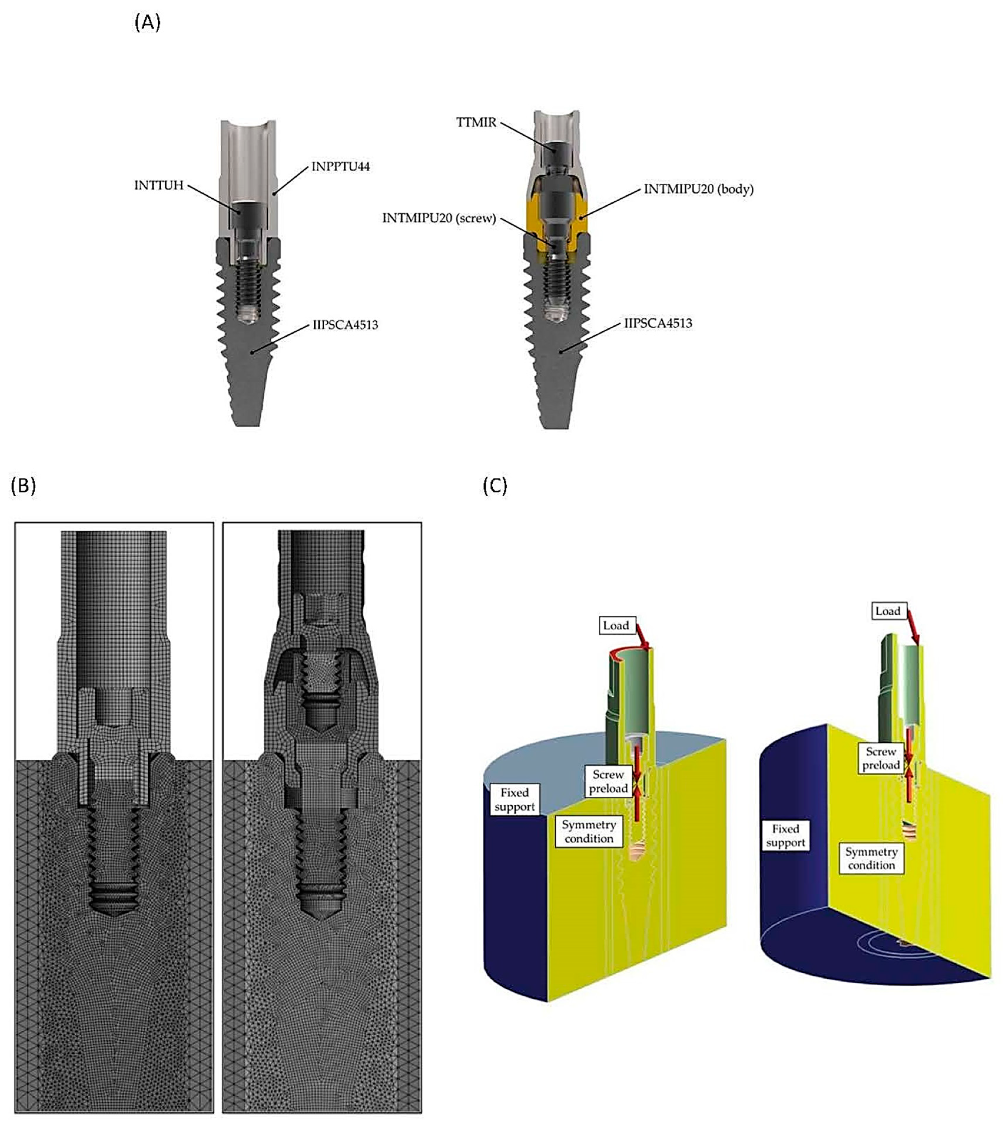
An IIPSCA4513 Interna Plus implant (BTI Biotechnology Institute, Miñano, Spain) with a diameter of 4.5 mm and a length of 13 mm was selected. Two implants were inserted into the cortical bone juxtacrestally, that is, leaving the implant-abutment platform at bone level. In the first case, an INPPTU44 abutment (BTI Biotechnology Institute, Miñano, Spain) was mounted. The post was attached to the implant using an INTTUH screw (BTI®, Miñano, Spain) tightened to 35 Ncm. In the second case studied, an INTMIPU20 transepithelial abutment was mounted on the implant and tightened to 35 Ncm. A CPMIUPU abutment (BTI Biotechnology Institute, Miñano, Spain) was mounted on top and was joined to the assembly using the TTMIR prosthetic screw (BTI Biotechnology Institute, Miñano, Spain), tightened to 20 Ncm.
The implants, abutments, and transepithelial bodies were made of pure grade 4 titanium (Ti CP4), while the screws (including the one that comes with the transepithelial) were made of Ti6Al4V ELI (extra-low interstitials) (Ti Gr 5); the chemical composition is shown in
Table 1.
Figure 1A shows the 3D models of the two dental restorations used in this study (direct-to-implant vs. using an intermediate abutment). The FE analyses were performed using Ansys Workbench
® 19R1 (Ansys Iberia S.L., Madrid, Spain). A (cyclic) chewing force was simulated with an inclination of 30° with respect to the vertical, as indicated in ISO 14801 [
25].
In general, two types of loads have been applied in many studies—the vertical load and the 30° oblique load [
24]. In order to consider a more severe case, one which is possibly also more realistic, the load was applied at a 10.5 mm height from the implant–abutment connection (IAC) [
26]. The stress level of the implant increases with the increasing crown height, which appears to be a more critical factor than the crown–implant ratio. This is related to the class I lever effect. The fulcrum, load arm, and effort arm should be considered carefully to understand the stress distribution of the implant restoration [
24].
Taking advantage of the symmetry of both the load and the model geometry, only half of the restoration was modeled; consequently, half of the preload and external load was applied. The threads of the screws and the internal thread of the implant were modeled as cylindrical threads instead of helical threads since this simplification does not imply an error greater than 3.5% [
27].
Figure 1B shows the mesh of the two models under study (direct-to-implant vs. using an intermediate abutment), with a total of 2.7 million degrees of freedom (DoF). Both of the titanium materials were modeled as linearly elastic with Young’s modulus (E) = 103 GPa, Poisson’s ratio (v) = 0.35 for CP 4 and v = 0.31 for Gr 5, while the cortical bone was also modeled as linearly elastic, with E = 13 GPa and v = 0.37. The contacts were defined as frictional contacts with friction coefficients of 0.17 for the screw–implant, screw–post, and screw–transepithelial contacts, and 0.21 for the implant–post, implant–transepithelial, and transepithelial–cylinder contacts [
28].
Figure 1C shows the load, preload, fixed support, and symmetry condition of the system. However, the contacts are not shown, as there are so many that the authors could not find a way to show them all clearly.
The FEA performed consisted of two or three load steps, depending on the case under study. First, the screw preload corresponding to the recommended tightening torque was applied by means of a pretension section. In the case of the direct-to-implant restoration, this was performed in the first load step. In the case of the transepithelial-supported restoration, a first load step was necessary to preload the implant screw, and a second load step was needed to preload the prosthetic screw on the transepithelial component. This preload was calculated using the Motosh formula [
27] and resulted in 814 N (direct-to-implant), 688 N (transepithelial), and 572 N (prosthetic screw over transepithelial). In a similar study, the preload of 825 N as a body force was applied to the upper part of the shank of the abutment screw, where the elongation of the screw was expected with tightening. Once the screw preloads were applied, a final loading step was used to apply the masticatory load with values from 0 to 400 N. The simulated bite forces employed in our finite element study were up to 400 N, as in other similar studies [
29].
From the FEA, the contact reactions at the screw head were obtained: axial force, transverse force, and bending moment. These forces, once transferred to the critical section, the first thread in contact were used to calculate the nominal stress in this section. As the load cycle determined by ISO14801 [
25] varies sinusoidally from the maximum load, and from 10% of this load, the nominal stress value at these two values of the load cycle were recorded. With both nominal stress values obtained, the effective fatigue stress was determined in order to later compare its behavior under a succession of masticatory loads. The finite element models used in this study are based on previously published studies [
27,
28,
30] and a PhD thesis [
31]. The results obtained through these finite element analyses were validated experimentally, providing very accurate results.
In this work, force reactions in screw contacts were considered. The structural behavior of a component does not need as high of a mesh refinement as for obtaining an accurate peak stress. Nevertheless, a minimum refinement must be performed to ensure proper contact behavior among components. In the following table, three mesh refinement grades are compared to determine the proper mesh. Force reactions were compared for the same instant during the analysis. The analyses were named from A to C, A being the least refined and C the most refined mesh.
Table 2 shows the DoF used for each mesh.
Figure 2A,B shows the axial force (2A) and bending moment reactions (2B) for a 0–400 N masticatory load range. As it can be appreciated, the axial force showed almost identical values regardless of the mesh. Regarding bending moment, only if a very coarse mesh is applied do the obtained values change. If a mesh refinement between B and C is performed, the moment values will not vary. In this study, the B mesh was used since it has been proven to be sufficient for accurate results.
Finally, in order to verify that the breakages were produced by the site given by the FEM, a cyclic load was applied to three samples of each of the two dental restorations under study: the direct-to-implant and the transepithelial-supported restorations. The load was applied until a breakage of the dental restoration was detected and the component on which the breakage occurred was identified. The tests were performed on an INSTRON E 3000 Electropuls fatigue bench (Instron, Barcelona, Spain) mounted with a DYNACELLTM 2527-153 load cell (Instron, Barcelona, Spain) with a load range of ±5-kN. The setup was the same as that described for the FE analysis modeling, except for the specimen holder, which, in this case, was made of steel rather than cortical bone. Moreover, in order to facilitate a correct load application, a hemispherical device was added over the abutment to ensure that the load was applied at 10.5 mm from the height of the implant platform, using FEA.
Figure 3A shows a direct tension fatigue machine with standard fixtures for testing material specimens, and
Figure 3B shows a specific set-up for conducting tests on dental restorations.
4. Discussion
In this study, we investigated how the use of a transepithelial component compares to a direct implant-supported restoration in terms of fatigue behavior. Given that one of the most common complications in single-unit restorations of implants is screw loosening or even fracture, it is intriguing to analyze the force distribution when adding an intermediate component. Additionally, investigating whether using a transepithelial abutment can prevent the unwanted fracture of the direct implant-to-screw connection, which could render the implant nonfunctional, is of significant interest.
We demonstrated that the component most likely to fracture is the screw of the intermediate abutment. In such cases, removing the fractured fragment or, in the worst-case scenario, the intermediate abutment itself is sufficient. Importantly, the implant remains uncompromised.
Considering the significance of the preload in preserving the structural and interfacial integrity of the implant abutment assembly, Honório et al. [
23] conducted a study to evaluate the impact of varying preloads on the stress experienced by the retention screw and the microgap width of the internal conical connection. They employed finite element analysis (FEA) with a well-established model for preload assessment. This research shed light on the optimization of the preload to enhance the performance and longevity of dental implant components. When the screw-tightening torque was increased from 20 Ncm to 30 Ncm, it led to higher stresses in the abutment screw throughout various phases: before, during, and after occlusal loads. However, this higher torque also had some interesting effects, such as smaller microgaps. The higher torque also increased the occlusal load required to bridge the internal implant space. This could potentially help reduce bacterial leakage. Interestingly, the study found that the maximum stress in the abutment screw occurred at its neck on the distal surface. This suggests that the screw is more likely to fail in this specific region [
23], which is consistent with the results obtained in our study.
Furthermore, FEA can be used for sensitivity analysis to study the effects of varying the material and geometrical parameters, such as the coefficient of friction, the screw diameter, the screw design, and the length of the implant fixture. Within the range of loads (10 N–280 N) tested in this FEA study, the gap sizes, especially those within the bridging zone, may not be large enough for the invasion of bacteria, the size of which can reach 6 µm. Therefore, further studies are needed to correlate the interfacial gap opening and bacterial microleakage [
23].
In a FE study, Jung et al. [
19] investigated the effects of the abutment screw preload on two different implant connection systems. Six three-dimensional finite element models were created based on various conditions: EO, an external hexagonal connection system with preload only; EN, an external hexagonal connection system with occlusal load only (no preload); EP, an external hexagonal system with both preload and occlusal load; IO, an internal hexagonal system with preload only; IN, an internal hexagonal system with occlusal load only; and IP, an internal hexagonal system with both preload and occlusal load. An 11.3-degree oblique load (100 N) was applied to the crown’s occlusal surface for models with an occlusal load, and a preload of 825 N was applied to the abutment screw in the models. The abutment screw experienced the greatest increase in von Mises stress values under the occlusal load. The stress values ranged from 104.5 MPa (model EN) to 850 MPa (model EP) and from 37 MPa (model IN) to 674 MPa (model IP). Following the implant, the abutment showed the next highest stress levels. This study highlights the importance of considering preload conditions and connection system designs when evaluating the biomechanical behavior of dental implants. Understanding stress distribution patterns can contribute to the long-term success of implant-supported restorations [
19]. Regardless of the conditions of the occlusal load, the models with preloads showed higher stress values than the models without preloads in both the external and internal connection systems. It seems essential to include the preload condition in finite element analysis, as a preload applied to the abutment screw influences the stress level in the implant system and bone.
Verri et al. [
18] carried out a similar FE study to analyze the stress distributions of single implant-supported prostheses with different connections (external hexagon EH, internal hexagon IH, or Morse taper MT) in the anterior region of the maxilla, while varying the inclination of the applied load (0, 30, and 60 degrees) and the surgical technique for implant placement (monocortical/conventional, bicortical, and bicortical with nasal floor elevation) [
18].
In this study conducted by Verri et al. [
18], the EH implants exhibited higher stress levels on the fixation screw and implant, ranging from 100 to 600 MPa. However, these stress values did not necessarily affect the implant viability. The stress primarily indicated a mechanical tendency to result in issues such as screw loosening or failure, rather than a biological risk. The study found that the worst situations occurred under 60-degree loading. It is important to note that implants in clinical practice are typically not subjected to such large oblique forces. The internal connection implants showed a tendency toward implant-related problems. However, the amount of stress required to loosen the fixation screw of an EH implant should be less than the stress needed to fracture titanium. This observation might explain why EH implants are sometimes associated with more biomechanical issues than IC implants [
18].
4.1. Impact of the Design of the Restoration
Whether prosthetic restorations supported by implants of different sizes and diameters placed adjacently should be separate or splinted is unclear. While splinted restorations may offer advantages in terms of stress distribution, individual patient factors and clinical realities play a significant role. The restoration designs can change the stress levels in adjacent implants of different lengths and diameters. Kul et al. [
21] analyzed the stress and strain distribution around short and standard implants in the posterior mandible with splinted and separate crowns. The practical clinical considerations resulting from this study include the importance of an optimal and stable implant–abutment connection that plays a crucial role in the long-term success of dental implants because the stress is reduced. Oblique loads (loads applied at an angle) have a greater moment effect than purely vertical loads. As the angle between the direction of the oblique load and the implant axis increases, the moment effect becomes more pronounced. These oblique loads can significantly influence the stress distribution in implant-supported restorations. If a standard implant and a short implant are placed adjacently and restored with splinted crowns, the implants, abutments, and screws may be damaged; therefore, adjacent splinted implants should be of similar size. However, the perfect fit of the implant–abutment junction reduces stress, even in these adverse situations [
21].
Other variables that should be taken into account during the manufacture of our restorations are the retention system (usually either screw- or cement-retained) and the type of restorative material used, which can also affect the stress distribution. For many years, metal–ceramic prostheses have been considered by some clinicians to be the gold standard of rehabilitation with an implant-supported prosthesis. Currently, there is increasing demand for metal-free restorations, such as those consisting of zirconia, as a more aesthetic rehabilitative treatment option. Lemos et al. [
33] evaluated different implant–abutment connections, retention systems, and restorative materials in single crowns using 3D FEA. There was a higher concentration of stress in the fixation screw for the cemented prostheses in the external hexagon implants independently from the restorative materials used (increasing the risk of screw loosening/fracture). Furthermore, it should be acknowledged that in the event of screw loosening, the solution is more complex than in the screwed retention systems. Therefore, the combination of an external hexagon implant and a cement-retained prosthesis should be avoided [
33].
Metal–ceramic and zirconia monolithic implant-supported single crowns had similar biomechanical behaviors in bone tissue and implants and their components. For Lemos et al., the similarities between the metal–ceramic and zirconia monolithic prostheses may be attributable to the similar mechanical properties, which may contribute to the sharing of stress across structures [
33].
However, other researchers such as Pumnil et al. [
34] present different evidence for the influence of the material on the transmission of loads. A comparative 3D FEA study of the stress distribution in the implant, screw, Ti-base, abutment, and restorative crown between the different customized abutment types has not been evaluated, and the proper abutment type selection for the implant-supported single crown is still an ambiguous issue. Therefore, Pumnil et al. [
34] introduced a study to investigate the stress distribution using 3D FEA on the implant, screw, Ti-base, abutment, hybrid–abutment crown, and restorative crown among different abutment types, as follows: customized titanium abutment, customized titanium hybrid–abutment crown, customized zirconia abutment with Ti-base, and customized zirconia hybrid abutment crown with Ti-base. For all groups, oblique loading tended to generate higher stress values compared to purely vertical loads. Clinicians should avoid excessive oblique forces to prevent stress-related complications. Pumnil et al. [
34] concluded that the choice of abutment type significantly impacts the stress distribution in implant-supported restorations. The presence of a titanium base within a zirconia abutment improved the stress distribution. Titanium has the ability to absorb stress, contributing to overall stability. This combination is a favorable option for implant-supported crowns. A customized titanium hybrid–abutment crown created stress concentration at the screw; thus, this abutment type should be used cautiously and maintained regularly. In addition, a customized zirconia hybrid–abutment crown with a titanium base caused stress concentration at the implant, and this abutment type should be maintained regularly. A thoughtful selection of abutment materials and diligent maintenance are crucial for successful implant restorations [
34].
4.2. Impact of Intermediate Abutments
With regard to the use of intermediate abutments, Zincir et al. [
20] compared the stress and strain values of the direct-to-implant system with the conventional angled multiunit abutment–implant connection system used in “all on four” rehabilitations in the implant parts and the surrounding bone using FEM. In the context of axial and oblique forces, they found that the direct-to-implant systems exhibited greater stress accumulation in the bone, prosthesis screws, and implants when compared to multiunit abutment–implant connection systems [
20]. These results are in line with those reported in this study.
As seen in the stress map of the screws of the two dental restorations (
Figure 5) in the case of transepithelial-supported restorations, the top screw is the one that would break in the event of an overload. This prevents the rest of the restoration from being damaged. This study, based on the previous literature, was performed with the assumption that the maximum functional force was 400 N [
19,
23]. Occlusal loading of 100 N is considered to correspond with light clenching while loading of 200 N is considered to correspond with middle clenching [
35]. We wanted to understand how stress is distributed within the system when it faces extreme loads, such as those experienced by bruxism patients. Our goal was to identify the most vulnerable parts of the system (
Figure 4). Additionally, we observed that in S–N curves (
Figure 5), stress on the screws exponentially increases with load. This observation aligns with the finding that bruxism patients tend to experience greater mechanical complications compared to non-bruxism individuals [
36].
It is worth mentioning that the stress level of the upper screw (
Figure 5) indicates that the fatigue life of the screw of the intermediate abutment would be slightly lower than in the case of direct-to-implant restoration. However, the difference is minimal; so, this reduction in fatigue life may not be relevant in the patient’s mouth. In any case, as mentioned above, the fact that the upper prosthetic screw acts as a fuse serves to protect the rest of the dental restoration. It is beneficial that the fracture is usually of the abutment screw, as we have seen in this study. Furthermore, in the case when a repair is needed, this would be conducted at the tissue level, that is, with the replacement of the upper screw and possibly the abutment, without touching the implant–abutment connection or the bone surrounding it. Therefore, these advantages far outweigh the minimal reduction in fatigue life.
However, there are additional potential benefits. Even if the screw does not break, when screw loosening occurs, there are biological implications. The microgap at the implant interface permits fluid passage independently of the implant system. Functional rocking effects and screw loosening may contribute to increased leakage. Moreover, the clinical phenomenon of bleeding and malodor, which are attributable to anaerobic bacteria on the removal of abutments or healing screws, may partly be the result of the effects of microleakage [
37].
When the implant–abutment interface is positioned at the alveolar bone level, it leads to persistent peri-implant inflammation and significant bone loss. This suggests that the inflammatory stimulus originates precisely at the implant–abutment interface, and there is a direct relationship between the extent of the inflammation and the magnitude of the alveolar bone loss [
38].
Abutment screw loosening, as mentioned above, is a common mechanical complication in dental implants. It occurs primarily because the abutment screw is the weakest part of the implant system. Stable connections between implant components are crucial for treatment success. A review by Goodacre et al. [
39] revealed that screw loosening occurs in 8% of cases, and this figure can rise to 45% in single crowns. Additionally, abutment screw loosening may lead to other complications, including screw fracture, marginal gaps, peri-implantitis, microbial leakage, crown loosening, and patient discomfort [
40].
To mitigate this complication, it is essential to ensure an optimal component fit, minimize the abutment micromovement, reduce the prosthetic misfit, optimize the prosthetic design and occlusion, and maintain a sustained preload [
37].
The use of an intermediate abutment in single–implant restorations offers several advantages. Firstly, the implant–abutment interface remains better sealed, avoiding disconnection during prosthesis fabrication. This inherently reduces contamination and minimizes microleakage around the implant platform. Additionally, as mechanical overload primarily affects the abutment screw, it is more likely to loosen. Importantly, this loosening occurs away from the bone crest, mitigating potential biological complications and preventing marginal bone loss.
Although the use of intermediate abutments has been more commonly accepted in multiple implants, it is not as common in single implants. Not all commercial implant manufacturers offer this possibility yet. However, following the results of this study, we can emphasize that, among the other advantages already described regarding the use of an intermediate abutment, in the event of a fracture of the abutment screw, it would be possible to remove it and put in a new one. In the worst-case scenario, when trying to rescue the fragment of the screw, the abutment could be damaged but not the implant. Additionally, in the event of screw loosening, it would not happen at the implant–abutment interface. Consequently, there may be a reduction in biological complications related to microfiltrations, although research and further investigation are essential to advance our understanding and to address unanswered questions.
Limitations of the study: Finite element analysis (FEA) has its limitations, and critical considerations are necessary when interpreting its results. FEA relies on input material properties, which may not perfectly mimic real-world conditions. Variations in material behavior can impact simulation outcomes. Clinicians should be cautious when directly applying FEA findings to clinical practice because it is a virtual model and cannot fully replicate the complexities of biological tissues. Clinical validation is essential to confirm the observed biomechanical effects. However, FEA provides valuable insights, and its findings should be complemented by empirical evidence from clinical studies. Moreover, our investigation was restricted to a particular brand of implant and a specific material. However, it is essential to recognize that contemporary clinicians have an array of options available, including various brands and materials for implants and implant components. Notably, zirconia and diverse metal combinations are among these alternatives. By acknowledging these limitations, we demonstrate both our awareness of this study’s scope and our commitment to transparent reporting. Furthermore, we encourage future research to explore broader material choices and their implications.
Practical clinical applications: With the results obtained in this study, we can affirm that the use of intermediate abutments may be beneficial when rehabilitating single-unit implants. The use of these abutments has been relatively common in multiple implant rehabilitation; however, it has been less common in single-unit implants. The biomechanical advantages that their use can provide appear to be proven.
Future research directions: Future studies that incorporate even more sophisticated models are essential. These studies would allow for a comprehensive evaluation of, for example, the impact of simulating the preload condition in the abutment screw during advanced finite element analysis (FEA) applications. By considering these factors, researchers can gain deeper insights into the behavior of implant-supported restorations and enhance clinical outcomes.
It should be taken into account that this study was limited to the analysis of the mechanical behavior of a specific transepithelial abutment model. There are transepithelial abutments with different prosthetic emergences and it is possible that these different prosthetic platforms would have an influence on the behavior of the prosthetic screw (the upper screw). This study is proposed as a future line of the current research.
The authors’ objective is to conduct a clinical trial that applies the insights derived from this study, thereby substantiating its clinical validity.


 ,
, 


