
Quo Vadis: AlCr-Based Coatings in Industrial Applications
by
Joerg Vetter
1,*, 
Anders O. Eriksson
2, 
Andreas Reiter
2,
Volker Derflinger
2 and
Wolfgang Kalss
2 1
Oerlikon Balzers Coating Germany GmbH, Am Boettcherberg 30–38, 51427 Bergisch Gladbach, Germany
2
Oerlikon Balzers, Oerlikon Surface Solutions AG, Iramali 18, LI-9496 Balzers, Liechtenstein
*
Author to whom correspondence should be addressed.
Coatings 2021, 11(3), 344; https://0-doi-org.brum.beds.ac.uk/10.3390/coatings11030344
Submission received: 12 February 2021
/
Revised: 12 March 2021
/
Accepted: 15 March 2021
/
Published: 18 March 2021
(This article belongs to the Special Issue Technologies of Coatings and Surface Hardening for Tool Industry)
Abstract
:AlCr-based hard nitride coatings with different chemical compositions and architectures have been successfully developed and applied over the last few decades. Coating properties are mainly influenced by deposition conditions and the Al/Cr content. The fcc structure is dominant for an Al-content up to Al0.7Cr0.3N and is preferred for most cutting applications. Different (AlCrX)N alloying concepts, including X = Si, W, B, V, have been investigated in order to enhance oxidation resistance and wear behaviour and to provide tribological properties. AlCr-based oxynitrides and even pure oxides (Al1−xCrx)2O3 with different crystalline structures have been explored. Multi- and nanolayered coatings within the AlCr materials system, as well as in combination with (TiSi)N, for example, have also been implemented industrially. The dominant deposition technology is the vacuum arc process. Recently, advanced high-power impulse magnetron sputtering (HiPIMS) processes have also been successfully applied on an industrial scale. This paper describes basic coating properties and briefly addresses the main aspects of the coating processes as well as selected industrial applications.
Keywords:
AlCr-based; CrAl-based; (AlCrX)N; (Al1−xCrx)2O3; arc; HiPIMS; nanolayers; nanocomposite; structure; properties1. Introduction
Surface solutions using PVD (Physical Vapor Deposition) coatings for the improvement of the wear resistance and tribological properties of tools and components started on an industrial scale around the middle of the 1970s in the Soviet Union. The first component coating was MoN [1]. The first successful industrial coating for tooling applications in Western Europe was the “golden” TiN coating applied by low-voltage arc evaporation developed at Oerlikon Balzers [2]. A modification of this coating with carbon followed, and the TiNC coating types were implemented in mass production at the end of the 1980s. In parallel, Cr-based coatings were also introduced, including modifications using oxygen and carbon [3]. Besides nitride, carbonitride and oxynitride coatings, hard amorphous carbon coatings, the DLC (Diamond Like Carbon) coatings, were developed and applied as well [4,5]. These coatings were deposited using several coating architectures [6]. Many coating developments focused on alloying TiN using different additional elements [5].
The most important industrial development after TiN, CrN and DLC was achieved in the Ti-Al-N system [7]. Around the year 2000, this coating family was the dominant coating, especially for cutting tools [8,9]. However, in the Ti-Al-N system, only minor improvements of coating properties and the performance of cutting tool applications were possible, e.g., by alloying with Si, Y, Cr, C, O [10,11,12,13]. A big step forward was achieved through the investigation of totally new coating compositions. This led to the development of a new coating generation based on Al-Cr-N. Coatings in the AlCrN system span the compositional range from Al-rich to Cr-rich. In this paper, the terminology CrAl-based is used for coatings with a Cr content that is higher than that of Al (Cr/Al > 1 in at.%), and conversely, AlCr-based is used for coatings in which Al/Cr > 1.
Results dealing with coatings with a low Al content (Al/(Al + Cr) ratio < 0.5) and (CrAl)N coatings, deposited by sputtering, were published for the first time in 1990 [14,15]. In the same year, coatings with an Al/(Al + Cr) composition of about 0.5 deposited using a modified hollow cathode discharge process were also presented [16]. Arc evaporation was used to deposit (AlCr)N coatings with a high Al content with an (Al/(Al + Cr) ratio of >0.5 [17,18]. The first multilayer coating with an Al content greater than the Cr content was a multilayer architecture with CrN [19]. Another big step was the development of (TiSi)N coatings [20]. Coating solutions were also developed which combined the two coating types in multilayer structures [21].
A challenge for turning tools was, and still is in part, the development of alpha-alumina using PVD. A PVD solution to add metallic doping elements to aluminium was patented in 1992 [22]. Processes to deposit oxides based on arc evaporation were successfully developed on the basis of Al-Cr cathodes [23].
This paper will review the main industrial-oriented coating developments using CrAl- and AlCr-based coatings, covering a wide variety of chemical and structural fields as well as architectures. The main deposition methods used will be described briefly. The review will concentrate on arc deposition processes, although sputtering techniques, including high-power impulse magnetron sputtering (HiPIMS), will be discussed as well. The main focus is on arc deposition processes and nitride coatings with an Al content greater than the Cr content and on (AlCr)ON coatings. Coatings with a cubic structure and various multilayer coatings are used most commonly in industrial applications. Selected application examples will be presented in the last section.
2. Deposition Technologies and Coating Systems
Various deposition technologies have been used to synthesise (CrAl)N and (AlCr)N coatings over a period of about 30 years. Basic information about the deposition technologies is beyond the scope of this review. The interested reader is invited to look at available publications [24,25,26,27,28,29,30,31]. Some more exotic evaporation methods are hollow cathode arc evaporation [16] and activated reactive evaporation [32]. The first application of AlCr-based coatings for cutting tools deposited by hollow cathode arc was mentioned very early [16,33]. However, primarily sputtering processes and arc processes were used both for basic investigations as well as for applications.
The first reported (CrAl)N coatings were DC (Direct Current) magnetron sputtered [14,15]. The first arc coatings were deposited using elemental cathodes of pure Al and pure Cr [17]. The first multilayer coating (AlCr)N was (AlCr)N/CrN deposited by arc [19]. Sometimes even hybrid methods, such as arc plus hollow cathode discharge [34] or, more commonly, arc plus sputtering [35], have been used. Alloyed CrAl-based and AlCr-based coatings are most commonly deposited either by magnetron sputtering or by arc evaporation. For sputtered coatings, the preferred methods are various HiPIMS processes in industrial applications, e.g., the S3p process [30]. The deposition of alpha alumina coating is based on a dedicated pulsed arc process, the P3e process [23].
It should be mentioned that the main differences between arc deposition processes and sputtering are:
Growth defects: Arc-deposited coatings have more growth defects in the coating than sputtered coatings due to macroparticle generation in the arc evaporation process. Sputtered coatings are thus preferred in applications requiring particularly low surface roughness.
Growth rate: The arc process allows a higher growth rate to be achieved than sputtering, depending on the PVD system set-up.
Degree of ionisation and ion energies: Arc evaporation is known to produce plasmas with a high degree of ionisation. Multiple charge states are formed as well in arc evaporation [36]. Sputtering processes are characterised by lower degrees of ionisation [26].
Energy consumption: The specific energy consumption of the arc process is lower than that of sputtered coatings for the same coating thickness [37].
Process stability: Arc processes tend to exhibit higher process stability than sputtering processes.
Larger coating volumes: Arc processes can be more easily upscaled for coating long parts (several metres).
The different basic methods used for CrAl-based and AlCr-based coatings are listed here briefly.
2.1. Arc Deposition Methods
CrAl-based and AlCr-based coatings are deposited by reactive direct vacuum arc using either elemental cathodes or composite cathodes. The first (CrAl)N and (AlCr)N coatings were deposited by the reactive co-evaporation of elemental chromium and aluminium cathodes available at that time [17,18,19].
The first composite cathodes suitable for arc evaporation manufactured by a powder metallurgical process were produced by Plansee AG, Austria, and were used successfully for tool coatings in 1995 [38]. Later, composite cathodes became the standard, especially in industrial applications [39,40]. A special pulsed process was developed for alpha (Al1−xCrx)2O3 coatings, the P3e process [23]. The main goal of the pulsing is to overcome process difficulties generated by the oxide process (cathode, anode reactions).
2.2. Sputtering Methods
2.2.1. DC and RF Sputtering
Several sputtering methods as well as combinations of different sputtering methods have been used to deposit both CrAl-based and AlCr-based coatings from elemental or composite cathodes. Even special processes based on the combination of composite targets combined with elemental targets have been realised [41]. The first CrAl-based coatings were deposited by reactive DC magnetron sputtering of a composite target (Cr75Al75) [14,15]. Additionally, newer research on a laboratory scale as well as industrial-scale PVD systems are using DC magnetron sputtering [41,42,43,44,45,46]. It should be noted that special magnetic field configurations can be achieved within the PVD systems by means of the magnetron set-ups, e.g., the CFUBM (Closed Field Unbalanced Magnetron Sputtering) [47,48]. RF (Radio Frequency) sputtering has been used for basic investigation [49,50]. Even the combination of RF sputtering plus DC sputtering has been applied [51,52], though RF sputtering is typically not used for industrial applications.
2.2.2. Standard Pulsed Sputtering and HiPIMS
Besides standard pulsed magnetron sputtering [41], the mode of dual pulsed magnetrons has also been used [48]. The most advanced pulsed sputtering method is high-power impulse magnetron sputtering. Pulses with peak power densities in the range of several hundred W/cm2 up to several thousand W/cm2 are achieved in classic high-power impulse magnetron sputtering (HiPIMS), also referred to as HPPMS, MPP or HIPAC. The pulse duration is usually in the range of 25 to 250 μs [41,53,54,55,56]. The longest pulse lengths of around 1000 μs are used in the case of MPP [57].
A dedicated HiPIMS process, known as the S3p process, is a process that runs with a constant pulse current and can operate using longer pulses than the classic HiPIMS process. The pulse duration often lies in the range of several milliseconds [30].
2.3. Industrial Coating Systems
A brief description of selected aspects of industrial systems will be provided here. In-depth descriptions of deposition systems are available elsewhere [27,30]. Both system configurations, set-ups with magnetrons and set-ups with arc evaporators, use particle sources with either a circular, rectangular or tubular geometry for the active evaporation surfaces, as shown in Figure 1. The circular form dominates for arc evaporation, whereas the rectangular and the cylindrical forms are used most commonly for sputtering. In addition to arc and sputtering systems, hybrid systems, e.g., arc plus HiPIMS, are also in use [29].
For the deposition of AlCr-based coatings, powder metallurgically manufactured composite targets are used most commonly. Sputtering has the advantage that composite targets in the form of segmented targets or targets with plugs of a second type of material (e.g., Cr plugs in Al target plates) can also be used [48].
Modern coating systems run in fully automatic operation. They must fulfil the following criteria with respect to high productivity and quality: high production reliability, short cycle times, high flexibility in coating types and substrate holders, easy maintenance. Additional aspects are CE (Conformité Européenne), conformity and high occupational safety standards. Environmental sustainability is also gaining importance, including the influence of factors such as energy consumption.
Of course, the basic components of the coating systems must also be optimised, e.g., vacuum pumps, power supplies, particle sources, heaters, substrate holders. In addition, all process steps including loading, pumping, heating, ion cleaning, coating, cooling, unloading and maintenance must be optimised for short cycle times and efficient operation. The choice between batch systems or inline systems depends on the use and the required flexibility. Batch systems are predominant for industrial coating applications. The system size is selected based on the expected batch size as determined by the dimensions and number of parts to be coated, but also by operating economy.
The usable volume of a batch system is defined by the interior size of the deposition chamber. Usually, coating systems are designed with a circular geometry along a central axis, allowing the rotation of substrates. The maximum useful volume therefore constitutes a cylindrical body. Small coating systems typically have a diameter of <0.5 m and a height of <0.5 m, which is adequate for small-scale series or research facilities. Medium size systems, with roughly a diameter of 1 m and a height of 1 m, are predominant in industrial production. Figure 2 shows an arc system equipped with circular arc evaporators, and a coatable diameter of 0.7 m and a height of 0.9 m. Special-purpose systems are available for large-scale manufacturing, with roughly a diameter of 1.5 m and a height of 1.5 m. Systems for oversized parts, such as broaches or plastic extrusion screws, have a coating height of up to 4.5 m.
3. Basic Properties of CrAlN and AlCrN Coatings
CrAl-based and AlCr-based coatings deposited by arc evaporation processes or by magnetron sputtering are widely used for cutting tools, moulds, dies and for various components. The success of these coatings with their predominantly fcc structure is due to their outstanding mechanical and tribological properties (such as high hot hardness, good abrasive and sliding wear resistance) combined with high oxidation and corrosion resistance. The present chapter highlights selected basic coating properties.
To begin with, an important remark must be made on the way the coating composition is reported in papers. A full compositional characterisation, including metallic and non-metallic elements as well as impurities such as oxygen, is the most complete, but is not always reported. Several publications neglect the stoichiometric aspects, the deviation of coating composition from the cathode/target composition, and the incorporation of residual gas components. Sometimes, only the cathode/target composition or only one of the values Al/Cr or Al/(Al + Cr) are given, presumably because methods such as EDS are most suited for the characterisation of metallic and heavy elements. Many papers state that the coatings consist stoichiometrically of 50 at.% metallic and 50 at.% non-metallic elements, and they are simply described as (Al1−xCrx)N.
One positive example is described for arc-deposited coatings using cathodes of Al70Cr30. The coating was characterised by XPS as having Al 33.1 at.%, Cr 15.8 at.%, N 48.1 at.%, and O 3.0 at.%. The metallic content is thus 48.9 at.% and the non-metallic content is 51.1 at.%. The ratio Al/(Al + Cr) is 0.68, meaning 68 at.% of the metallic content is Al. This corresponds to a deviation of 2 at.% from the cathode material. The Al/Cr ratio in the coating is 2.09. The coating contains oxygen from the residual gas. The coating is slightly over-stoichiometric [58]. The total formula has to be (Al1−xCrx)(N1−wOw) plus the stochiometric ratio (Al1−xCrx)/(N1−wOw). Unfortunately, however, detailed compositional data are not reported in many publications.
As a guide for the reading of coating compositions, the following terminology is used throughout this paper.
- If only the cathode composition is given and the stoichiometry in the coating is assumed to be equivalent to the cathode composition, the coating is described as (Al(100−x)Crx)N with 100 in at.%, e.g., (Al70Cr30)N.
- If the metallic elements (and metalloids) were measured, but only a general statement about the stoichiometry is made, the coatings are described as (Al(100−x)Cx)N with 100 in at.%, e.g., (Al70Cr30)N.
- If both metallic elements (and metalloids) and the N, O (and C) content were measured, all values are given as AlxCryNuOw, where x + y + u + w = 100 at.%, e.g., Al33Cr16N48O3.
3.1. The Influence of Al Content on Lattice Parameters, Phases and Microhardness
A schematic diagram of different basic crystal structures as a function of the Al portion of the coating’s metallic content in at.% is shown in Figure 3. It should be mentioned that in publications, the formula Cr1−xAlxN or Al1−xCrxN is sometimes used for the same coating in dependence on the Al content. Nowadays, the most commonly used terminology in industrial applications is the short name (AlCr)N for Al-rich coatings. The authors suggest that coatings with a chemical composition in at.% of Cr > Al should be named (CrAl)N. If Al > Cr, then the coating should be named (AlCr)N. (CrAl)N coatings always have an fcc crystal structure. This structure type is also referred to as B1, a NaCl structure or c in certain publications, depending on the convention. With increasing Al content, a phase evolution to an hcp crystal structure takes place, which is also referred to as B4, a ZnS-type structure, wurtzite, w, h or hcp in publications. In the following, fcc and hcp will be used.
XRD investigations of rf-sputtered coatings have shown that at 57 at.% Al, a pure fcc structure was obtained, while at 75 at.% Al, the hcp structure was observed. The transition range between fcc and fcc + hcp was in the range of 57 at.% < Almax < 67 at.% [49]. With pulsed closed-field magnetron sputtering, the formation of hcp phases was observed at an Al content of 64 at.%, whereas fcc phases were detected at up to 60.9 at.%, giving a transition range of 60.9 at.% < Almax < 64 at.% [59]. A systematic experimental investigation of (CrAl)N and (AlCr)N coatings synthesised using the cathodic arc method showed that the crystal structure changed from a pure fcc structure to a mixed-phase structure of fcc and hcp at an Al content of about 60–70 at.% of the metal content in the cathodes [60], whereas an fcc structure was observed at up to 71 at.% in the coating by the authors of [61].
The reported different maximum Al contents for the X-ray-diffraction-measured pure fcc phase differ over a range of about 60–70 at.%, as shown in Table 1.
The deposition process itself (source properties, parameters) has an influence at the maximum Al concentration on whether a pure fcc phase is obtained using X-ray diffraction, as will be shown for arc evaporation in Section 3.4.
Taking measurement uncertainties into account, a well-accepted maximum critical value of the transition is about 70 at.% Al [61,62,63,64,65,66]. It should be mentioned that coatings with Al contents of 65–70 at.% might contain some traces of hcp phases, which may, however, be difficult to detect using XRD. For example, this effect was observed with SAED (Selected Area Electron Diffraction) measurement of (AlCr)N coatings deposited using arc evaporation from cathodes of Al70Cr30 on sapphire [62]. The critical value of the transition from fcc to the mixed fcc plus hcp structure also depends slightly on the deposition conditions, influenced, for example, by the evaporator magnetic field set-up analogously to AlTiN [9], but bias and deposition pressure also have an influence on the “fine” structure in the area of the transition [45].
Figure 4 shows experimental results for the hardness and lattice parameters of arc-deposited (CrAl)N and (AlCr)N coatings [60,61]. Both studies show a hardness increase of about 60% compared to CrN for fcc-structured coatings in the range of Al 60–70 at.%. The differences in the absolute values are likely related to different deposition techniques and hardness measurement conditions. Furthermore, in the region of the mixed-phase structure of fcc + hcp at high Al-content, the hardness is equivalent to CrN. The lattice parameters decrease from 0.415–0.416 nm (CrN)) to 0.413 nm in the region of Al 60–70 at.%.
3.2. Mechanical and Physical Properties
3.2.1. Thermal Expansion
The thermal expansion coefficients (TECs) of fcc-structured (Cr,Al)N and (Al,Cr)N coatings deposited by sputtering were investigated using synchrotron X-ray diffraction at up to 600 °C [65]. It was shown that the thermal expansion coefficient increases with an increasing Al content, from about 7 × 10⁻⁶/K at room temperature to 10 × 10−6/K at 600 °C, see Figure 6. Higher mean values of 14.5 × 10⁻⁶/K were reported both for sputtered and arc-deposited (Al70Cr30)N coatings at room temperature [43]. A fair general estimate is thus (10.5 ± 3.5) × 10−6/K.
3.2.2. Thermal Conductivity
Figure 7 shows the thermal conductivity of (Ti50Al50)N, (Al66Ti34)N, and (Al70Cr30)N coatings [67]. The thermal conductivity is temperature-dependent and it is interesting to note that the thermal conductivity of (Al70Cr30)N drops at about 200 °C and, in the temperature range of 250–450 °C, is significantly lower than that of (Al66Ti34)N. The thermal properties of Cr25Al20.5Si4.5N50 coatings were measured using pulsed photothermal radiometry. A very low thermal conductivity of ca. 2.75 W/mK at room temperature and 3.5 W/mK at 400 °C was found [68]. PVD coatings exhibit a certain anisotropy of thermal conductivity perpendicular and parallel to the direction of growth. This effect is particularly pronounced for multilayer coatings. When engineering the thermal properties of a coated part, not only the intrinsic thermal conductivity of the coatings, but also the concentration and dimension of different growth defects, e.g., holes and droplets, must be taken into account [69].
3.2.3. Electrical Resistivity
3.2.4. Poisson’s Ratio, Young’s Moduli, Fracture Toughness
Ab initio calculations have shown that the Poisson’s ratio drops from about 0.27 for low Al contents to about 0.2 for an Al content of 70 at.% [70]. Figure 9 shows the ab initio calculated Young’s moduli (E) as a function of the Al content for fcc (Al,Cr)N [70,71]. Selected Young’s moduli measured by nanoindentation from [64,71] have been added.
The Young’s modulus increases with an increasing Al content. The same relative tendency, but with lower absolute values, was experimentally shown in [43]. The calculated values are in good agreement with measured nanoindentation moduli [64,72]. The Young’s modulus of (AlCr)N coatings drops significantly when the mixed-phase structure fcc + hcp is reached [43], as well as for Si-alloyed (AlCr)N coatings of, for example, Al33.4Cr18.3Si2.3N46O0.7 [73]. It should be noted that large variations of measured E values for fcc-(Al,Cr)N coatings have been published for coatings of nearly the same composition, for example, from 300 GPa (Al/(Al + Cr) content of 68 at.%) [73] to 469 GPa (Al/(Al + Cr) content of 63 at.%) [71]. Different sample conditions (thickness and substrate) and measurement systems themselves will influence the measured value.
In addition to the chemical composition, the Young’s modulus is also dependent on the grain size (grain boundary fraction), the compressive stress state, and the texture. A variation from 363 to 469 GPa was measured for Al28.4Cr 18.6N55 in different coating states. The high value was measured for a highly 100-oriented coating deposited on MgO (100) substrates [71]. Thus, a relatively wide variation of experimental results, besides the measuring conditions, must be anticipated.
The fracture toughness KIC of sputtered Al28.4Cr18.6N55 was measured by micromechanical bending tests at 1.3 ± 0.1 MPa √ m, which is lower than that of TiN at 2.0 ± 0.1 MPa √ m related to domain size effects, but it is possible to raise this in a superlattice combination of the two materials [71].
3.2.5. Thermal Phase Stability and Hardness after Annealing
The thermal stability of arc-deposited (CrAl)N and (AlCr)N coatings has been investigated through heat treatment in an Ar atmosphere with a hold time of 2 h at temperatures between 600 and 1300 °C in combination with XRD analysis [61]. The fcc structure was found to be stable up to 800 °C. Three reactions were observed sequentially for the (AlCr)N-system:
- Transformation of fcc (Al,Cr)N to hcp (Al,Cr)N at the grain boundaries first [74],
- Segregation of Cr2N,
- Segregation of pure chromium.
Above 900 °C, the entire coating transforms to a mixed-phase structure. No phase transformation occurred in the hcp-AlN coatings, as they were already in their thermodynamically stable state. This is shown schematically in Figure 10.
The effect of the annealing on the hardness of the same coatings was characterised as well, see Figure 11.
The highest hardness was shown for (Cr54Al46)N and (Al71Cr29)N, and was retained up to 800 and 900 °C, respectively. The subsequent drop in hardness at higher annealing temperatures is correlated with the phase decomposition [61].
The influence of the coating stress at the decomposition temperature was investigated by varying the deposition temperature. The coating deposition was performed by arc using Al70Cr30 cathodes. It was shown that the decomposition temperatures of the metastable fcc-(Al63.5Cr36.5)N phase depends significantly on the stress level in the coatings. The decomposition process starts at the same compressive stress level of around 4.3 GPa for all coatings that were investigated [75].
Figure 12 shows a comparison of the hardness after annealing at high temperatures for different commercial hard coatings, showing that the (Al70Cr30)N coating has the highest hot hardness for temperatures exceeding 950 °C.
3.2.6. Oxidation Behaviour
The oxidation behaviour of PVD hard coatings is an important property for applications such as dry high speed cutting and high temperature stressed components such as turbochargers. In a study of Cr-rich (CrAl)N sputtered coatings (Cr/Al = 2.94), a relatively small Al content (Cr44Al15N40 at.%) improved the oxidation stability compared to CrN [15]. The first publication about the oxidation characteristics of arc-deposited coatings (AlCr)N with a Al/Cr ratio > 0.5 showed a lower oxidation rate in comparison with CrN [19], as has been confirmed in further studies [51,61,76,77]. Oxidation tests of (CrAl)N and (AlCr)N coatings deposited by activated reactive evaporation showed excellent behaviour [32]. The authors stated that the investigated (CrAl)N and (AlCr)N coatings exhibited significantly better oxidation behaviour than TiAlN coatings, which has been confirmed in further studies [40,78]. A systematic comparison of the oxidation behaviour of arc-deposited (AlTi)N and (AlCr)N coatings, including long time exposure, was performed in [40]. It was shown that the oxidation resistance of both coatings improved with an increase in the Al content. The oxidation resistance of (AlCr)N coatings was significantly superior to that of (AlTi)N coatings. Figure 13 shows the oxide layer thickness of CrN, (CrAl)N and (AlCr)N coatings after annealing in the temperature range of 800 to 1000 °C in an ambient atmosphere for 30 min in 50 and 100 °C intervals. The addition of 20 at.% of Al to CrN deferred the start of oxidation by 100 °C and reduced the oxidation rate. The onset temperature for oxidation increased and the oxidation rate decreased with a further increase in the Al-content up to 71 at.% Al. At a higher Al content, significantly decreased oxidation resistance was detected for a coating with 83 at.% Al and for AlN. Oxidation then starts already at 800 °C. These coatings already have an hcp structure. The negative influence of the hcp structure on the oxidation resistance was confirmed by [79].
A model of the oxidation behaviour for both the onset temperature and the oxidation rate depends on the coating composition and the related phase structure, as described above. However, it was observed in general that Cr and Al ions diffuse to the surface, forming a dense oxide layer acting as a diffusion barrier, thereby limiting the inward diffusion of oxygen [32,76,80]. The onset of oxidation of fcc (Cr,Al)N and fcc (Al,Cr)N always starts with the dissociation to h-Cr2N and nitrogen in the coating. The presence of thermally stable Al–N bonding in the fcc-(Cr,Al)N structure can suppress the reduction of nitrogen in the coating. A dense (CrAl)2O3 or (AlCr)2O3 oxide layer (either amorphous or crystalline) is formed at an early stage of oxidation [76]. This can act as an effective diffusion barrier hindering the inward diffusion of the oxygen. All further reactions are influenced by the Al content at a given temperature.
It should be mentioned that there are several ways to increase the oxidation stability of (CrAl)N and (AlCr)N coatings, e.g., by means of synergistic alloying of the coatings with small amounts of Si [81], see also Section 4.4. By way of illustration, Figure 14 shows the excellent oxidation resistance of (Al70Cr30)N coatings in comparison to industrial-standard PVD coatings.
3.3. Selected Tribological Properties
The tribological properties of (CrAl)N and (AlCr)N depend not only on the coating properties, but also on the tribosystem itself (e.g., counterpart, lubrication, temperature, loads).
3.3.1. Dry Friction against Steel
The dry friction value of (AlCr)N coatings against steel is slightly higher than that of CrN at ca. 0.65 [19], as measured using the pin–on-disc method against hardened bearing steel, 100Cr6. A friction value for (AlCr)N of about 0.5 was reported for AISI4340 as a pin [82]. The friction value at low load (5 N) was similar to that of (TiAl)N, whereas at high load conditions (20 N), (AlCr)N displayed a significantly lower friction coefficient. The superior tribological behaviour, namely a low wear rate and low friction, of an (AlCr)N coating against AISI 4340 steel is associated with the higher proportion of distinct (dispersive-polar) interactions, as evidenced by the measured surface energies. (AlCr)N and (TiAl)N coatings have a high polar component of 19.8 and 15.4 mJ/m2, and a low dispersive component of 2.9 and 6.5 mJ/m2, respectively, while the AISI 4340 steel presented a similar proportion between the polar, 14.3 mJ/m2 and dispersive 13.5 mJ/m2 components [82]. Measurement of the dry friction of (AlCr)N coatings by pin-on-disc against austenitic stainless steel (DIN1.4301, AISI 304, hardness 274 HV1) showed a friction value of 0.85 at room temperature, which dropped to about 0.6 at higher temperatures [83].
3.3.2. Dry Friction and Wear against Ceramics
The coefficient of friction measured by pin-on-disc tests against Al2O3 balls for (CrAl)N and (AlCr)N coatings of different Al contents showed a friction coefficient of about 0.6 at room temperature, independent of the Al content [83]. The friction value increased for 500 °C and dropped to 0.6 again at 700 °C, and was also nearly independent of the Al content. Figure 15 shows the decreasing abrasive wear rate with increasing Al content for all investigated temperatures [83].
The dry tribological properties of arc-deposited (Al70Cr30)N, (Al67Ti33)N, and CrN coatings against a Si3N4 ball as the counterpart showed friction values of 0.73, 0.79, and 0.77 at the end of the test, respectively [84]. A special effect related to the wear rate was observed. The highest wear rate was measured for (Al67Ti33)N, but CrN had a slightly lower wear rate than (Al70Cr30)N. The authors claim this is caused by the tribological oxidation behaviour, which has a great influence on the wear mechanism and the debris removal behaviour of the coatings.
3.4. Control of Coating Morphology, Stress and Texture
(CrAl)N and (AlCr)N coatings synthesised using PVD processes display a rich variety of microstructures, from fine-grained morphology up to coarse columnar structures, which make different (AlCr)N coatings suitable for many diverse application areas. This section focuses on (AlCr)N coatings, though similar effects are also valid for (CrAl)N coatings. The relationships between the deposition parameters and the coating morphology are summarised in generic structure-zone diagrams [85] to provide guidelines that can be applied for (AlCr)N coatings in general. The deposition conditions can also be used to control the stress state of the coatings [86], which often is an important part of engineering coatings and in adapting them to different use cases and requirements. For example, thick coating layers are at risk of peeling off if the stress state is too high, while high compressive stresses can be advantageous in interrupted cutting operations. The stress state has also been pointed out as a key determining factor for thermal stability and decomposition pathways [75].
The effect of bias voltage on the stress state and coating properties of (AlCr)N coatings deposited using Al60Cr40 targets has been investigated systematically [87]. Increasing the bias voltage led to higher levels of compressive residual stresses as a function of the increased ion bombardment, up to a threshold in the range of 100 V, see Figure 16. Further higher bias values reduced the overall stress state, which was attributed to the annihilation of defects and stress relaxation. A concurrent reduction in grain size, the lattice parameter and a modified preferential orientation in XRD from (200) to a mixture of (200) and (111) were also observed as an effect of increasing the bias [87].
Similar trends for texture and increased hardness with bias were also reported for coatings deposited using Al70Cr30 and Al75Cr25 cathodes. Coatings with a higher Al content, deposited using Al85Cr15 and Al90Cr10, formed dual-phase structures at bias voltages higher than 40 V [66]. The influence of phase structure on the stress state has been exemplified in the direct comparison of (Al80Cr20)N coatings, which had lower compressive stress values relative to (Al70Cr30)N. This effect was attributed to stress relief through the presence of hexagonal phases in the former case [88].
The stress state of (AlCr)N coatings can also be influenced by alloying elements. For example, B-alloyed coatings with 2.3–9.1 at.% of B have been demonstrated to have lower compressive state levels compared to unalloyed coatings. The B-alloying also caused grain-size refinement and an increase in hardness attributed to a combination of solid solution hardening and Hall-Petch hardening [89]. Further aspects of alloying will be discussed later in this review.
Surface morphology, and in particular the density of macroparticles in arc deposition processes, can be influenced by the deposition pressure where fewer macroparticles are generated and smoother coatings are obtained at higher pressure [90,91,92], see also the example in Figure 17. This effect can be rationalised through a higher degree of poisoning on the target surface at an elevated pressure. Columnar morphology is typically achieved over a large process window of deposition pressures, though with variation in the column width. This is illustrated in Figure 17a–d. Further reported effects of deposition pressure include increased hardness and an influence on the phase structure [91,92].
The structure of arc-deposited AlCr-based coatings depends not only on the cathode composition, process temperature, substrate bias potential, arc current and reactive gas pressure, but also on the arc source design, in a manner that is similar to the case of AlTi-based coatings [9]. The influence of the magnetic set-up was investigated in one coating process using two arc sources, both equipped with Al70Cr30 cathodes, strong and weak magnetic fields, respectively [93]. Figure 18 shows the differences between the two deposited coatings by means of XRD investigation, SEM cross-section and hardness measurement. The coating properties vary significantly. Although EPMA (Electron Probe Micro Analysis) measurements showed a lower Al/(Al + Cr) content, a minor hcp face is visible in the coating deposited by the weak field, which explains the finer growth structure (smaller grains) of the coating. Furthermore, the coating deposited with the weak field contains less nitrogen and the hardness is about 30% lower compared to the coating deposited with strong magnetic fields.
3.5. Features of (AlCr)N Coatings with Mixed fcc Plus hcp Structure
Dual-phase coatings with Al concentrations of more than 70 at.% have been reported as monolayer coatings [88,90,94,95], as well as multilayers [66,96]. The coatings are characterised by relatively low hardness compared with fcc (Al,Cr)N, lower oxidation resistance than fcc (Al,Cr)N with a high Al content, but also with the positive effect of exhibiting lower stress.
4. Alloying of AlCrN
The alloying (doping) of (AlCr)N is amongst the most important approaches used to develop and adapt these coatings. The addition of at least one alloying element (such as Si, B, C, O, W, Y and others) into (AlCr)N coatings is used to further optimise properties and performance. Through alloying, the base coating may be improved in terms of increased hardness, higher oxidation resistance, extended thermal stability, higher wear resistance and lower friction values. The main directions in the development of alloyed (AlCr)N coatings will be reviewed in this section. Figure 19 shows an overview of alloying concepts. Metals, metalloids, and oxygen are added as single elements or in combination with others.
Aspects of environmental sustainability have not yet been discussed in the scientific and engineering community until now. These important ecological aspects, such as selecting specific alloying elements to minimise environmental impacts in the production of the coating, the use of the coating and the recycling, were overlooked. In general, the addition of O, C and Si seems to offer the most sustainable solutions. An overview of different alloying directions that have been reported is given in Table 2.
4.1. Additional Metallic Elements
Modifications of the coating properties are possible by the addition of one or more metallic elements, e.g., Ti, V, Mo, Hf, Nb, W, Cu.
4.1.1. Coatings with the Addition of Ti, V, Zr
Al-Cr-Ti-N
Various quaternary cubic (AlCrTi)N coatings with a composition of about (Al60(Cr,Ti)40)N and varying Ti content (0, 1, 2, 11 at.%) were deposited by cathodic arc evaporation. The hardness of the (Al30.5Cr14 Ti5.5N50) coating was retained after annealing up to 1100 °C. The coating also showed an age hardening process caused by spinodal decomposition similar to (AlTi)N [97]. However, the oxidation resistance was found to be slightly reduced compared to unalloyed (AlCr)N coatings. The age hardening effect was also discussed for AlCrTiN coatings with a higher Al content (Al66Cr24Ti10)N [98]. It was shown that the oxidation resistance of (Al69Cr20Ti11)N was significantly increased as compared to (Ti50Al50)N [99].
Al-Cr-V-N
Al26Cr24N50 and Al25Cr22V3N50 coatings were deposited by arc evaporation. It was shown that V doping increased the hardness from ca. 31 to 33 GPa, but the oxidation resistance was decreased [100]. Systematic investigations of arc-deposited coatings using (Al70Cr30)1–xVx cathodes with compositions of x = 0, 10, 5,20, 25, and 30 at.% showed that the incorporation of V into AlCrN coatings triggers a phase separation into fcc-CrN and hcp-AlN structured grains, even at a low content [101]. Higher bias voltages stabilise the fcc structure.
Cr29.5Al10.5V10N50 sputtered coatings showed a decrease in the friction coefficient at higher temperatures (600 and 800 °C) due to phase transformation towards the Magnéli phase V3O7 in pin-on-disc tribometer testing [102].
(AlCrV)N coatings were deposited by arc using Al70Cr30 and Cr70V30 cathodes [103]. The (AlCrV)N coating had a higher hardness and a lower friction value and wear rate than the (Al70Cr30)N coating. The coating containing V showed a higher service life in a milling cutting test. A reason might be the formation of lubricious VOx phases.
Cr-Al-Zr-N
A sputtered Cr-rich (CrAlZr)N coating with the composition of Cr38.8Al4.5V2N54.8 was shown to form a Cr2O3–rich tribolayer that decreases friction and wear [104].
4.1.2. Coatings with the Addition of Refractory Metals
Al-Cr-Mo-N
Basic investigations of sputtered coatings showed that the addition of Mo significantly increases the hardness in a comparison, for example, of Cr20Al18.5 Mo7N54.5 at 37 GPa to unalloyed Al23Cr20N57 at 29 GPa [105]. Other (AlCrMo)N coatings (e.g., (Al50Cr37Mo13)N) were deposited by means of cathodic arc evaporation. The addition of Mo was shown to have a high potential to act as a triboactive coating when lubricated with lubricants containing sulphur [106]. (AlCrMo)N coatings have also been deposited by arc using Al70Cr30 and Cr70Mo30 cathodes [103]. The (AlCrMo)N coating had slightly higher hardness and a lower friction value and wear rate than the (Al70Cr30)N coating. The coating containing Mo showed a higher service life in a milling cutting test. A reason might be the formation of lubricious MoOx phases.
Al-Cr-Hf-N
AlCrN (Al/Cr = 3.2) and AlCrHfN coatings with an Al/Cr ratio > 3 and varying Hf content between 0 and 11.6 at.% have been synthetised by DC magnetron sputtering. The hardness was found to decrease slightly with an increasing Hf content, from 22 GPa to 19 GPa. The oxidation resistance of AlCrN increased by alloying it with a small amount of Hf of about 2 at.% (e.g., Al37Cr11Hf2N50); however, it decreases again at the highest Hf content [107].
Al-Cr-Nb-N
Fcc-structured Al26Cr24N50, Al23.5Cr19Nb2.5N50 and Al27.5Cr17.5Nb5N50 coatings were deposited by cathodic arc evaporation. The hardness increased slightly with the addition of Nb from 31 to 32 GPa at room temperature, but the increase in hardness is more pronounced after annealing at a temperature of around 1000 °C (plus 3 GPa). The phase stability was shifted to include higher temperatures with the addition of Nb, but the oxidation resistance decreases [108].
Al-Cr-W-N
(AlCr)N and (AlCrW)N coatings have been deposited by the cathodic vacuum arc method using cathodes of Al70Cr25W5 and Al70Cr30. The coating had a W content that was about the same as in the cathode and an Al/Cr ratio of 2, (Al64Cr31W5)N. Oxidation tests showed that the (AlCrW)N coating had higher oxidation stability than the (AlCr)N coating at 1100 °C; however, it was worse than (AlCr)N at 900 °C [81].
4.1.3. Coatings with the Addition of Non-Ferrous Metals
Al-Cr-Cu-N
(Al53Cr47)N and (Al47Cr34Cu19)N were deposited by means of cathodic arc evaporation. It was shown that the Cu is present mainly in metallic form. The alloying with Cu was found to decrease the hardness from 30 to 25 GPa [106].
4.2. Coatings with the Addition of Rare Earth Elements
The effect of Y and La has been studied in AlCrN-based coatings.
Al-Cr-Y-N
The oxidation behaviour of Al27Cr46N50 and Y-doped coatings was investigated. Al26.5Cr22.5Y1N50 and Al26.5Cr21.5Y2N50 coatings showed improved oxidation resistance, whereas a further increase (4 at.% in the coating) in Y had a negative influence. Experimental and computational studies on the effect of yttrium on the phase formation of sputtered (AlCrY)N showed a decrease in the maximum Al content with retained fcc structure to 68 at.% at a Y content of 2 at.% of the total metal content. The authors concluded that, theoretically, the Al34Cr15Y1N50 coatings exhibit the most promising oxidation resistance within the group of coatings containing Y as compared to (AlCr)N coatings [109,110]. (CrAlY)N coatings with a Y content up to 2.3 at.% were co-sputtered using Cr50Al50-composite and pure Y targets. The hardness increased from ca. 16 to 24 GPa with increasing Y content. However, oxidation experiments (1100 °C) demonstrated a lower Y content of 0.3 to 0.7 at.% (e.g., Al23.8Cr23.1Y0.7N50O2.4) to be beneficial for the oxidation resistance. In excess of 1.3 at.% Y, the oxidation resistance deteriorated as the result of the formation of porous and non-protective oxide scales [111]. A further study of co-sputtered coatings containing Y showed that excellent oxidation behaviour was achieved with a Y content of 3.4 at.% for Cr-rich Cr25.8Al15.3Y3.4N55.5 coatings, whereas for Al-rich coatings, a lower Y content of 2.6 at.% was the best with Al24.9Cr18.1Y2.6N54.4. It was also found that higher Y contents promote the hcp phase formation [112].
It can thus be concluded that a low Y content in the range of about 0.7 to 3.4 at.% of the total elemental composition of the coating can have a positive effect on the oxidation. However, the absolute value seems to be dependent on the Al/Cr ratio in the coating.
Al-Cr-La-N
Al29.1Cr13.5N57.4 and (AlCrLa)N coatings were deposited by sputtering using Al70Cr30 and La targets. The concentration of La was varied in the range of 1.39 to 7.73 at.% by adjusting the sputtering power for the La target. A small amount of La, e.g., Al28.1Cr12.5La1.4N58, formed a solid solution in the (AlCr)N lattice, resulting in grain refinement. The hardness of (AlCrLa)N containing 1.4 at.% La was significantly higher than that of the undoped (AlCr)N. This coating showed the lowest wear rate. An increased amount of La resulted in a grain boundary segregation, thus an nc-(AlCrLa)N coating consisting of an (AlCrLa)N matrix combined with a-La2O3/a-LaN segregations. The hardness decreased with an increase in La content at the same time as the friction value (against Si3N4) was reduced [113].
4.3. Coatings with the Addition of Carbon
Al-Cr-N-C
Cr44.4Al12C27.6N16 coatings have been deposited by reactive magnetron sputtering using a Cr2AlC target. The coatings showed a phase mixture of c-CrC, h-AlN and Cr with 23 GPa hardness. In addition, the structure started to change at 800 °C (h-Cr2AlC, Cr3C2, Cr7C3, AlN) [114]. Better coating properties than those of the (CrAlC)N coating were described for the more complex (CrAlTi)CN coating.
DC/HiPIMS sputtered Cr25Al24N51 and (CrAl)NC coatings with a Cr/Al of ca. 1 and N > C were investigated with a carbon content in the range of 1–18 at.% [115]. Nanocomposite structured (CrAl)NC/a-C coatings are formed when a critical carbon content is exceeded (a few at.%). Crystalline (CrAl)NC phases are surrounded by an amorphous carbon phase. This effect was also detected for carbon-doped AlTi-based coatings, both for sputtering [116] and arc deposition [13].
It was shown that first the hardness significantly increases from 22 to 30 GPa for a carbon content of up to about 4 at.%, e.g., Cr24Al24N48C4, then the hardness drops to about 15 GPa at a carbon content of 18 at.%. The hardness drop is enforced by two effects; by the continually growing amorphous phase—containing amorphous carbon and amorphous CrCx—and by the formation of hcp AlN. The carbon-doped (CrAl)NC coatings showed improved frictional characteristics in metal forming.
4.4. Coatings with the Addition of Metalloids
4.4.1. Coatings with the Addition of B
Al-Cr-B-N
(AlCr)N and (AlCrB)N coatings were arc deposited using Al70Cr30, Al60Cr40 and B-doped cathodes with a constant Al/Cr atomic ratio of 1.8 and varying B content of 10, 20 and 30 at.% [89]. The resulting coatings had a B content between 2.3, Al26.7Cr21.7B2.3N49.3, and 9.1 at.%, Al22.7Cr20.5B9.1N47.7, corresponding to (Al + Cr)/B ratios in the range 0.04–0.21. The authors stated that even at low B contents, B segregates to the grain boundaries where (AlCrB)N crystallites are at least partially covered by an a-BNx tissue phase. A nanocomposite structure was formed at compositions of ≥5.7 at.% B, consisting of fcc-(Al,Cr,B)N grains surrounded by an amorphous BNx phase dependent on the B content. The hardness was significantly increased from ca. 30 GPa for coatings containing no B to a maximum of about 40 GPa for a B content of 5.7 at.%. The addition of B acts as a grain refiner where the highest B content of 9.1 at.% reduced the grain size down to 5 nm. It was also shown that the addition of B decreases the coating stress.
A similar investigation of arc deposited coatings was carried out using cathodes of Al70Cr30 and Al55Cr35B10 [58]. The (AlCrB)N coating contained 2.1 at.% of B for Al30.4Cr16.3B2.1N48.1O3.1, with (Al+Cr)/B = 0.045 and Al/Cr = 1.86, and was reported to be composed of an fcc solid solution when measured by XRD. XPS measurements showed peaks of B-N and Cr-B bondings. Thus, a BNx tissue phase formation is highly probable. The B alloying significantly increased the hardness from the B-free Al33.1Cr15.8N48.1O3 at 31 to 37 GPa. The grain size concurrently decreases from 16 to 5 nm. The friction value and the wear rate measured by pin-on-disc were lower than that of the coating with no B.
(AlCrB)N coatings have been deposited by the cathodic vacuum arc method using cathodes of Al70Cr25B5 and Al70Cr30. The (AlCrB)N coating had an Al/Cr ratio of 1.96 and a B/(Al + Cr)/ratio of 0.04. Oxidation tests at 900 °C showed that this particular (Al64.5Cr32.9B2.6)N coating had a lower oxidation stability than the AlCrN coating [81].
In general, it can be concluded that the addition of B decreases the grain size in combination with an increase in hardness of around 30%.
4.4.2. Coatings with the Addition of Si
Si addition is the most investigated alloying element, with the goal of achieving an improvement of mechanical properties and oxidation resistance [72,117,118,119,120,121]. The properties are mainly dependent on the Si content at a given Al/Cr ratio, and also on the deposition technology. The Al/Cr ratio and the addition of Si have to be optimised to keep the results primarily in the structural zone of fcc-CrAlSiN or fcc-AlCrSiN so that suitable mechanical properties can be achieved, particularly for applications on cutting tools.
Figure 20 shows a schematic representation of the structural evolution as a function of the Al/Cr ratio and Si content. In a first approximation, the limit of the Al content to obtain a coating dominated by the fcc phase is assumed to be about the same as for Si-free coatings (ca. 70 at.% Al).
However, it was shown that the addition of Si promotes the formation of the hcp phase. Arc-deposited coatings use a constant Al content of 70 at.% in the cathode, but with a different Cr and Si content (0, 1, 2, 5 at.% Si) [72]. For coatings synthesised at low bias voltages (40 V), a phase separation into fcc (Al,Cr,Si)N and hcp (Al,Cr,Si)N for Si contents of around 1 at.% in the coating, e.g., Al33Cr16Si1N51, was observed. This results in a congruent drop in mechanical properties. The hardness decreased from 30 ± 2 GPa for Al32Cr17N51 coatings to 21 GPa for the coating Al32Cr14.5Si2.5N51 deposited using Al70Cr25Si targets. Higher bias voltage favoured the fcc phase formation. However, it is unclear if this is due to growth effects or due to a decrease in the Al and Si contents as a secondary effect of the bias voltage [72].
AlCrSi cathodes with a constant Cr content of 30 at.%, but with varying Al and Si silicon concentrations (0, 1, 2, 5, 10 at.% Si), were deposited by cathodic arc evaporation [73]. The Al/(Al + Cr) ratio of the coatings decreased from about 0.68 to about 0.64 at the highest Si content. Up to a Si-content of about 1 at.% (corresponding to cathodes with 2 at.% Si), the coatings showed an fcc structure, Al33.9Cr18.1Si1.1N51O0.9. The coating with a composition of about Al33.4Cr18.3Si2.3N46O0.7 (5 at.% in the cathodes) displayed the formation of the hcp phase at an Al/(Al + Cr) ratio of only about 0.65 and a Si content of about 2 at.%.
Investigations of whether the addition of Si decreases the phase stability of the fcc phase at higher temperatures are lacking. In addition, it is also not clear how much Si can be substitutionally incorporated into (CrAl)N and (AlCr)N at a given Al content, and what the critical Si content is for the segregation of an amorphous SiNx phase at the grain boundaries.
Above the solid solubility limit of Si, a nanocomposite (nc) structure is formed [35,121,122,123,124,125,126,127]. The Si segregates along the grain boundaries, thus an amorphous SiNx phase grows. This effect has been observed for both (CrSi)N and (AlSi)N. A schematic structural model for (CrSi)N was shown in [128]. It was determined that for (AlSi)N, the tissue phase is generated for (AlSi)N in a coating containing 4 at.% of Si, Al46Si4N50. The authors showed that the nanocomposite was formed at 6 at.% Si in the coating for Al44Si6N50 [129].
A nanocomposite structure was also detectable for (CrSi)N with a Si content of about 2 at.% or more [130]. Analogous phase evolution was shown for coatings with a low aluminium content (Cr/Al ca. 3) for (CrAlSi)N [35]. An (AlCrSi)N coating with a nanocomposite structure was demonstrated at a Si content of 3.5 at.% [124].
Unfortunately, no systematic investigations of the minimum Si content for different Al contents in a (CrAlSi)N or (AlCrSi)N coating are available. Roughly, it can be deduced that a nanocomposite structure might be generated at a Si content of between 2 and 4 at.% of the total chemical composition (Al + Cr + Si + N content in at.% equal to 100 at.%). It was shown that the addition of Si not only has an influence on the thermal properties of (AlCr)N, but also acts as a grain-size refiner. Depending on the amount of Si, the grain size is in the range of less than 10 nm [124,131].
A comparison of the oxidation behaviour of (AlCr)N (Al/Cr = 1.25), (CrAlSi)N (Cr/Al = 1.16) and (AlCrSi)N (Al/Cr = 1.89) coatings revealed that the coating (AlCrSi)N with 3.3 at.% Si, Al32.7Cr17.4Si3.3N44.3O2.3, showed the highest oxidation resistance [80]. Additional work was performed to investigate the oxidation of various Si-free and Si-containing coatings [119]. Figure 21 shows the specific weight gain of fcc-structured (CrAl)N, (CrAlSi)N and (AlCr)N, (AlCrSi)N coatings measured using TGA in synthetic air. The authors showed that the formation of a crystalline corundum type mixed and/or layered (AlxCr1−x)2O3 oxide scale, composed of Cr-rich and Al-rich areas, is typical for (CrAl)N, (AlCr)N and (CrAlSi)N and (AlCrSi)N coatings for coatings with low Si contents. The oxide layer formed prevents further oxidation. A special case was observed for high Si contents, e.g., a (Cr45Al39Si16)N coating, where the highest onset temperature for oxidation was observed accompanied with the lowest weight gain. The reason is that a crystalline SiO2 phase grows in addition to (AlxCr1−x)2O3. This effect might be used for some coating solutions requiring a low oxidation rate.
The (CrAlSi)N and (AlCrSi)N coatings can also be doped with one additional element to address modifications of various properties, e.g., O [132], Y [133] B [134], W [135,136], Ni [137], and others. Additionally, more than one element was added, e.g., Y and O [138]. Multilayer architectures were built using CrAlSiN and AlCrSiN combined, for example, with Si-free AlCrN layers [139], with AlSiN [140], or with coatings containing Si, such as Cr-doped AlSiN [127], with MoN, NbN [139], or with CrN [141], and others.
4.5. Coatings with the Addition of Two or More Elements
Quarternary and higher-order systems have been explored to further optimise coating properties. However, this has also been pursued from an industrial perspective dealing with patent issues to obtain unique selling points (USPs) or to supersede patents from competitors. However, the complexity quickly increases, and there is the potential for cross-reactions between the alloying elements. Even if the results achieved do not generally outperform the simpler coatings, a study of that research will reveal indicators of potential directions for coating development. A detailed discussion is beyond the scope of this paper; however, selected publications on Al-Cr based multinary coatings are listed below.
Si-Mo sputtered [142], Si-Ni sputtered [143,144], Si-Ti arc [145,146], Si-W arc [78,135], Si-W sputtered [136], Si-Ni sputtered [137], Si-C sputtered [133,147], Si-B sputtered [134], Si-Mg [148], Ti-C sputtered [114], MoCu sputtered [106], Si-Y-O sputtered [138], Ti-Si-Y arc [149], and Nb-Ti-Si sputtered [150].
5. Complex Coating Architectures
Coatings used in industrial applications are seldom homogeneous monolayers, but often comprise several coating layers or complex architectures. This allows several functional requirements to be met through coating layers serving different functions, for example, good adhesion to the substrate material through a bonding layer, mechanical stability through a main layer, and tribological properties through a top layer. Furthermore, in nanocomposite or multilayered designs, the additional interfaces created can help to enhance performance, for example, by providing increased fracture resistance, beyond the properties of the individual layers. A multitude of approaches have been demonstrated for AlCrX-based coatings.
A schematic drawing of the main coating architectures is shown in Figure 22. It must be noted that the bond coat which is often applied essentially produces a two-layer coating that has not been considered explicitly in this overview.
It should be mentioned that in practical coating designs, different architecture types are often mixed in one and the same coating, e.g., gradient coatings are predominantly realised more or less stepwise. The nanocomposite coating shown might be a part of the multilayer coating or part of the gradient coating. A primary example of a nanocomposite structure is the system (AlCrSi)N/a-SiNx, as discussed in Section 4.4.
5.1. Multilayer and Nanomultilayer Coatings
Multilayered coatings comprise at least two different layers, and most commonly this is a periodic repetition of two or more layers. The most frequently used is the classic …A/B/A/B/A… type of layering, where the same two layers are sequentially repeated. When the periodicity is within the size scale of up to a few tenths of nanometers, the terms nanomultilayers or nanolayered coatings are often used. The sublayers can be synthesised using different strategies. Keeping the same (nominal) coating chemistry, a variation of the process parameters, such as bias or deposition pressure, can be used to create layers of different stress states, for example. Changing the reactive gas composition is a further approach to alternate nitride, oxynitride and oxide layers on the same metal base, for example. Perhaps most common though is the combination of heterogeneous coating materials obtained through the inclusion of targets of different composition in the PVD deposition system. Furthermore, particularly in industrial-scale deposition systems, co-deposition from spatially separated deposition sources with different target materials may be combined with substrate rotation to create multilayered coatings. There are a variety of different approaches for the materials used in the second single layers. Some examples are shown below.
- -
- CrAl- or AlCr-based structural multilayer
The combination of fcc (Al,Cr)N with hcp (Al,Cr)N was investigated to address the potential for adapting stress, hardness and wear properties [88,96].
- -
- CrAl- or AlCr-based combined with a binary nitride coating
The first publication dealt with (AlCr)N and CrN. One aim was to have a “ductile” coating similar to CrN combined with a high oxidation resistance. [19]. A combination with VN was utilised to improve the tribological behaviour at elevated temperatures [152,153,154]. TiN/(AlCr)N superlattices were deposited by sputtering. The coatings showed both an improved fracture toughness and hardness as compared to the monolayers [71].
- -
- CrAl- or AlCr-based combined with a ternary nitride coating
The coating properties of (AlCrX)N can be combined with AlTiN [155,156]. There are some coating systems that contain V in a nitride coating to tailor tribological properties (formation of lubricant oxides), such as (TiV)N [157], (CrV)N and (CrMo)N [103]. The combination with (TiSi)N is focused on high hardness and oxidation stability [158].
- -
- CrAl- or AlCr-based combined with a quaternary nitride coating
The comination with quarternary nitride layers is a very complex approach. Many coating properties are influenced in parallel. The following systems have been explored: (AlTiSi)N [151,159], (AlCrSi)N [139,160], (TiTaAl)N [161].
- -
- CrAl- or AlCr-based combined with an oxynitride or oxide coating
The arc deposition of an fcc-(Al,Cr)ON layer on top of an fcc-(Al,Cr)N-based coating resulted in improved wear resistance [162]. The combination of alternating single layers consisting of a nitride fcc-(AlxCr1−x)N layer followed by an oxide coating (AlxCr1−x)2O3 with a hardness of up to 22 GPa was demonstrated [163].
5.2. Gradient Coatings
Coating designs with gradient layers imply that coating properties change sequentially in the direction of the coating thickness. Frequently, the primary factor that is varied is the composition of the coating. Both the sputtering and arc deposition methods are used to generate compositional gradients continuously or stepwise. Two examples of coatings with a Si gradient in which the layer containing less silicon is at the bottom and the layer with more silicon is at the top are shown to demonstrate this.
In the first example, CrAlSiN monolayers (0, 4, 1.8, 5.9, 8.5 at.% Si) and CrAlSiN coatings with a continuous Si gradient (Cr/Al ca. 1.6) were deposited by co-sputtering using elemental targets of Cr, Si, and Al with a Si content of 5 and 8 at.% in the top layer and were compared with (CrAlSi)N monolayers [122]. The authors described the formation of a nanocomposite (CrAlSi)N/a-SiNx structure for monolayer coatings with a Si content of 5.9, Cr23.4Alr15.6Si5.9N53.8O1.3, or higher by means of an X-ray diffraction pattern and for 8.5 at.% Si as well using TEM examinations. The gradient coatings exhibited higher toughness in terms of scratch/crack propagation resistance relative to monolayers with comparable Si content.
In the second example, (AlCrSi)N coatings were arc deposited using cathodes of Al70Cr30 and Al60Cr30Si10 as a gradient coating for the Si content [121,125]. Different levels of Si content were achieved by adjusting the number of cathodes per coating deposition step. The coatings containing Si showed a nanocomposite structure (AlCrSi)N/a-SiNx in all compositional regions. Cutting tests showed that the gradient coating provided better performance than the pure (Al70Cr30)N coating [121,125].
Coating designs with a gradient on the O content were realised by arc deposition in the top layer region of a part for solar energy thermal conversion in the form of (AlCr)N/(AlCr)NO/(AlCr)O. The functional coating properties indicate that this coating with its characteristic of selective absorption is a candidate for photo-thermal conversion at high temperatures [164].
6. From (CrAl)N or (AlCr)N to Oxynitride and Oxide Coatings
The special features of the MeN1−xOx coating arise from the addition of oxygen to MeN, which results in coating properties between those of metal nitrides, MeN, and those of the insulating oxides, MeO [165]. Tuning the oxygen/nitrogen ratio allows the physical, mechanical and tribological characteristics to be tailored. For AlCr-based coatings, both oxynitrides as well as pure oxide coatings of AlCr are of interest. It was shown that oxynitride and oxide coatings (alpha and cubic crystal modifications) have a potential for use in various tribological applications and for oxidation protection [166,167,168,169,170], and moreover, even for use in solar absorbers [171]. Both vacuum arc deposition and various sputtering methods, including HiPIMS processes and hybrid processes (HiPIMS plus DC magnetron sputtering), were applied to investigate coatings of the types (AlCr)ON and (AlCr)O [23,172,173,174,175].
In the context of oxynitrides, it should be noted that in many industrialised nitride deposition processes, residual amounts of oxygen (up to several at.%) are incorporated [111,122,146,172,175,176]. The effects of substrate rotation additionally influence details of the structure due to the changing position in the chamber relative to the source [132]. These effects occur in industrial coating systems and are frequently not discussed. However, for example, it was observed that a small amount of oxygen can decrease the hardness of nanocomposites significantly [177]. A detailed discussion of these effects is beyond the scope of this paper. However, actively controlling oxygen content in the coatings is a potent modifier of structure and properties, as will be exemplified in this section.
Oxynitride coatings and oxide coatings have often been investigated in one and the same paper. Figure 23 shows a schematic representation of the phase evolution in (CrAl)NO and (AlCr)NO systems dependent on Cr/(Al + Cr) and O/(O + N) at a typical deposition temperature of about 500–600 °C based on results from [166,167,172,173,178]. The differentiation between Cr-rich and Al-rich coating types is ignored here in the interest of facilitating visual perception.
Oxynitrides are formed up to an estimated oxygen content of about 40 at.%. Above this threshold, a mixed phase structure is formed, consisting of oxynitrides and oxide phases as well as sometimes a minor fraction of amorphous phases as well. At high oxygen contents, oxides are formed. A cubic oxide structure (gamma or fcc) grows at a low Cr/(Cr + Al) content, whereas a hexagonal oxide structure (alpha) is predominant at a higher Cr/(Cr + Al) content. The formation of an oxide coating structure with a dominating fcc phase has also been reported a number of times [166,179,180]. The lowest reported value to obtain a pure corundum phase was Cr/(Cr + Al) = 0.3 [178]. There are also several reports on the existence of minor amorphous phases [175,178,179].
Selected results will be presented in more detail for the two deposition methods, arc and sputtering.
6.1. Arc Evaporation: Oxynitride and Oxide Coatings
One of the earliest approaches to synthesising oxides by arc evaporation is reported in a patent application (1992) from Schulz and Bergmann for the deposition of α-Al2O3 type coatings by DC arc evaporation at a lower temperature than in CVD (Chemical Vapor Deposition) processes, when the Al is doped using Cr or other selected elements [22]. The field, however, remained relatively unexplored well into the 2000s.
Investigations of coatings containing Al, Cr, O and N deposited by the vacuum arc method using different cathode compositions (Al/Cr) and different reactive gas compositions (N2/O2) are shown in Figure 24.
Upon increasing the oxygen fraction in the gas flow, first an oxynitride is formed, followed by an N-doped oxide and then a pure oxide [166]. Different phases are formed depending on the oxygen content in the reactive gas and the metal composition of the cathodes. In oxynitride coatings, the phase composition is first predominantly cubic, then a mixed zone is observable, comprising the solid solutions fcc (Cr,Al)N, and nitrogen-doped cubic (Cr,Al)2O3 (gamma or fcc) or, finally, α (Cr,Al)2O3 at a pure oxygen flow. The oxide structures formed were either cubic or α (Cr,Al)2O3. Figure 25 shows the tendencies for the formation of either cubic or α (Cr,Al)2O3.
A low level of O and a high Al content (e.g., using cathodes of Al66Cr34) in the coatings results in the formation of cubic (Cr,Al)2O3 layers. Higher levels of O and Cr (e.g., using cathodes of Cr75Al25) in the coatings increase the probability of the deposition of α (Cr,Al)2O3 layers.
The Cr-rich (CrAl)O coatings show the highest hardness values of 31–34 GPa, while the Al-rich coatings have lower values of 24–28 GPa. Metal cutting tests using cemented carbide inserts in turning operations showed good wear properties for mainly oxygen-rich coatings. These results were better than with the presence of the corundum phase of the oxide. Fcc-(Cr,Al)2O3 dominated coatings have also been shown to have wear properties similar to those of α-(Cr,Al)2O3 coatings [166].
In conclusion, the ideal structure is a corundum-type solid solution, preferably with a high Al-content (>60 at.% on the metal sublattice). However, at a high Al-content, the tendency towards the formation of dual-phase compositions containing metastable phase fractions has been observed, which may negatively influence the mechanical properties and performance. The authors concluded that the cathodic arc evaporation of (Al,Cr)2O3-based coatings is very complex when the microstructure of the arc cathode used is included as a factor [174].
In combination with (AlCr)N, a small addition of O using Al70Cr30 in the top layer of a double layer coating ((AlCr)N/(AlCr)NO) has been reported to increase the service life of tools in milling applications [181]. The effect of the oxygen content in doped AlCr based coatings, e.g., (AlCrSi)N, has also been investigated [132].
It should be mentioned that a special pulsed arc process, the P3eTM, was developed to prevent oxide contaminations of the cathodes and increase the reactivity of the metal vapour and reactive gas [23].
6.2. Sputtering: Oxynitride and Oxide Coatings
The deposition of AlCr-based oxynitride and oxide coatings through sputtering has been approached using both RF-sputtering [173,179,182,183] as well as HiPIMS techniques [170,175]. Systematic investigations of RF-sputtered Al-Cr-O-N coatings have shown that, depending on the gas composition (Ar, O2, N2), the total gas pressure and the Al/Cr ratio, coatings with a single phase or mixed phase are grown. These are a corundum-type α-(Al1−x,Crx)2(O1−y,Ny)3 structure and a CrN-type fcc-(Al1−x,Crx)(O1−y,Ny) structure, as well as a mixed-phase composition of both single phases [173,183]. The corundum phase can contain up to 3 at.% nitrogen [138,183].
The coating composition and structure with a given sputtering target composition are strongly dependent on the sputtering mode. Different Al/Cr ratios, deposition rates, and oxygen contents were reported for the comparison of DC magnetron, HiPIMS and a hybrid mode employing both [175]. Thick oxynitride coatings, thicker than 35 µm, were deposited by gas-flow sputtering [170].
7. Selected Industrial Coating Types and Main Applications
A large number of commercial coating solutions involving AlCr-based coatings are offered by PVD system manufacturers, job coating service centres and by tool and part manufacturers worldwide. The chemical compositions and the coating architectures vary, as do the deposition technologies and coating processes used. In the dominant arc source technology, the magnetic field set-up is particularly important as it influences the plasma conditions and coating properties. Within the group of sputtering technologies, a a great many more parameters can be varied, particularly in HiPIMS processes, e.g., pulse form and length.
The functionality of the coating-substrate system results from the quality and reproducibility of the whole process chain. Proper selection of the pre-treatment processing of the parts, for example, the cutting edges of cutting tools, is essential and must be carried out outside the coating chamber prior to deposition. Ion etching processing of the parts is performed to remove surface contamination and obtain sufficient coating adhesion. Process parameters are selected to manage stress in the coating. For commercial reasons, the process details are typically protected by the companies offering CrAl- and AlCr-based coatings.
It must be pointed out that a new challenge, that of sustainable surface engineering, e.g., the minimisation of energy consumption, the selection of the coating material, reducing waste, and facilitating recycling, is attracting increasing interest. A comprehensive overview of all types of commercial AlCr-based coatings is beyond the scope of this review. However, a brief introduction to the application field of AlCr-based coatings will be provided through a characterisation of three different coating types.
7.1. Examples for Industrially Applied Coatings Types
Within the authors’ company, more than 10 variations of AlCr-based coatings have been or are in use (different coating thicknesses and other minor variations are not counted). As an example of the technology status, three coating types will be roughly characterised to highlight features of the deposition process and the coating property ranges. Selected coating properties are shown in Table 3. Two deposition methods are applied: arc and HiPIMS (S3p). The coatings have different alloying elements and various architectures.
The first coating type is a monolayer deposited by cathodic vacuum arc (e.g., BALINIT® ALCRONA PRO). The second coating type is a multilayer coating employing the layer sequence (AlCr)N/(TiSi)N (e.g., BALINIT® HELICA), also applied by arc deposition. The third coating type is a monolayer sputter coating deposited using an advanced HiPIMS process (S3p), which can also be employed for multilayers.
The coating morphologies are shown in the cross-sectional images obtained by SEM together with a ball crater. The fine columnar structure of the arc monolayer (AlCr)N is shown in Figure 26.
The fine-grained morphology of an arc multilayer (AlCr)N/(TiSi)N is demonstrated in Figure 27. This is a classical multilayer deposited by alternated switching on the sources with the different cathode materials. The added (TiSi)N sublayers increase the hardness of the coating.
The dense columnar structure with a low defect density and high smoothness of HiPIMS (AlCr)N monolayers is clearly seen in Figure 28. This coating is particularly advantageous for micro tools and other small parts that are sensitive to droplets in arc-deposited coatings.
7.2. Typical Application Fields of AlCr-Based Coatings
Applications for AlCr-based coatings cover a wide range of cutting tools and forming tools, but also components. The dominant application is for tools [67,149,184,185,186,187,188]. Figure 29 shows examples of tool applications. Besides the standard applications, additional application potentials must be considered as well. Examples of this are: extremely thick coatings of more than 30 μm for turbine blades [170], or multilayer coatings with an oxygen gradient for solar absorbers [164].
8. Summary and Outlook
(Cr,Al)N and (Al,Cr)N coatings are amongst the main PVD coatings in commercial applications and offer a high degree of freedom to tailor the coating structure and properties by controlling the chemical composition and tuning the deposition process parameters. The coating architectures which can be achieved range from simple monolayers to heterogenous multilayers combining AlCr-based layers with other material systems. The present status and current trends can be summarised briefly as follows:
- Besides arc, HiPIMS deposition methods will also be used more and more in addition to arc evaporation.
- Alloying to adapt coating properties makes use of at least one element from the metals, metalloids or rare earth elements.
- The main alloying element presently in use is silicon.
- The variety in alloying will continue to increase to optimise coatings for dedicated applications.
- The addition of oxygen offers a possibility for tuning properties, e.g., tribological and optical.
- Multilayer architectures, including nano multilayers, are increasingly being applied in combination with binary, ternary and quaternary hard coatings.
- Besides AlTi-based coatings, CrAl- and AlCr-based coatings are the predominant coating type applied to tools.
- More and more general engineering parts will be coated in addition to tools, also with thicker coatings.
- Sustainability aspects (sustainable surface engineering) will be taken into account, for example, selecting a specific alloying element, minimising the environmental impact in the production of the coating, the use of the coating, and recycling.
Funding
This research received no external funding.
Institutional Review Board Statement
Not applicable.
Informed Consent Statement
Not applicable.
Acknowledgments
The authors are thankful for the input received and the fruitful discussions enjoyed with all of our Oerlikon Balzers colleagues, including Jürgen Ramm, Arnd Müller, Ali Khatibi, Siegfried Krassnitzer, Denis Kurapov, and Hossein Najafi (Oerlikon Metco). In addition, the authors also wish to thank Christian Mitterer (Montanuniversität Leoben, Austria), Paul Mayrhofer (TU Vienna, Christian Doppler Laboratories, Austria) and Michael Stüber (KIT, Karlsruhe, Germany) for their constructive input in the form of discussions.
Conflicts of Interest
The authors declare no conflict of interest.
References
- Aksenov, I.I.; Andreev, A.A. Vacuum arc coating technologies at NSC KIPT. Probl. At. Sci. Technol. Ser. Plasma Phys. 1999, 3, 242–246. [Google Scholar]
- Vogel, J. Harte Schichten, Goldene Zeiten (Hard Coatings, Golden Times); Informationsmappe; Oerlikon-Bührle Holding AG: Zurich, Switzerland, 1982; Volume 5004. [Google Scholar]
- Sue, J.A.; Perry, A.J.; Vetter, J. Young’s modulus and stress of CrN deposited by cathodic vacuum arc evaporation. Surf. Coat. Technol. 1994, 68, 126–130. [Google Scholar] [CrossRef]
- Vetter, J. Vacuum arc coatings for tools: Potential and application. Surf. Coat. Technol. 1995, 76, 719–724. [Google Scholar] [CrossRef]
- Vetter, J. 60 years of DLC coatings: Historical highlights and technical review of cathodic arc processes to synthesize various DLC types, and their evolution for industrial applications. Surf. Coat. Technol. 2014, 257, 213–240. [Google Scholar] [CrossRef]
- Vetter, J.; Burgmer, W.; Dederichs, H.G.; Perry, A.J. The architecture and performance of multilayer and compositionally gradient coatings made by cathodic arc evaporation. Surf. Coat. Technol. 1993, 61, 209–214. [Google Scholar] [CrossRef]
- PalDey, S.; Deevi, S.C. Single layer and multilayer wear resistant coatings of (Ti,Al)N: A review. Mater. Sci. Eng. A 2003, 342, 58–79. [Google Scholar] [CrossRef]
- Vetter, J. (Alx:Tiy)N coatings deposited by cathodic vacuum arc evaporation. J. Adv. Mater. 1999, 31, 41–47. [Google Scholar]
- Andersson, J.M.; Vetter, J.; Müller, J.; Sjölén, J. Structural effects of energy input during growth of Ti1−xAlxN (0.55 ≤ x ≤ 0.66) coatings by cathodic arc evaporation. Surf. Coat. Technol. 2014, 240, 211–220. [Google Scholar] [CrossRef]
- Tanaka, Y.; Ichimiya, N.; Onishi, Y.; Yamada, Y. Structure and properties of Al-Ti-Si-N coatings prepared by the cathodic arc ion plating method for high speed cutting applications. Surf. Coat. Technol. 2001, 146, 215–221. [Google Scholar] [CrossRef]
- Donohue, L.A.; Smith, I.J.; Münz, W.-D.; Petrov, I.; Greene, J.E. Microstructure and oxidation resistance of Ti1−x−y−zAlxCryYzN layers grown by combined steered arc/unbalanced magnetron- sputter deposition. Surf. Coat. Technol. 1997, 94, 226–231. [Google Scholar] [CrossRef]
- Vetter, J.; Krug, T.; von der Heide, V. AlTiCrNO coatings for dry cutting deposited by reactive cathodic vacuum arc evaporation. Surf. Coat. Technol. 2003, 174, 615–619. [Google Scholar] [CrossRef]
- Vetter, J.; Ishikawa, T.; Shima, N. Nanocomposite AlTiNCO coatings deposited by reactive cathodic arc evaporation. Plasma Process. Polym. 2007, 4, S668–S672. [Google Scholar] [CrossRef]
- Knotek, O.; Atzor, M.; Barimani, C.; Jungblut, F. Development of low temperature ternary coatings for high wear resistance. Surf. Coat. Technol. 1990, 42, 21–28. [Google Scholar] [CrossRef]
- Hoffmann, S.; Jehn, H.A. Oxidation behaviour of CrNx and (Cr,Al)N hard coatings. Werkst. Korros. 1990, 47, 756–760. [Google Scholar] [CrossRef]
- Schulze, D.; Wilberg, R.; Fleischer, W.; Lunow, T. Multicomponent Hard Thin Films Deposited by Hollow Cathode Arc Evaporator (HCA). In Proceedings of the International Conference on Metallurgical Coatings and Thin Films, San Diego, CA, USA, 2–6 April 1990. [Google Scholar]
- Knotek, O.; Löffler, F.; Scholl, H.J. Properties of arc-evaporated CrN and (Cr,Al)N. Surf. Coat. Technol. 1991, 45, 53–58. [Google Scholar] [CrossRef]
- Knotek, O.; Löffler, F.; Scholl, H.J.; Barimani, C. The multisource arc process for depositing ternary Cr- and Ti-based Coatings. Surf. Coat. Technol. 1994, 68, 309–313. [Google Scholar] [CrossRef]
- Vetter, J.; Lugscheider, E.; Guerreiro, S.S. (Cr:Al)N coatings deposited by the cathodic vacuum are evaporation. Surf. Coat. Technol. 1998, 98, 1233–1239. [Google Scholar] [CrossRef]
- Ishikawa, T.; Fuji, F. Improvement of the Cutting Performance of TiSiN Coated Cemented Carbide-Tools. In Proceedings of the 34th International Conference and Metallurgical Coatings and Thin Films ICMCTF, San Diego, CA, USA, 23–27 April 2007; p. B6-1-8. [Google Scholar]
- Li, W.; Liu, P.; Meng, J.; Zhang, K.; Ma, F.; Liu, X.; Chen, X.; He, D. Microstructure and mechanical prop erty of TiSiN nanocomposite film with inserted CrAlN nanomultilayers. Surf. Coat. Technol. 2016, 286, 313–318. [Google Scholar] [CrossRef]
- Schulz, H.; Bergmann, E. Hard Layer, Work Piece Coated with Such a Layer and Process for Coating with the Layer. EP 513,662. 11 November 1992. [Google Scholar]
- Ramm, J.; Ante, M.; Bachmann, T.; Widrig, B.; Brändle, H.; Döbeli, M. Pulse enhanced electron emission (P3eTM) arc evaporation and the synthesis of wear resistant Al-Cr-O coatings in corundum structure. Surf. Coat. Technol. 2007, 202, 876–883. [Google Scholar] [CrossRef]
- Boxman, R.L.; Philip, J.M.; David, M.S. Handbook of Vacuum Arc Science and Technology: Fundamentals and Applications, 1st ed.; Noyes Publications: Park Ridge, NJ, USA, 1995. [Google Scholar]
- Anders, A. Cathodic Arcs: From Fractal Spots to Energetic Condensation; Springer: New York, NY, USA, 2008. [Google Scholar]
- Anders, A. A review comparing cathodic arcs and high power impulse magnetron sputtering (HiPIMS). Surf. Coat. Technol. 2014, 257, 308–325. [Google Scholar] [CrossRef] [Green Version]
- Vetter, J. PVD processes for depositing wear- and friction- reducing and decorative coatings. In Handbook of Thermoprocessing Technologies; Beneke, F., Nacke, B., Pfeifer, H., Eds.; Vulkan-Verlag Eifel: Essen, Germany, 2015; pp. 661–692. [Google Scholar]
- Vetter, J. Surface treatments for automotive applications. In Coating Technology for Vehicle Applications; Cha, S.C., Erdemir, A., Eds.; Springer: Cham, Switzerland, 2015; pp. 91–132. [Google Scholar]
- Vetter, J.; Kubota, K.; Isaka, M.; Mueller, J.; Krienke, T.; Rudigier, H. Characterization of advanced coating architectures deposited by an arc-HiPIMS hybrid process. Surf. Coat. Technol. 2018, 350, 154–160. [Google Scholar] [CrossRef]
- Vetter, J.; Berger, M.; Derflinger, V.; Krassnitzer, S. Plasma-Assisted Coating Processes. Available online: https://www.oerlikon.com/balzers/com/en/portfolio/surface-technologies/plasma-assisted-coating-processes-new-pvd-and-cvd-book/ (accessed on 12 February 2020).
- Lundin, D.; Minea, T.; Gudmundsson, T. High Power Impulse Magnetron Sputtering: Fundamentals, Technologies, Challenges and Applications; Elsevier Science: Amsterdam, The Netherlands, 2019. [Google Scholar]
- Ide, Y.; Inada, K.; Nakamura, T. Formation of Al-Cr-N films by an activated reactive evaporation (ARE) method. High Temp. Mater. Process. 2000, 19, 265–274. [Google Scholar] [CrossRef]
- Schulze, D.; Wilberg, R. Multicomponent hard thin films deposited by hollow cathode arc evaporator (HCA). In Proceedings of the 4th joint International Symposium on Trends and New Applications in Thin Films TATF ‘94 and the 11th Conference om High Vacuum, Interfaces and Thin Films HVITF ‘94; DGM-Informationsges: Chemnitz, Germany, 1994. [Google Scholar]
- Holzherr, M.; Falz, M.; Schmidt, T. Influence of hollow cathode plasma on AlCrN-thin film deposition with vacuum arc evaporation sources. Surf. Coat. Technol. 2008, 203, 505–509. [Google Scholar] [CrossRef]
- Park, I.W.; Kang, D.S.; Moore, J.J.; Kwon, S.C.; Rha, J.J.; Kim, K.H. Microstructures, mechanical properties, and tribological behaviors of Cr-Al-N, Cr-Si-N, and Cr-Al-Si-N coatings by a hybrid coating system. Surf. Coat. Technol. 2007, 201, 5223–5227. [Google Scholar] [CrossRef]
- Anders, A. Ion charge state distributions of vacuum arc plasmas: The origin of species. Phys. Rev. E 1997, 55, 969–981. [Google Scholar] [CrossRef]
- Vetter, J.; Müller, J.; Erkens, G. Domino platform: PVD coaters for arc evaporation and high current pulsed magnetron sputtering. IOP Conf. Ser. Mater. Sci. Eng. 2012, 39, 012004. [Google Scholar] [CrossRef] [Green Version]
- Vetter, J. Entwicklung und Erprobung von Beschichtungen für Stanz-, Zieh- und Prägewerkzeuge für die Schmiermittelarme und Schmiermittelfreie Fertigung; Final Report of Joint Project 13N6271; Metaplas Ionon GmbH: Bergisch Gladbach, Germany, 1996. [Google Scholar]
- Kawate, M.; Kimura, A.; Suzuki, T. Microhardness and lattice parameter of Cr1−xAlxN films. J. Vac. Sci. Technol. A 2002, 20, 569–571. [Google Scholar] [CrossRef]
- Kawate, M.; Hashimoto, A.K.; Suzuki, T. Oxidation resistance of Cr1−xAlxN and Ti1−xAlxN films. Surf. Coat. Technol. 2003, 165, 163–167. [Google Scholar] [CrossRef]
- Bagcivan, N.; Bobzin, K.; Theiß, S. (Cr1−xAlx)N: A comparison of direct current, middle frequency pulsed and high power pulsed magnetron sputtering for injection, molding components. Thin Solid Film. 2013, 528, 180–186. [Google Scholar] [CrossRef]
- Wuhrer, R.; Yeung, W.Y. A comparative study of magnetron co-sputtered nanocrystalline titanium aluminium and chromium aluminium nitride coatings. Scr. Mater. 2004, 50, 1461–1466. [Google Scholar] [CrossRef]
- Tritremmel, C. Comparison of Magnetron Sputtering and Arc Evaporation by Al-Cr-N Hard Coating. Diploma Thesis, Montanuniversität Leoben, Leoben, Austria, 2007. [Google Scholar]
- Bobzin, K.; Lugscheider, E.; Nickel, R.; Bagcivan, N.; Kramer, A. Wear behavior of Cr1−xAlxN PVD-coatings in dry running conditions. Wear 2007, 263, 1274–1280. [Google Scholar] [CrossRef]
- Wang, Y.X.; Zhang, S.; Lee, J.W.; Lew, W.S.; Li, B. Influence of bias voltage on the hardness and toughness of CrAlN coatings via magnetron sputtering. Surf. Coat. Technol. 2012, 206, 5103–5107. [Google Scholar] [CrossRef]
- Drnovšek, A.; Rebelo de Figueiredo, M.; Vo, H.; Xia, A.; Vachhani, S.J.; Kolozsvár, S.; Hosemann, P.; Franz, R. Correlating high temperature mechanical and tribological properties of CrAlN and CrAlSiN hard coatings. Surf. Coat. Technol. 2019, 372, 361–368. [Google Scholar] [CrossRef]
- Kim, G.S.; Lee, S.Y. Microstructure and mechanical properties of AlCrN films deposited by CFUBMS. Surf. Coat. Technol. 2006, 201, 4361–4366. [Google Scholar] [CrossRef]
- Weirather, T.; Czettl, C.; Polcik, P.; Kathrein, M.; Mitterer, C. Industrial-scale sputter deposition of Cr1−xAlx coatings with 0.21 ≤ x ≤ 0.74 from segmented targets. Surf. Coat. Technol. 2013, 232, 303–310. [Google Scholar] [CrossRef]
- Sugishima, A.; Kajioka, H.; Makino, Y. Phase transition of pseudobinary Cr-Al-N films deposited by magnetron sputtering method. Surf. Coat. Technol. 1997, 97, 590–594. [Google Scholar] [CrossRef]
- Makino, Y.; Nogi, K. Synthesis of pseudobinary Cr-Al-N films with B1 structure by rf-assisted magnetron sputtering method. Surf. Coat. Technol. 1998, 98, 1008–1012. [Google Scholar] [CrossRef]
- Banakh, O.; Schmid, P.E.; Sanjinés, R.; Lévy, F. High-temperature oxidation resistance of Cr1−xAlxN thin films deposited by reactive magnetron sputtering. Surf. Coat. Technol. 2003, 163, 57–61. [Google Scholar] [CrossRef]
- Shah, H.N.; Jayaganthan, R. Influence of Al contents on the microstructure, mechanical, and wear properties of magnetron sputtered CrAlN coatings. J. Mater. Eng. Perform. 2012, 21, 2002–2009. [Google Scholar] [CrossRef]
- Anders, A. Tutorial: Reactive high power impulse magnetron sputtering (R-HiPIMS). J. Appl. Phys. 2017, 121, 171101. [Google Scholar] [CrossRef] [Green Version]
- Hsiao, Y.-C.; Lee, J.-W.; Yang, Y.-C.; Lou, B.-S. Effects of duty cycle and pulse frequency on the fabrication of AlCrN thin films deposited by high power impulse magnetron sputtering. Thin Solid Film. 2013, 549, 281–291. [Google Scholar] [CrossRef]
- Avila, P.R.T.; da Silva, E.P.; Rodrigues, A.M.; Aristizabal, K.; Pineda, F.; Coelho, R.S.; Garcia, G.L.; Soldera, F.; Walczak, M.; Pinto, H.C. On manufacturing multilayer-like nanostructures using misorientation gradients in PVD films. Sci. Rep. 2019, 9, 15898. [Google Scholar] [CrossRef] [Green Version]
- Tang, J.F.; Lin, C.Y.; Yang, F.C.; Chang, C.L. Influence of nitrogen content and bias voltage on residual stress and the tribological and mechanical properties of CrAlN films. Coatings 2020, 10, 546. [Google Scholar] [CrossRef]
- Zheng, J.; Zhou, H.; Gui, B.; Luo, Q.; Li, H.; Wang, Q. Influence of power pulse parameters on the microstructure and properties of the AlCrN coatings by a modulated pulsed power magnetron sputtering. Coatings 2017, 7, 216. [Google Scholar] [CrossRef] [Green Version]
- Chen, W.; Hu, T.; Hong, Y.; Zhang, D.; Meng, X. Comparison of microstructures, mechanical and tribological properties of arc-deposited AlCrN, AlCrBN and CrBN coatings on Ti-6Al-4V alloy. Surf. Coat. Technol. 2020, 404, 126429. [Google Scholar] [CrossRef]
- Lin, J.; Mishra, B.; Moore, J.J.; Sproul, W.D. Microstructure, mechanical and tribological properties of Cr1−xAlxN films deposited by pulsed-closed field unbalanced magnetron sputtering (P-CFUBMS). Surf. Coat. Technol. 2006, 201, 4329–4334. [Google Scholar] [CrossRef]
- Hasegawa, H.; Masahiro Kawate, M.; Suzuki, T. Effects of Al contents on microstructures of Cr1−xAlxN and (Zr1−xAlx)N films synthesized by cathodic arc method. Surf. Coat. Technol. 2005, 200, 2409–2413. [Google Scholar] [CrossRef]
- Reiter, A.E.; Derflinger, V.H.; Hanselmann, B.; Bachmann, T.; Sartory, B. Investigation of the properties of Al1−xCrx coatings prepared by cathodic arc evaporation. Surf. Coat. Technol. 2005, 200, 2114–2122. [Google Scholar] [CrossRef]
- Willmann, H.; Mayrhofer, P.H.; Persson, P.O.A.; Reiter, A.E.; Hultman, L.; Mitterer, C. Thermal stability of Al-Cr-N hard coatings. Scr. Mater. 2006, 54, 1847–1851. [Google Scholar] [CrossRef]
- Mayrhofer, P.H.; Willmann, H.; Reiter, A.E. Structure and phase evolution of Cr-Al-N coatings during annealing. Surf. Coat. Technol. 2008, 202, 4935–4938. [Google Scholar] [CrossRef]
- Mayrhofer, P.H.; Music, D.; Reeswinkel, T.; Fuß, H.-G.; Schneider, J.M. Structure, elastic properties and phase stability of Cr1–xAlxN. Acta Mater. 2008, 56, 2469–2475. [Google Scholar] [CrossRef]
- Bartosik, M.; Holec, D.; Apel, D.; Klaus, M.; Genzel, C.; Keckes, J.; Arndt, M.; Polcik, P.; Koller, C.M.; Mayrhofer, P.H. Thermal expansion of Ti-Al-N and Cr-Al-N coatings. Scripta Mater. 2017, 127, 182–185. [Google Scholar] [CrossRef] [Green Version]
- Sabitzer, C.; Paulitsch, J.; Kolozsvári, S.; Rachbauer, R.; Mayrhofer, P.H. Influence of bias potential and layer arrangement on structure and mechanical properties of arc evaporated Al-Cr-N coatings. Vacuum 2014, 106, 49–52. [Google Scholar] [CrossRef]
- Kalss, W.; Reiter, A.; Derflinger, V.; Gey, C.; Endrino, J.L. Modern coatings in high performance cutting applications. Int. J. Refract. Met. Hard Mater. 2006, 24, 399–404. [Google Scholar] [CrossRef]
- Martan, J.; Benes, P. Thermal properties of cutting tool coatings at high temperatures. Thermochim. Acta 2012, 539, 51–55. [Google Scholar] [CrossRef]
- Böttger, P.H.M.; Gusarov, A.V.; Shklover, V.; Patscheider, J.; Sobiech, M. Anisotropic layered media with microinclusions: Thermal properties of arc-evaporation multilayer metal nitrides. Int. J. Therm. Sci. 2014, 77, 75–83. [Google Scholar] [CrossRef]
- Zhou, L.; Holec, D.; Mayrhofer, P.H. First-principles study of elastic properties of cubic Cr1−xAlxN alloys. J. Appl. Phys. 2013, 113, 043511. [Google Scholar] [CrossRef] [Green Version]
- Buchinger, J.; Wagner, A.; Chen, Z.; Zhang, Z.L.; Holec, D.; Mayrhofer, P.H.; Bartosik, M. Fracture toughness trends of modulus-matched TiN/(Cr,Al)N thin film superlattices. Acta Mater. 2021, 202, 376–386. [Google Scholar] [CrossRef]
- Soldán, J.; Neidhardt, J.; Sartory, B.; Kaindl, R.; Čerstvý, R.; Mayrhofer, P.H.; Tessadri, R.; Polcik, P.; Lechthaler, M.; Mitterer, C. Structure-property relations of arc-evaporated Al-Cr-Si-N coatings. Surf. Coat. Technol. 2008, 202, 3555–3562. [Google Scholar] [CrossRef]
- Warcholinski, B.; Gilewicz, A.; Myslinski, P.; Dobruchowska, E.; Murzynski, D.; Kuznetsova, T.A. Effect of silicon concentration on the properties of Al-Cr-Si-N coatings deposited using cathodic arc evaporation. Materials 2020, 13, 4717. [Google Scholar] [CrossRef] [PubMed]
- Willman, H.; Mayrhofer, P.H.; Hultman, L.; Mitterer, C. Hardness evolution of Al-Cr-N coatings under thermal load. Mater. Res. 2008, 23, 2880–2885. [Google Scholar] [CrossRef]
- Meindlhumer, M.; Klima, S.; Jäger, N.; Stark, A.; Hruby, H.; Mitterer, C.; Kecks, J.; Daniel, R. Stress-controlled decomposition routes in cubic AlCrN films assessed by in-situ high-temperature high-energy grazing incidence transmission X-ray diffraction. Sci. Rep. 2019, 9, 1–14. [Google Scholar] [CrossRef] [PubMed] [Green Version]
- Lin, J.; Mishra, B.; Moore, J.J.; Sproul, W.D. Study of the oxidation behavior of CrN and CrAlN thin films inir using DSC and TGA analyses. Surf. Coat. Technol. 2008, 202, 3272–3283. [Google Scholar] [CrossRef]
- Chim, Y.C.; Ding, Z.Z.; Zeng, X.T.; Zhang, S. Oxidation resistance of TiN, CrN, TiAlN and CrAlN coatings deposited by lateralrotating cathode arc. Thin Solid Film. 2009, 517, 4845–4849. [Google Scholar] [CrossRef]
- Feng, Y.-P.; Zhang, L.; Ke, R.-X.; Wan, Q.-L.; Wang, Z.; Lu, Z.-H. Thermal stability and oxidation behavior of AlTiN, AlCrN and AlCrSiWN coatings. Int. J. Refract. Met. Hard Mater. 2014, 43, 241–249. [Google Scholar] [CrossRef]
- Khamseh, S.; Nose, M.; Kawabata, T.; Matsuda, K.; Ikeno, S. Oxidation resistance of CrAlN films with different microstructures prepared by pulsed DC balanced magnetron sputtering system. Mater. Trans. 2010, 51, 271–276. [Google Scholar] [CrossRef] [Green Version]
- Polcar, T.; Cavaleiro, A. High temperature properties of CrAlN, CrAlSiN and AlCrSiN coatings—Structure and oxidation. Mater. Chem. Phys. 2011, 129, 195–201. [Google Scholar] [CrossRef]
- Endrino, J.; Fox-Rabinovich, G.; Reiter, A.; Veldhuis, S.; Galindo, R.E.; Albella, J.; Marco, J. Oxidation tuning in AlCrN coatings. Surf. Coat. Technol. 2007, 201, 4505–4511. [Google Scholar] [CrossRef]
- Souza, P.S.; Santos, A.J.; Cotrim, M.A.P.; Abrão, A.M.; Câmara, M.A. Analysis of the surface energy interactions in the tribological behavior of AlCrN and TiAlN coatings. Tribol. Int. 2020, 146, 106206. [Google Scholar] [CrossRef]
- Reiter, A.E.; Mitterer, C.; de Figueiredo, M.R.; Franz, R. Abrasive and adhesive wear behavior of arc-evaporated Al1−xCrxN hard coatings. Tribol. Lett. 2010, 37, 605–611. [Google Scholar] [CrossRef]
- Mo, J.L.; Zhu, M.H. Tribological oxidation behaviour of PVD hard coatings. Tribol. Int. 2009, 42, 1758–1764. [Google Scholar] [CrossRef]
- Anders. A structure zone diagram including plasma-based deposition and ion etching. Thin Solid Film. 2010, 518, 4087–4090. [Google Scholar] [CrossRef] [Green Version]
- Abadias, G.; Chason, E.; Keckes, J.; Sebastiani, M.; Thompson, G.B.; Barthel, E.; Doll, G.L.; Murray, C.E.; Stoessel, C.H.; Martinu, L. Review Article: Stress in thin films and coatings: Current status, challenges and prospects. J. Vac. Sci. Technol. A 2018, 36, 020801. [Google Scholar] [CrossRef] [Green Version]
- Lomello, F.; Sanchette, F.; Schuster, F.; Tabarant, M.; Billard, A. Influence of bias voltage on properties of AlCrN coatings prepared by cathodic arc deposition. Surf. Coat. Technol. 2013, 224, 77–81. [Google Scholar] [CrossRef]
- Kohlscheen, J.; Shibata, T. Phase and residual stress evaluation of dual-phase Al70Cr30N and Al80Cr20N PVD films. Crystals 2019, 9, 362. [Google Scholar] [CrossRef] [Green Version]
- Tritremmel, C.; Daniel, R.; Lechthaler, M.; Rudigier, H.; Polcik, P.; Mitterer, C. Microstructure and mechanical properties of nanocrystalline Al-Cr-B-N thin films. Surf. Coat. Technol. 2012, 213, 1–7. [Google Scholar] [CrossRef]
- Gilewicz, A.; Jedrzejewski, R.; Myslinski, P.; Warcholinski, B. Structure, morphology and mechanical properties of AlCrN coatings deposited by cathodic arc evaporation. J. Mater. Eng. Perform. 2019, 28, 1522–1531. [Google Scholar] [CrossRef] [Green Version]
- Warcholinski, B.; Gilewicz, A.; Myslinski, P.; Dobruchowska, E.; Murzynski, D. Structure and Properties of AlCrN Coatings Deposited Using Cathodic Arc Evaporation. Coatings 2020, 10, 793. [Google Scholar] [CrossRef]
- Wang, L.; Zhang, S.; Chen, Z.; Li, J.; Li, M. Influence of deposition parameters on hard Cr-Al-N coatings deposited by multi-arc ion plating. Appl. Surf. Sci. 2012, 258, 3629–3636. [Google Scholar] [CrossRef]
- Vetter, J.; Ishikawa, T. Developments of Plasma Enhanced Evaporator for High Al Coating (Al70Cr30)NO; Unpublished Report; Metaplas Ionon GmbH: Bergisch Gladbach, Germany, 2003. [Google Scholar]
- Gilewicz, A.; Jedrzejewski, R.; Myslinski, P.; Warcholinski, B. Influence of Substrate Bias Voltage on Structure, Morphology and Mechanical Properties of AlCrN Coatings Synthesized Using Cathodic Arc Evaporation. Tribol. Ind. 2019, 41, 484–497. [Google Scholar] [CrossRef]
- Bobzin, K.; Brögelmann, T.; Brugnara, R.H. Aluminum-rich HPPMS (Cr1−xAlx)N coatings deposited with different target compositions and at various pulse lengths. Vacuum 2015, 122, 201–207. [Google Scholar] [CrossRef]
- Jeager, N.; Klima, S.; Hruby, H.; Julin, J.; Burghammer, M.; Keckes, J.F.; Mitterer, C.; Daniel, R. Evolution of structure and residual stress of a fcc/hex-AlCrN multi-layered system upon thermal loading revealed by cross-sectional Xray nano-diffraction. Acta Mater. 2019, 162, 55–66. [Google Scholar] [CrossRef]
- Forsén, R.; Johansson, M.P.; Odén, M.; Ghafoor, N. Effects of Ti alloying of AlCrN coatings on thermal stability and oxidation resistance. Thin Solid Film. 2013, 534, 394–402. [Google Scholar] [CrossRef] [Green Version]
- Hasegawa, H.; Yamamoto, T.; Suzuki, T.; Yamamoto, K. The effects of deposition temperature and post-annealing on the crystal structure and mechanical property of TiCrAlN films with high Al contents. Surf. Coat. Technol. 2006, 200, 2864–2869. [Google Scholar] [CrossRef]
- Yamamoto, K.; Sato, T.; Takahara, K.; Hanaguri, K. Properties of (Ti,Cr,Al)N coatings with high Al content deposited by new plasma enhanced arc-cathode. Surf. Coat. Technol. 2003, 174, 620–626. [Google Scholar] [CrossRef]
- Xu, Y.X.; Hu, C.; Chen, L.; Pei, F.; Du, Y. Effect of V-addition on the thermal stability and oxidation resistance of CrAlN coatings. Ceram. Int. 2018, 44, 7013–7019. [Google Scholar] [CrossRef]
- Franz, R.; Neidhardt, J.; Sartory, B.; Tessadri, R.; Mitterer, C. Micro- and bonding structure of arc-evaporated AlCrVN hard coatings. Thin Solid Film. 2008, 516, 6151–6157. [Google Scholar] [CrossRef]
- Bobzin, K.; Bagcivan, N.; Ewering, M.; Brugnara, R.H.; Theiß, S. DC-MSIP/HPPMS (Cr,Al,V)N and (Cr,Al,W)N thin films for high-temperature friction reduction. Surf. Coat. Technol. 2011, 205, 2887–2892. [Google Scholar] [CrossRef]
- Iram, S.; Cai, F.; Wang, J.; Zhang, J.; Liang, J.; Ahmad, F.; Zhang, S. Effect of addition of Mo or V on the structure and cutting performance of AlCrN-based coatings. Coatings 2020, 10, 298. [Google Scholar] [CrossRef] [Green Version]
- Sánchez-López, J.C.; Contreras, A.; Domínguez-Meister, S.; García-Luis, A.; Brizuela, M. Tribological behaviour at high temperature of hard CrAlN coatings doped with Y or Zr. Thin Solid Film. 2014, 550, 413–420. [Google Scholar] [CrossRef] [Green Version]
- Klimashin, F.F.; Mayrhofer, P.H. Ab initio-guided development of super-hard Mo-Al-Cr-N coatings. Scr. Mater. 2017, 140, 27–30. [Google Scholar] [CrossRef]
- Bobzin, K.; Brögelmann, T.; Kalscheuer, C. Arc PVD (Cr,Al,Mo)N and (Cr,Al,Cu)N coatings for mobility applications. Surf. Coat. Technol. 2020, 384, 125046. [Google Scholar] [CrossRef]
- Tillmann, W.; Dias, N.F.L.; Stangier, D. Effect of Hf on the microstructure, mechanical properties, and oxidation behavior of sputtered CrAlN films. Vacuum 2018, 154, 208–213. [Google Scholar] [CrossRef]
- Hu, C.; Xu, Y.X.; Chen, L.; Pei, F.; Zhang, L.J.; Du, Y. Structural, mechanical and thermal properties of CrAlNbN coatings. Surf. Coat. Technol. 2018, 349, 894–900. [Google Scholar] [CrossRef]
- Rovere, F.; Mayrhofer, P.H.; Reinholdt, A.; Mayer, J.; Schneider, J.M. The effect of yttrium incorporation on the oxidation resistance of Cr-Al-N coatings. Surf. Coat. Technol. 2008, 202, 5870–5875. [Google Scholar] [CrossRef]
- Rovere, F.; Music, D.; Schneider, J.M.; Mayrhofer, P.H. Experimental and computational study on the effect of yttrium on the phase stability of sputtered Cr-Al-Y-N hard coatings. Acta Mater. 2010, 58, 2708–2715. [Google Scholar] [CrossRef]
- Qi, Z.B.; Wu, Z.T.; Wang, Z.C. Improved hardness and oxidation resistance for CrAlN hard coatings with Y addition by magnetron co-sputtering. Surf. Coat. Technol. 2014, 259, 146–151. [Google Scholar] [CrossRef]
- Rojas, T.C.; Domínguez-Meister, S.; Brizuela, M.; Sanchez-Lopez, J.C. Influence of Al and Y content on the oxidation resistance of CrAlYN protective coatings for high temperature applications: New insights about the Y role. J. Alloys Compd. 2019, 773, 1172–1181. [Google Scholar] [CrossRef]
- Du, H.; Wang, L.; Young, M.; Zhao, H.; Xiong, J.; Wan, W. Structure and properties of lanthanum doped AlCrN coatings. Surf. Coat. Technol. 2018, 337, 439–446. [Google Scholar] [CrossRef]
- Shtansky, D.V.; Kiryukhantsev-Korneev, P.V.; Sheveyko, A.N.; Mavrin, B.N.; Rojas, C.; Fernandez, A.; Levashov, E.A. Comparative investigation of TiAlC(N), TiCrAlC(N), and CrAlC(N) coatings deposited by sputtering of МАХ-phase Ti2−хCrхAlC targets. Surf. Coat. Technol. 2009, 203, 3595–3609. [Google Scholar] [CrossRef]
- Tillmann, W.; Stangier, D.; Roese, P.; Shamout, K.; Berges, U.; Westphal, C.; Debus, J. Structural and mechanical properties of carbon incorporation in DC/HiPIMS CrAlN coatings. Surf. Coat. Technol. 2019, 374, 774–783. [Google Scholar] [CrossRef]
- Stueber, M.; Albers, U.; Leiste, H.; Ulrich, S.; Holleck, H.; Barna, P.B.; Kovacs, A.; Hovsepian, P.; Gee, I. Multifunctional nanolaminated PVD coatings in the system Ti-Al-N-C by combination of metastable fcc phases and nanocomposite microstructures. Surf. Coat. Technol. 2006, 200, 6162–6171. [Google Scholar] [CrossRef]
- Lee, D.B.; Nguyen, T.D.; Kim, S.K. Air-oxidation of nano-multilayered CrAlSiN thin films between 800 and 1000 °C. Surf. Coat. Technol. 2009, 203, 1199–1204. [Google Scholar] [CrossRef]
- Chen, H.W.; Chan, Y.C.; Lee, J.W.; Duh, J.G. Oxidation behavior of Si-doped nanocomposite CrAlSiN coatings. Surf. Coat. Technol. 2010, 205, 1189–1194. [Google Scholar] [CrossRef]
- Tritremmel, C.; Daniel, R.; Mayerhofer, P.H.; Lechthaler, M.; Polcik, P.; Mitterer, C. Oxidation behavior of arc evaporated Al-Cr-Si-N thin films. J. Vac. Sci. Technol. A 2012, 30, 061501. [Google Scholar] [CrossRef]
- Wu, W.; Chen, W.; Yang, S.; Lin, Y.; Zhang, S.; Cho, T.-Y.; Lee, G.H.; Kwon, S.-C. Design of AlCrSiN multilayers and nanocomposite coating for HSS cutting tools. Appl. Surf. Sci. 2015, 351, 803–810. [Google Scholar] [CrossRef]
- Cai, F.; Gao, Y.; Zhang, S.; Zhang, L.; Wang, Q. Gradient architecture of Si containing layer and improved cutting performance of AlCrSiN coated tools. Wear 2019, 424, 193–202. [Google Scholar] [CrossRef]
- Wang, Y.X.; Zhang, S.; Lee, J.W.; Lew, W.S.; Sun, D.; Li, B. Toward hard yet tough CrAlSiN coatings via compositional grading. Surf. Coat. Technol. 2013, 231, 346–352. [Google Scholar] [CrossRef]
- Sun, S.Q.; Ye, Y.W.; Wang, Y.X.; Liu, M.Q.; Liu, X.; Li, J.L.; Wang, L.P. Structure and tribological performances of CrAlSiN coatings with different Si percentages in seawater. Tribol. Int. 2017, 115, 591–599. [Google Scholar] [CrossRef]
- Haršáni, M.; Ghafoor, N.; Calamba, K.; Zacková, P.; Sahul, M.; Vopát, T.; Satrapinskyy, L.; Čaplovičová, M. Čaplovič Adhesive-deformation relationships and mechanical properties of nc-AlCrN/a-SiNx hard coatings deposited at different bias voltages. Thin Solid Film. 2018, 650, 11–19. [Google Scholar] [CrossRef] [Green Version]
- Gao, Y.; Cai, F.; Zhang, L.; Zhang, S. Structure optimization and cutting performance of gradient multilayer AlCrSiN films with ion source etching pretreatment. J. Mater. Eng. Perform. 2020, 29, 997–1006. [Google Scholar] [CrossRef]
- Jäger, N.; Meindlhumer, M.; Spor, S.; Hruby, H.; Julin, J.; Stark, A.; Nahif, F.; Keckes, J.; Mitterer, C.; Daniel, R. Microstructural evolution and thermal stability of AlCr(Si)N hard coatings revealed by in-situ high-temperature high-energy grazing incidence transmission X-ray diffraction. Acta Mater. 2020, 186, 545–554. [Google Scholar] [CrossRef]
- Kolaklieva, L.; Kakanakov, R.; Stefanov, P.; Kovacheva, D.; Atanasova, G.; Russev, S.; Chitanov, V.; Cholakova, T.; Bahchedjiev, C. Mechanical and structural properties of nanocomposite CrAlSiN-AlSiN coating with periodically modulated composition. Coatings 2020, 10, 41. [Google Scholar] [CrossRef] [Green Version]
- Wang, Q.M.; Kim, K.H. Microstructural control of Cr-Si-N films by a hybrid arc ion plating and magnetron sputtering process. Acta Mater. 2009, 57, 4974–4987. [Google Scholar] [CrossRef]
- Pélisson, A.; Hug, H.J.; Patscheider, J. Morphology, microstructure evolution and optical properties of Al-Si-N nanocomposite coating. Surf. Coat. Technol. 2014, 257, 114–120. [Google Scholar] [CrossRef]
- Schmitt, T.; Steyer, P.; Fontaine, J.; Mary, N.; Esnouf, C.; O’Sullivan, M.; Sanchette, F. Cathodic arc deposited (Cr,Six)N coatings: From solid solution to nanocomposite structure. Surf. Coat. Technol. 2012, 213, 117–125. [Google Scholar] [CrossRef]
- Rafaja, D.; Dopita, M.; Růžička, M.; Klemm, V.; Heger, D.; Schreiber, G.; Šíma, M. Microstructure development in Cr-Al-Si-N nanocomposites deposited by cathodic arc evaporation. Surf. Coat. Technol. 2006, 201, 2835–2843. [Google Scholar] [CrossRef]
- Geng, D.; Li, H.; Zhang, Q.; Zhang, X.; Wang, C.; Wu, Z.; Wang, Q. Effect of incorporating oxygen on microstructure and mechanical properties of AlCrSiON coatings deposited by arc ion plating. Surf. Coat. Technol. 2017, 310, 223–230. [Google Scholar] [CrossRef]
- Chen, Y.; Du, H.; Chen, M.; Yang, J.; Xiong, J.; Zhao, H. Structure and wear behavior of AlCrSiN-based coatings. Appl. Surf. Sci. 2016, 370, 176–183. [Google Scholar] [CrossRef]
- Kiryukhantsev-Korneev, P.V.; Pierson, J.F.; Kuptsov, K.A.; Shtansky, D.V. Hard Cr-Al-Si-B-(N) coatings deposited by reactive and non-reactive magnetron sputtering of CrAlSiB target. Appl. Surf. Sci. 2014, 314, 104–111. [Google Scholar] [CrossRef]
- Zhang, L.; Chen, Y.; Feng, Y.-P.; Chen, S.; Wan, Q.-L.; Zhu, J.-F. Electrochemical characterization of AlTiN, AlCrN and AlCrSiWN coatings. Int. J. Refract. Met. Hard Met. 2015, 53, 68–73. [Google Scholar] [CrossRef]
- Tillmann, W.; Fehr, A.; Stangier, D. Powder metallurgic fabricated plug targets for the synthesis of AlCrSiWN multicomponent coating systems. Int. J. Refract. Met. Hard Mater. 2019, 85, 105081. [Google Scholar] [CrossRef]
- Wang, Y.X.; Zhang, S.; Leeb, J.-W.; Lew, W.S.; Li, B. Toughening effect of Ni on nc-CrAlN/a-SiNx hard nanocomposite. Appl. Surf. Sci. 2013, 265, 418–423. [Google Scholar] [CrossRef]
- Najafi, H.; Karimi, A.; Alexander, D.; Dessarzin, P.; Morstein, M. Effects of Si and Y in structural development of (Al,Cr,Si/Y)OxN1−x thin films N deposited by magnetron sputtering. Thin Solid Film. 2013, 549, 224–231. [Google Scholar] [CrossRef]
- Chen, M.; Chen, W.; Cai, F.; Zhang, S.; Wang, Q. Structural evolution and electrochemical behaviors of multilayer Al-Cr-Si-N coatings. Surf. Coat. Technol. 2016, 296, 33–39. [Google Scholar] [CrossRef] [Green Version]
- Bakalova, T.; Petkov, N.; Bahchedzhiev, H.; Kejzlar, P.; Louda, P.; Ďurák, M. improving the tribological and mechanical properties of an aluminium alloy by deposition of AlSiN and AlCrSiN coatings. Manuf. Technol. 2017, 17, 824–830. [Google Scholar] [CrossRef]
- Tang, J.-F.; Huang, C.-H.; Lin, C.-Y.; Yang, F.-C.; Chang, C.-L. Effects of substrate rotation speed on structure and adhesion properties of CrN/CrAlSiN multilayer coatings prepared using high-power impulse magnetron sputtering. Coatings 2020, 10, 742. [Google Scholar] [CrossRef]
- Tao, H.; Tsai, M.T.; Chen, H.-W.; Huang, J.C.; Duh, J.-G. Improving high-temperature tribological characteristics on nanocomposite CrAlSiN coating by Mo doping. Surf. Coat. Technol. 2018, 349, 752–756. [Google Scholar] [CrossRef]
- Liu, Z.R.; Peng, B.; Xu, Y.X.; Zhang, Q.; Wang, Q.; Chen, L. Influence of Ni-addition on mechanical, tribological properties and oxidation resistance of AlCrSiN coatings. Ceram. Int. 2019, 45, 3735–3742. [Google Scholar] [CrossRef]
- Liu, Z.R.; Xu, Y.X.; Peng, B.; Wei, W.; Chen, L.; Wang, Q. Structure and property optimization of Ni-containing AlCrSiN coatings by nano-multilayer construction. J. Alloys Compd. 2019, 808, 151630. [Google Scholar] [CrossRef]
- Yamamoto, K.; Kujime, S.; Takahara, K. Structural and mechanical property of Si incorporated (Ti,Cr,Al)N coatings deposited by arc ion plating process. Surf. Coat. Technol. 2005, 200, 1383–1390. [Google Scholar] [CrossRef]
- Chen, W.; Hu, T.; Wang, C.; Xiao, H.; Meng, X. The effect of microstructure on corrosion behavior of a novel AlCrTiSiN ceramic coating. Ceram. Int. 2020, 46, 12584–12592. [Google Scholar] [CrossRef]
- Dai, W.; Kwon, S.-H.; Wang, Q.; Liu, J. Influence of frequency and C2H2 flow on growth properties of diamond-like carbon coatings with AlCrSi co-doping deposited using a reactive high power impulse magnetron sputtering. Thin Solid Film. 2018, 647, 26–32. [Google Scholar] [CrossRef]
- Vetter. J. Layer System for the Formation of a Surface Layer on a Surface of a Substrate and Also Arc Vaporization Source for the Manufacture of a Layer System. U.S. Patent 8,119,261 B2, 21 February 2012.
- Yamamoto, K.; Kujime, S.; Fox-Rabinovich, G. Effect of alloying element (Si,Y) on properties of AIP deposited (Ti,Cr,Al)N coating. Surf. Coat. Technol. 2008, 203, 579–583. [Google Scholar] [CrossRef]
- Shen, W.-J.; Tsai, M.-H.; Yeh, J.-W. Machining Performance of Sputter-Deposited (Al0.34Cr0.22Nb0.11Si0.11Ti0.22)50N50 High-Entropy Nitride Coatings. Coatings 2015, 5, 312–325. [Google Scholar] [CrossRef] [Green Version]
- Chen, W.; Yan, A.; Meng, X.; Wu, D.; Yao, D.; Zhang, D. Microstructural change and phase transformation in each individual layer of a nano-multilayered AlCrTiSiN high-entropy alloy nitride coating upon annealing. Appl. Surf. Sci. 2018, 462, 1017–1028. [Google Scholar] [CrossRef]
- Qiu, Y.; Zhang, S.; Lee, J.-W.; Li, B.; Wang, Y.; Zhao, D. Self-lubricating CrAlN/VN multilayer coatings at room temperature. Appl. Surf. Sci. 2013, 279, 189–196. [Google Scholar] [CrossRef]
- Wang, Y.; Lee, J.-W.; Duh, J.-G. Mechanical strengthening in self-lubricating CrAlN/VN multilayer coatings for improved high-temperature tribological characteristics. Surf. Coat. Technol. 2016, 303, 12–17. [Google Scholar] [CrossRef]
- Hosokawa, A.; Saito, R.; Ueda, T. Milling characteristics of VN/AlCrN-multilayer PVD coated tools with lubricity and heat resistance. CIRP Ann. Manuf. Technol. 2020, 69, 49–52. [Google Scholar] [CrossRef]
- Liew, W.Y.H.; Jie, J.L.L.; Yan, L.Y.; Dayou, J.; Sipaut, C.S.; Madlan, M.F.B. Frictional and wear behaviour of AlCrN, TiN, TiAlN single-layer coatings, and TiAlN/AlCrN, AlN/TiN nano-multilayer coatings in dry sliding. Procedia Eng. 2013, 68, 512–517. [Google Scholar] [CrossRef] [Green Version]
- Kumar, T.S.; Prabu, S.B.; Manivasagam, G. Metallurgical characteristics of TiAlN/AlCrN coating synthesized by the PVD Process on a cutting insert. J. Mater. Eng. Perform. 2014, 23, 2877–2884. [Google Scholar] [CrossRef]
- Chang, Y.-Y.; Weng, S.-Y.; Chen, C.-H.; Fu, F.-X. High temperature oxidation and cutting performance of AlCrN, TiVN and multilayered AlCrN/TiVN hard coatings. Surf. Coat. Technol. 2017, 332, 494–503. [Google Scholar] [CrossRef]
- Xiao, B.J.; Li, H.X.; Mei, H.J. A study of oxidation behavior of AlTiN-and AlCrN-based multilayer coatings. Surf. Coat. Technol. 2018, 333, 229–237. [Google Scholar] [CrossRef]
- Chen, W.; Lin, Y.; Zheng, J.; Zhang, S.; Liu, S.; Kwon, S. Preparation and characterization of CrAlN/TiAlSiN nano-multilayers by cathodic vacuum arc. Surf. Coat. Technol. 2015, 265, 205–211. [Google Scholar] [CrossRef]
- He, L.; Chen, L.; Xu, Y. Interfacial structure, mechanical properties and thermal stability of CrAlSiN/CrAlN multilayer coatings. Mater. Charact. 2017, 125, 1–6. [Google Scholar] [CrossRef]
- Seidl, W.M.; Bartosik, M.; Kolozsváric, S.; Bolvardid, H.; Mayrhofer, P.H. Mechanical properties and oxidation resistance of Al-Cr-N/Ti-Al-Ta-N multilayer coatings. Surf. Coat. Technol. 2018, 347, 427–433. [Google Scholar] [CrossRef]
- Ahmad, F.; Zhang, L.; Zheng, J.; Sidra, I.; Zhang, S. Characterization of AlCrN and AlCrON coatings deposited on plasma nitrided AISI H13 steels using ion-source-enhanced arc ion plating. Coatings 2020, 10, 306. [Google Scholar] [CrossRef] [Green Version]
- Raab, R.; Koller, C.M.; Kolozsvári, S.; Ramm, J.; Mayrhofer, P.H. Interfaces in arc evaporated Al-Cr-N/Al-Cr-O multi layers and their impact on hardness. Surf. Coat. Technol. 2017, 324, 236–242. [Google Scholar] [CrossRef]
- Wang, X.; Luo, T.; Li, Q.; Cheng, X.; Li, K. High performance aperiodic metal-dielectric multilayer stacks for solar energy thermal conversion. Sol. Energy Mater. Sol. Cells 2019, 191, 372–380. [Google Scholar] [CrossRef]
- Vetter, J. Oxynitrides and Oxides Deposited by Cathodic Vacuum Arc. In Metallic Oxynitride Thin Films by Reactive Sputtering and Related Deposition Methods: Process, Properties and Applications; Vaz, F., Martin, N., Fenker, M., Eds.; Bentham Science Publisher: Bussum, The Netherlands, 2013; pp. 265–284. [Google Scholar]
- Khatibi, A.; Sjölen, J.; Greczynski, G.; Jensen, J.; Eklund, P.; Hultman, L. Structural and mechanical properties of Cr-Al-O-N thin films grown by cathodic arc deposition. Acta Mater. 2012, 60, 6494–6507. [Google Scholar] [CrossRef]
- Khatibi, A.; Genvad, A.; Goethelid, E.; Jensen, J.; Eklund, P.; Hultman, L. Structural and mechanical properties of corundum and cubic (AlxCr1–x)2+yO3–y coatings grown by reactive cathodic arc evaporation in as-deposited and annealed states. Acta Mater. 2013, 61, 4811–4822. [Google Scholar] [CrossRef]
- Pilkington, A.; Dowey, S.J.; Toton, J.T.; Doyle, E.D. Machining with AlCr-oxinitride PVD coated cutting tools. Tribol. Int. 2013, 65, 303–313. [Google Scholar] [CrossRef]
- Bobzin, K.; Brögelmann, T.; Kalscheuer, C.; Naderi, M. Hybrid dcMS/HPPMS PVD nitride and oxynitride hard coatings for adhesion and abrasion reduction in plastics processing. Surf. Coat. Technol. 2016, 308, 349–359. [Google Scholar] [CrossRef]
- Bobzin, K.; Brögelmann, T.; Kalscheuer, C.; Liang, T. High-rate deposition of thick (Cr,Al)ON coatings by high speed physical vapor deposition. Surf. Coat. Technol. 2017, 322, 152–162. [Google Scholar] [CrossRef]
- Wang, X.; Zhang, X.; Li, Q.; Min, J.; Cheng, X. Spectral properties of AlCrNO-based multi-layer solar selective absorbing coating during the initial stage of thermal aging upon exposure to air. Sol. Energy Mater. Sol. Cells 2018, 188, 81–92. [Google Scholar] [CrossRef]
- Najafi, H.; Karimi, A.; Dessarzin, P.; Morstein, M. Correlation between anionic substitution and structural properties in AlCr(OxN1–x) coatings deposited by lateral rotating cathode arc PVD. Thin Solid Film. 2011, 520, 1597–1602. [Google Scholar] [CrossRef]
- Stueber, M.; Diechle, D.; Leiste, H.; Ulrich, S. Synthesis of Al-Cr-O-N thin films in corundum and f.c.c. structure by reactive r.f. magnetron sputtering. Thin Solid Film. 2011, 519, 4025–4031. [Google Scholar] [CrossRef]
- Koller, C.M.; Stueber, M.; Mayrhofer, P.-H. Progress in the synthesis of Al- and Cr-based sesquioxide coatings for protective applications. J. Vac. Sci. Technol. A 2019, 37, 060802. [Google Scholar] [CrossRef]
- Brögelmann, T.; Bobzin, K.; Kruppe, N.C.; Carlet, M. (Cr,Al)ON Deposited by Hybrid dcMS/HPPMS. A study on incorporation of Oxygen. Surf. Coat. Technol. 2019, 369, 238–243. [Google Scholar] [CrossRef]
- Zhou, H.; Zheng, J.; Gui, B.; Geng, D.; Wang, Q. AlTiCrN coatings deposited by hybrid HIPIMS/D C magnetronco-sputtering. Vacuum 2017, 136, 129–136. [Google Scholar] [CrossRef]
- Veprek, S.; Veprek-Heijman, M.J.G. Industrial applications of superhard nanocomposite coatings. Surf. Coat.Technol. 2008, 202, 5063–5073. [Google Scholar] [CrossRef]
- Cheng, Y.T.; Qiu, W.Q.; Zhou, K.S.; Jiao, D.L.; Liu, Z.W.; Zhong, X.C.; Zhang, H. The influence of Cr content on the phase structure of the Al-rich Al-Cr-O films deposited by magnetron sputtering at low temperature. Ceram. Int. 2019, 45, 8175–8180. [Google Scholar] [CrossRef]
- Najafi, H.; Karimi, A.; Dessarzin, P.; Morstein, M. Formation of cubic structured (Al1−xCrx)2+δO3 and its dynamic transition to corundum phase during cathodic arc evaporation. Surf. Coat. Technol. 2013, 214, 46–52. [Google Scholar] [CrossRef]
- Almandoz, E.; Fuentes, G.G.; Fernández, J.; de Bujanda, J.M.; Rodríguez, R.J.; Pérez-Trujillo, F.J.; Alcalá, G.; Lousa, A.; Qin, Y. Chemical and mechanical stability of air annealed cathodic arc evaporated CrAlON coatings. Surf. Coat. Technol. 2018, 351, 153–161. [Google Scholar] [CrossRef] [Green Version]
- Gao, Y.; Cai, F.; Fang, W.; Chen, Y.; Zhang, S.; Wang, Q. Effect of oxygen content on wear and cutting performance of AlCrON coatings. J. Mater. Eng. Perform. 2019, 28, 828–837. [Google Scholar] [CrossRef]
- Stüber, M.; Albers, U.; Leiste, H.; Seemann, K.; Ziebert, C.; Ulrich, S. Magnetron sputtering of hard Cr-Al-N-O thin films. Surf. Coat. Technol. 2008, 203, 661–665. [Google Scholar] [CrossRef]
- Diechle, D.; Stueber, M.; Leiste, H.; Ulrich, S. Combinatorial approach to the growth of α-(Al1−x,Crx)2+δ(O1−y,Ny)3 solid solution strengthened thin films by reactive r.f. magnetron sputtering. Surf. Coat. Technol. 2011, 206, 1545–1551. [Google Scholar] [CrossRef]
- Gerth, J.; Larsson, M.; Wiklund, U.; Riddar, F.; Hogmark, S. On the wear of PVD-coated HSS hobs in dry gear cutting. Wear 2009, 266, 444–452. [Google Scholar] [CrossRef]
- Cselle, T.; Morstein, M.; Luemkemann, A. QuadCoatings4® new generation of PVD coatings for cutting tools. Werkzeug Tech. 2012, 130, 2–3. [Google Scholar]
- Wang, B. An Investigation of the Adhesion Behavior of Aluminium on Various PVD Coatings Applied to H13 Tool Steel to Minimize Lubrication during High Pressure Die Casting. Ph.D. Thesis, Colorado School of Mines, Golden, CO, USA, 2016. [Google Scholar]
- Uestuenyagiz, E.; Nielsen, C.V.; Tiedje, N.S.; Bay, N. Combined numerical and experimental determination of the convective heat transfer coefficient between an AlCrN-coated Vanadis 4E tool and Rhenus oil. Measurement 2018, 127, 565–570. [Google Scholar] [CrossRef]
- Kim, D.; Swan, S.R.; He, B.; Khominich, V.; Bell, E.; Lee, S.-W.; Kim, T.-G. A study on the machinability of advanced arc PVD AlCrN-coated tungsten carbide tools in drilling of CFRP/titanium alloy stacks. Carbon Lett. 2020. [Google Scholar] [CrossRef]
Figure 1.
Schematic drawing of the circular, rectangular or tubular active evaporation surfaces, redrawn after [27], original © Vulkan-Verlag, Germany.
Figure 1.
Schematic drawing of the circular, rectangular or tubular active evaporation surfaces, redrawn after [27], original © Vulkan-Verlag, Germany.

Figure 2.
Medium-sized arc system equipped with circular arc evaporators, diameter 0.7 m, height 0.9 m, courtesy of Oerlikon Balzers.
Figure 2.
Medium-sized arc system equipped with circular arc evaporators, diameter 0.7 m, height 0.9 m, courtesy of Oerlikon Balzers.

Figure 3.
Schematic diagram showing the basic crystal structure of (CrAl)N and (AlCr)N coatings as a function of the Al content.
Figure 3.
Schematic diagram showing the basic crystal structure of (CrAl)N and (AlCr)N coatings as a function of the Al content.

Figure 4.
Hardness and lattice parameters of (CrAl)N and (AlCr)N coatings versus Al content deposited by cathodic vacuum arc, redrawn after [60,61], original © Elsevier.

Figure 5.
Lattice parameter calculated ab initio for CrN, (CrAl)N, (AlCr)N, and AlN coatings and experimentally measured XRD values, redrawn after [63], original © Elsevier.
Figure 5.
Lattice parameter calculated ab initio for CrN, (CrAl)N, (AlCr)N, and AlN coatings and experimentally measured XRD values, redrawn after [63], original © Elsevier.

Figure 6.
Temperature-dependent thermal expansion coefficients (TECs) of (CrAl)N and (AlCr)N coatings derived from synchrotron experiments, redrawn after [65], original © Elsevier.
Figure 6.
Temperature-dependent thermal expansion coefficients (TECs) of (CrAl)N and (AlCr)N coatings derived from synchrotron experiments, redrawn after [65], original © Elsevier.

Figure 7.
The temperature dependence of thermal conductivity for arc-deposited (Ti50Al50)N, (Al66Ti34)N and (Al70Cr30)N coatings, measured using the picosecond thermal reflection method, redrawn after [67], original © Elsevier.
Figure 7.
The temperature dependence of thermal conductivity for arc-deposited (Ti50Al50)N, (Al66Ti34)N and (Al70Cr30)N coatings, measured using the picosecond thermal reflection method, redrawn after [67], original © Elsevier.

Figure 8.
Surface resistance as a function of the Al content of fcc-(Cr,Al)N and fcc-(Al,Cr)N arc-deposited coatings, redrawn after [19], original © Elsevier.
Figure 8.
Surface resistance as a function of the Al content of fcc-(Cr,Al)N and fcc-(Al,Cr)N arc-deposited coatings, redrawn after [19], original © Elsevier.

Figure 9.
Ab initio calculated Young’s moduli E and experimentally obtained indentation moduli (black symbols) for different Al concentrations in fcc-(Cr,Al)N and fcc-(Al,Cr)N coatings, redrawn after [70], original © AIP Publishing, data from [64,71].

Figure 10.
Schematic diagram of phase stability for (CrAl)N and (AlCr)N as determined by XRD spectra after annealing at different temperatures, redrawn after [61], original © Elsevier.
Figure 10.
Schematic diagram of phase stability for (CrAl)N and (AlCr)N as determined by XRD spectra after annealing at different temperatures, redrawn after [61], original © Elsevier.

Figure 11.
Microhardness for (CrAl)N, (AlCr)N, CrN and AlN coatings after annealing at different temperatures, redrawn after [61], original © Elsevier.
Figure 11.
Microhardness for (CrAl)N, (AlCr)N, CrN and AlN coatings after annealing at different temperatures, redrawn after [61], original © Elsevier.

Figure 12.
Hardness after annealing of commercial TiCN, (Ti50Al50)N, (Al66Ti34)N and (Al70Cr30)N coatings on cemented carbide.
Figure 12.
Hardness after annealing of commercial TiCN, (Ti50Al50)N, (Al66Ti34)N and (Al70Cr30)N coatings on cemented carbide.

Figure 13.
Thickness of oxide layer for CrN, (CrAl)N and (AlCr)N coatings after annealing at different temperatures in an air atmosphere, redrawn after [61], original © Elsevier.
Figure 13.
Thickness of oxide layer for CrN, (CrAl)N and (AlCr)N coatings after annealing at different temperatures in an air atmosphere, redrawn after [61], original © Elsevier.

Figure 14.
Thickness of the oxide layer as a function of the oxidation temperature for different industrial-standard PVD coatings.
Figure 14.
Thickness of the oxide layer as a function of the oxidation temperature for different industrial-standard PVD coatings.

Figure 15.
Wear coefficient of (CrAl)N and (AlCr)N coatings with different Al contents by pin-on-disc tests compared to Al2O3 balls for different test temperatures, redrawn after [83], original © Springer Nature.
Figure 15.
Wear coefficient of (CrAl)N and (AlCr)N coatings with different Al contents by pin-on-disc tests compared to Al2O3 balls for different test temperatures, redrawn after [83], original © Springer Nature.

Figure 16.
Compressive residual stress versus the bias voltage for arc-deposited (Al60Cr40)N coatings, redrawn after [87], original © Elsevier.
Figure 16.
Compressive residual stress versus the bias voltage for arc-deposited (Al60Cr40)N coatings, redrawn after [87], original © Elsevier.

Figure 17.
Surface and cross-sectional morphology of (AlCr)N monolayer coatings deposited for (a,c) at 2.5 Pa N2 and for (b,d) at 7.5 Pa N2, for illustration of relative trends.
Figure 17.
Surface and cross-sectional morphology of (AlCr)N monolayer coatings deposited for (a,c) at 2.5 Pa N2 and for (b,d) at 7.5 Pa N2, for illustration of relative trends.

Figure 18.
Phase formation of coatings deposited with pm cathodes Al70Cr30 for two evaporators with different magnetic field set-ups [93].
Figure 18.
Phase formation of coatings deposited with pm cathodes Al70Cr30 for two evaporators with different magnetic field set-ups [93].

Figure 19.
Directions of alloying for (CrAl)N and (AlCr)N designed to tune selected properties.

Figure 20.
Schematic diagram of the phase evolution for (CrAlSi)N and (AlCrSi)N for different Al and Si contents in the coating, nc = nanocomposite.
Figure 20.
Schematic diagram of the phase evolution for (CrAlSi)N and (AlCrSi)N for different Al and Si contents in the coating, nc = nanocomposite.

Figure 21.
Weight gain measured by dynamic TGA measurements of fcc-structured (AlCr)N, (AlCrSi)N and (CrAl)N, (CrAlSi)N coatings up to 1440 °C in synthetic air, redrawn after [119], original © American Vacuum Society.
Figure 21.
Weight gain measured by dynamic TGA measurements of fcc-structured (AlCr)N, (AlCrSi)N and (CrAl)N, (CrAlSi)N coatings up to 1440 °C in synthetic air, redrawn after [119], original © American Vacuum Society.

Figure 22.
Main types of coating architectures.

Figure 23.
Schematic representation of phase evolution in the (AlCr)NO system dependent on Cr/(Al + Cr) and O/(O + N) at a deposition temperature in the range of about 500–600 °C, c = cubic structure, amo. = amorphous structure.
Figure 23.
Schematic representation of phase evolution in the (AlCr)NO system dependent on Cr/(Al + Cr) and O/(O + N) at a deposition temperature in the range of about 500–600 °C, c = cubic structure, amo. = amorphous structure.

Figure 24.
(a) Al + Cr to N + O ratio (b) N and O content in Al-Cr-O-N coatings for different N2/O2 reactive gas mixtures, redrawn after [166], original © Elsevier.
Figure 24.
(a) Al + Cr to N + O ratio (b) N and O content in Al-Cr-O-N coatings for different N2/O2 reactive gas mixtures, redrawn after [166], original © Elsevier.

Figure 25.
Schematic representation of the influence the coating composition has on the trend of phase formation in (AlCr)2O3, redrawn after [166], original © Elsevier.
Figure 25.
Schematic representation of the influence the coating composition has on the trend of phase formation in (AlCr)2O3, redrawn after [166], original © Elsevier.

Figure 26.
Cross-section and calotte of an industrially applied arc coating, BALINIT® ALCRONA PRO, courtesy of Oerlikon Balzers.
Figure 26.
Cross-section and calotte of an industrially applied arc coating, BALINIT® ALCRONA PRO, courtesy of Oerlikon Balzers.

Figure 27.
Cross section and calotte of an industrially applied arc multilayer coating (AlCr)N/(TiSi)N, with top layer of (TiSi)N, BALINIT® HELICA, courtesy of Oerlikon Balzers.
Figure 27.
Cross section and calotte of an industrially applied arc multilayer coating (AlCr)N/(TiSi)N, with top layer of (TiSi)N, BALINIT® HELICA, courtesy of Oerlikon Balzers.

Figure 28.
Cross-section and calotte of an industrially applied HiPIMS (S3p) (AlCr)N coating, BALIQ® ALCRONOS, courtesy of Oerlikon Balzers.
Figure 28.
Cross-section and calotte of an industrially applied HiPIMS (S3p) (AlCr)N coating, BALIQ® ALCRONOS, courtesy of Oerlikon Balzers.

Figure 29.
Selected tool applications for AlCr-based coatings, courtesy of Oerlikon Balzers.


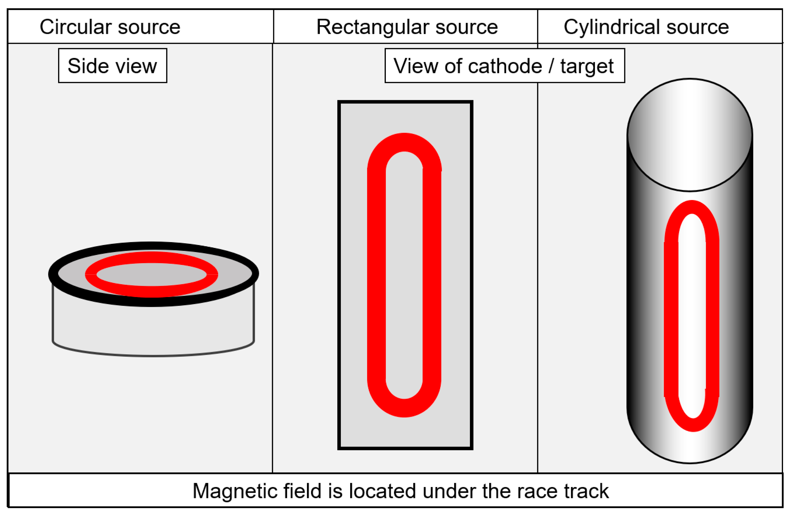
Table 1.
Maximum Al content for pure fcc phase generation measured by X-ray diffraction for arc-deposited and sputtered coatings.
Table 1.
Maximum Al content for pure fcc phase generation measured by X-ray diffraction for arc-deposited and sputtered coatings.
| Deposition Method | Source Composition (Targets/Cathodes) | Pure fcc Phases by X-Ray at Al [at.%] Coating or Source | Fcc + hcp Phases by X-Ray at Al [at.%] Coating or Source | Range of Transition Almax [at.%] | Reference |
|---|---|---|---|---|---|
| RF sputtering | Al and Cr targets | Coating 57 at RT 56 at 300 °C | Coating 75 at RT 67 at 300 °C | Coating 57 < Almax < 67 | [49] |
| RF/DC sputtering | Al and Cr targets | Coating 63 at 300 °C | - | 63 < Almax | [51] |
| Pulsed CFUBM sputtering | Al and Cr targets | Coating 60.9 at 175 °C | Coating 64 at 175 °C | Coating 60.9 < Almax < 64 | [59] |
| Arc | Alloyed cathodes | Cathodes 60 at 600 °C | Cathodes 70 at 600 °C | Cathodes 60 < Almax < 70 | [60] |
| Arc | Alloyed cathodes | Coating 70 at 500 °C TEM traces hcp | - | Coating 70 < Almax | [62] |
| Arc | Alloyed cathodes | Coating 71 at 450 °C | Coating 75 at 450 °C | Coating 71 < Almax < 83 | [61] |
| Arc | Alloyed cathodes | Coating 71 at 450 °C | Coating 75 at 450 °C | Coating 71 < Almax < 75 | [63] |
| DC sputtering | Segmented target | Coating 70 at 400 °C | - | Coating 70 < Almax | [64] |
| DC sputtering | Alloyed targets | Targets 1 70 at 500 °C | - | Targets 70 < Almax | [65] |
| Arc | Alloyed cathodes | Coating 70 at 500 °C | Coating 82 at 500 °C | Coating 70 < Almax < 82 | [66] |
1 source: no measurement of chemical composition in the coating, values from cathodes/targets.
Table 2.
Selected coatings alloyed with one metal and metalloid component.
| Alloying Element | Coating Composition | Cathodes/Targets | Deposition Method | Results | Reference |
|---|---|---|---|---|---|
| Ti | e.g., Al30.5Cr14 Ti5.5N50 | Al66Ti29Cr5, Al67Cr33, Al34Cr33, Al67Ti33 | Arc/ different AlCrTi composition in one batch | Age hardening | [97] |
| (Al66Cr24Ti10)N | Al70Cr20Ti10 | Arc | Age hardening | [98] | |
| e.g., (Al69Cr20Ti11)N | Al65Cr21Ti14, Al71Cr19Ti10, Al74Cr18Ti8 | Arc | Oxidation onset 1000 °C | [99] | |
| V | Al25Cr22V3N50 | Al55Cr45, Al55Cr40V5 | Arc | Higher hardness, reduced oxidation onset | [100] |
| e.g., Al34Cr10.5V5.5N50 | Al70Cr30–xVx; x = 0, 10, 15, 20, 25, and 30 | Arc | Metastable solubility limit decreases at low bias | [101] | |
| Cr29.5Al10.5V10N50 | Al80Cr20 Cr80Al insert targets, and Cr, V | DC sputter Plus HiPIMS | Lower friction (Magnéli phases) | [102] | |
| (AlCrV)N | Al70Cr30, Cr70V30 | Arc | Cutting test hardness, structure | [103] | |
| Zr | Cr38.8Al4.5V2N54.8 | Al90Cr10, Al80Cr20, and Cr, Al, Zr | DC sputter | Lower friction and wear | [104] |
| Mo | e.g., Cr20Al18.5 Mo7N54.5 | Al60Cr40, Al70Cr30, Al55Mo45, with inserts Mo,Cr,Al60Cr40, Al85Cr15 | DC sputter | H/E optimisation | [105] |
| e.g., (Al50Cr37 Mo13)N | Cr35Al65, and Cr, Mo | Arc | Triboactive, element Mo | [106] | |
| (AlCrMo)N | Al70Cr30, Cr70Mo30 | Arc | Cutting test hardness, structure | [103] | |
| Hf | e.g., Al37Cr11Hf2N50 | AlCr20 (Cr in Al) inserted, and Hf | DC sputter | Higher oxidation resistance | [107] |
| Nb | e.g., Al27.5Cr17.5Nb5N50 | Al55Cr45, Al60Cr35Nb5, Al60Cr30Nb10 | Arc | Higher hardness, lower oxidation resistance | [108] |
| W | e.g., (Al64Cr31W5)N | Al70Cr30, Al70Cr25W5 | Arc | Improved oxidation resistance at 1100 °C | [81] |
| Cu | e.g., (Al47Cr34Cu19)N | Cr35Al65, and Cr, Cu | DC sputter | Triboactive, hardness decrease | [106] |
| Y | e.g., Al26.5Cr22.5Y1N50 | Al/Cr = 1.5 with 0, 2, 4, 8 at.% Y | DC sputter | Structure, improved oxidation resistance | [109,110] |
| e.g., Al23.8Cr23.1Y0.7N50O2.4 | Al50Cr50, Y | DC sputter | Improved oxidation | [111] | |
| e.g., Cr25.8Al15.3Y3.4N55.5 | Al90Cr10, Al80Cr20, and Y | DC sputter | Structure, improved oxidation | [112] | |
| La | e.g., Al28.1Cr12.5La1.4N58 | Al70Cr30, and La | DC sputter | Wear, friction, structure | [113] |
| C | e.g., Cr44.4Al12C27.6N16 | Cr2AlC | DC sputter | Wear, friction, structure | [114] |
| e.g., Cr24Al24N48C4 | AlCr20, AlCr24, Cr inserts in Al, and Cr | DC sputter HiPIMS | Structure, hardness | [115] | |
| B | e.g., Al26.7Cr21.7B2.3N49.3 | Al60Cr40, Al70Cr30, B alloyed Al/Cr =1.8, with 10, 20, 30 at.% | Arc | Structure, phases, hardness, nano composite | [89] |
| e.g., Al30.4Cr16.3B2.1N48.1O3.1 | Al55Cr35B10, Al70Cr30 | Arc | Structure, wear, tribology | [58] | |
| e.g., (Al64.5Cr32.9B2.6)N | Al70Cr30, Al70Cr25B5, | DC sputter | Oxidation, structure | [81] | |
| Si | See Section 4.4 paragraph Cr-Al-Si N and Al-Cr-Si-N | ||||
Table 3.
Brief characteristics of selected industrially applied AlCrN-based coating types.
| Feature | Monolayer Arc (e.g., BALINIT® ALCRONA PRO) | Multilayer (e.g., BALINIT® HELICA) | Monolayer Sputtering (e.g., BALIQ® ALCRONOS) |
|---|---|---|---|
| Source type | Magnetic steered arc | Magnetic steered arc | Magnetron optimised for S3p (HiPIMS) |
| Cathode type/form | Powder metallurgical/circular | Powder metallurgical and vacuum melting/circular | Powder metallurgical/circular |
| Coating temp. [°C] | 400–500 °C | 400–500 °C | 400–500 °C |
| Chemical composition | Al > Cr content at.%
|
| Al > Cr content at.%
|
| Alloying types |
| - |
|
| Coating hardness/Indentation E-modul range [GPa] | 29–37 390–420 | 32–39 380–410 | 31–38 370–430 |
| Thickness [um] | 0.5–6 | 1–4 | 0.5–5 |
| Speciality | Universal use | High hardness | Low defect density, smooth |
Publisher’s Note: MDPI stays neutral with regard to jurisdictional claims in published maps and institutional affiliations. |
© 2021 by the authors. Licensee MDPI, Basel, Switzerland. This article is an open access article distributed under the terms and conditions of the Creative Commons Attribution (CC BY) license (http://creativecommons.org/licenses/by/4.0/).
Share and Cite
MDPI and ACS Style
Vetter, J.; Eriksson, A.O.; Reiter, A.; Derflinger, V.; Kalss, W. Quo Vadis: AlCr-Based Coatings in Industrial Applications. Coatings 2021, 11, 344. https://0-doi-org.brum.beds.ac.uk/10.3390/coatings11030344
AMA Style
Vetter J, Eriksson AO, Reiter A, Derflinger V, Kalss W. Quo Vadis: AlCr-Based Coatings in Industrial Applications. Coatings. 2021; 11(3):344. https://0-doi-org.brum.beds.ac.uk/10.3390/coatings11030344
Chicago/Turabian StyleVetter, Joerg, Anders O. Eriksson, Andreas Reiter, Volker Derflinger, and Wolfgang Kalss. 2021. "Quo Vadis: AlCr-Based Coatings in Industrial Applications" Coatings 11, no. 3: 344. https://0-doi-org.brum.beds.ac.uk/10.3390/coatings11030344
Note that from the first issue of 2016, this journal uses article numbers instead of page numbers. See further details here.