Article

Spacing Ratio Effects on the Evolution of the Flow Structure of Two Tandem Circular Cylinders in Proximity to a Wall

1
School of Science, Shanghai Institute of Technology, Shanghai 201418, China
2
School of Mechanical Engineering, Shanghai Institute of Technology, Shanghai 201418, China
3
Shanghai Institute of Applied Mathematics and Mechanics, School of Mechanics and Engineering Science, Shanghai University, Shanghai 200072, China
4
College of Urban Construction and Safety Engineering, Shanghai Institute of Technology, Shanghai 201418, China
*
Author to whom correspondence should be addressed.
J. Mar. Sci. Eng. 2024, 12(5), 721; https://0-doi-org.brum.beds.ac.uk/10.3390/jmse12050721
Submission received: 20 February 2024 / Revised: 11 April 2024 / Accepted: 16 April 2024 / Published: 26 April 2024
(This article belongs to the Section Ocean Engineering)

Abstract

:
The flow around two tandem circular cylinders in proximity to a wall is investigated using particle image velocimetry (PIV) for Re = 2 × 10³. The spacing ratios L/D are 1, 2, and 5, and the gap ratios G/D are 0.3, 0.6, and 1. The proper orthogonal decomposition (POD) method and λ c i vortex identification method are used to investigate the evolution of flow structure, and the influences of L/D and G/D on flow physics are shown. At L/D = 2 and G/D = 0.3, a “pairing” process occurs between the wall shear layer and the upstream cylinder’s lower shear layer, resulting in a small separation bubble behind the upstream cylinder. At L/D = 1, the Strouhal number (St) increases with decreasing G/D. At three gap ratios, the St gradually decreases as L/D increases. At G/D = 0.3, there is nearly a 49.98% decrease from St = 0.3295 at L/D = 1 to St = 0.1648 at L/D = 5, which is larger than the reductions in cases of G/D = 0.6 and G/D = 1. The effects of L/D on the evolution of flow structure at G/D = 0.6 are revealed in detail. At L/D = 1, the vortex shedding resembles that of the single cylinder. As L/D increases to 2, a squarish flow structure is formed between two cylinders, and a small secondary vortex is formed due to induction of the lower shear layer of the upstream cylinder. At L/D = 5, there is a vortex merging process between the upper wake vortices of the upstream and downstream cylinders, and the lower wake vortex of the upstream cylinder directly impinges the downstream cylinder. In addition, the shear layers and wake vortices of the upstream cylinder interact with the wake of the downstream cylinder as L / D increases, resulting in reductions in velocity fluctuations, and the production and turbulent diffusion of turbulent kinetic energy are decreased behind the downstream cylinder.

1. Introduction

Multiple cylinders in interaction with each other are frequently seen in engineering applications; for example, in submarine cables and submarine oil pipelines [1,2,3,4,5,6]. Investigating the flow of water past two tandem cylinders, as a typical model of multiple cylinders, is helpful for understanding the evolution of wake flow [7,8,9]. When the two cylinders are positioned near a wall, which is a common situation in ocean engineering, the wall shear layer interacts with the cylinder wake, and the interaction makes the flow more complex [8,10]. Therefore, investigations of wake characteristics and the evolution of flow structures should be further conducted.
The flow regimes of two tandem cylinders have been widely investigated in previous studies. Flow regimes were subdivided into three typical regimes by Zdravkovich [11], which were, respectively, called the “extended-body”, “re-attachment”, and “co-shedding” regimes by Zhou and Yiu [12] and Xu and Zhou [13], and described as follows: (i) For small spacing ratios L / D , where L was the streamwise length between the centers of two cylinders and D is cylinder diameter, two circular cylinders were positioned closely together with small horizontal spacing ratios, making them resemble a single structure; (ii) For moderate L / D , the upstream cylinder’s shear layers could reattach to the downstream one’s surface; (iii) For large L / D , the vortex streets are formed behind two cylinders. Therefore, the flow pattern of two tandem cylinders was significantly influenced by L / D . Additionally, Zhou et al. [14] investigated the flow of the two cylinders at various   L / D using large eddy simulations (LES) at R e = 1 × 10 3 , and the Strouhal number ( S t ) was significantly influenced by L / D . Lin et al. [15] conducted an experiment with R e = 1 × 10 4 and L / D = 1.15 5.1 , and they found that L / D affected the distributions of Reynolds stresses. The flow behavior of two tandem cylinders was influenced by the Reynolds number [16,17,18,19]. Many experimental results have demonstrated the significant impact of the Reynolds number on flow [9,13,16]. In the review of Sumner [20], when the “reattachment” regimes changed to the “co-shedding” regimes, there was an existence of the critical spacing ratio ( L / D ) c , which was significantly influenced by R e . Alam [21] experimentally investigated the effects of R e on Reynolds stresses at R e = 9.7 × 10 3 6.5 × 10 4 .
In recent years, the flow around two tandem cylinders placed near a wall has received more attention, as outlined in Table 1. The influence of G / D on flow characteristics were investigated in some numerical studies with a low Reynolds number, where the gap size between the wall and the lower surface of two cylinders was G . Harichandan and Roy [22] numerically found that the interaction between the cylinder wake and the wall was much weaker than that of a single cylinder at R e = 1 × 10 2 and 2 × 10 2 . The numerical simulations study of Rao et al. [23] investigated flow stability and flow dynamics when the tandem cylinders slid along the wall at 20 R e 2 × 10 2 . The similar study was reported by D S‘ouza et al. [24] at R e = 2 × 10 2 . Tang et al. [25] observed that wake vortex shedding was completely suppressed when G / D was very small at R e = 2 × 10 2 .
Some studies have examined the flow structures of two tandem cylinders at high Reynolds numbers. At R e = 6.3 × 10 3 , Wang et al. [8] used PIV to determine the hydrodynamic forces, Strouhal number and Reynolds shear stress. Li et al. [2] numerically observed that the streamwise vortices between two cylinders became stronger as G / D decreased at R e = 1.31 × 10 4 . Prsic et al. [3] found that the flow past tandem cylinders exhibited a wide gap regime at G / D = 1 , and its interaction with the wall was stronger at G / D = 0.6 . Hu et al. [9] numerically researched the effects of L / D on the scouring process around two tandem pipelines for different R e .
The existing studies have shown that the flow characteristics past two tandem cylinders are significantly affected by L / D . In ocean engineering, when the tandem marine pipelines are positioned near a wall, the interaction between the wakes of two tandem pipelines and the boundary layer flow results in complex flow characteristics and pipeline behavior. Therefore, investigations of the flow of two tandem cylinders placed near a wall are essential. There are few experimental studies on the flow characteristics of two tandem cylinders placed near a wall, and PIV experiments are necessary for expanding the database. The experimental results can be compared with other numerical results to enrich the investigations of flow past two near-wall tandem cylinders. What is more, the effects of G / D and L / D on wake characteristics should be investigated further, and the evolution of flow structure should be examined in detail. Motivated by these knowledge gaps, the objective of this study is to investigate the effects of L / D on the evolution of the flow structure of two near-wall tandem cylinders by PIV experiments at a middle Reynolds number of R e = 2 × 10 3 , and the interaction between the wall boundary layer and the wakes of the two tandem cylinders is examined. The present study can improve the understanding of the interaction between wall boundary layers and the multiple cylinder wakes, which is helpful for developing optimal control methods for marine pipelines.
In this paper, Section 2 presents the data processing methods and experimental setup. Section 3 presents the results and analysis, including mean flow physics, vortex shedding, evolution of flow structure, Reynolds stresses, and turbulent transport. Lastly, Section 4 provides the principal concluding remarks.

2. Experiment and Data Processing Method

2.1. Experiment Model and Measurement

Experiments are performed in the low-speed circulating water channel, and the sizes of the test sections are 400   m m × 300   m m × 6000   m m (height × width × length), as shown in Figure 1. The previous work of Liu et al. [10] provides a more detailed description of the experimental channel. A 2000   m m × 280   m m × 15   m m (length × width × thickness) smooth flat plate is placed in the channel’s test section, with a beveled cut at the plate’s leading edge to minimize the effects of flow separation. The height H1 from the water surface to the flat plate is 270 mm, and the vertical height H2 from the bottom of the channel to the flat plate is 35 mm. The experimental incoming flow velocity remains constant at U = 0.132 m/s, with the turbulence intensity of the free stream below 2.5 % . In the absence of cylinders, a laminar boundary layer develops along the planar boundary, and its thickness δ is about 11.4 mm ( δ / D = 0.76 ).
The two tandem cylinders are fixed by rectangular end plates with dimensions 150   m m × 5   m m × 150   m m (width × thickness × length) in the experiments. Two tandem cylinders are positioned parallel to each other and placed horizontally above the plate, as seen in Figure 1. The diameter D of two tandem cylinders is 15 mm, the length W of the cylinders is 275   m m , and the ratio of the cylinder length to the cylinder diameter is W / D = 18.3 , which can ensure obvious two-dimensional flow characteristics at the center section of cylinder. Meanwhile, the streamwise length between the upstream cylinder’s center to the plate’s leading edge is L n = 300 mm, and L n / D = 20 , which reduces the flow separation of the leading edge. The normal length between the cylinder’s lower surface and the plate is denoted as G , and the streamwise length between the centers of the two cylinders is expressed as L . In the present expreriments, G / D = 0.3 , 0.6, and 1, and L / D = 1 , 2, and 5. The kinematic viscosity of water is ν = 0.9599 × 10 6 m2/s when the temperature of the water is about 22   , and the Reynolds number is R e = U D / ν = 2 × 10 3 . The coordinates x and y represent the streamwise direction and vertical direction, respectively.
Since the experimental setup is analogous to that used in Liu et al. [10], this section provides only essential information. The experiments are conducted by time-resolved particle image velocimetry (TRPIV) equipment supplied by LaVision Inc. (Gottingen, Germany). The sizes of the PIV fields of view are 180   m m × 120   m m   ( 12 D × 8 D ) , and the PIV region is perpendicular to the flat plate and located at the center section of the cylinder. Polyamide resin particles, with an average diameter of 20 µ m and an average density of 1.03 g / c m 3 , are released in the test area and circulated for mixing in the channel. The flow field can be illuminated by the double-pulsed laser, as shown in Figure 1, and the images are obtained by Phantom M 110   C C D camera ( A F Nikkor 50 mm lens, f / 1.4 ) at a resolution of 1280   p i x e l s × 800   p i x e l s . For each experimental condition, 2000 pairs of PIV images are acquired at a 100 Hz sampling frequency, yielding 2000 sets of instantaneous flow fields, which is sufficient for statistical convergence. The experimental data are processed using the D a V i s 8.3 software, and a multi-channel interrogation algorithm is applied [10]. The final interrogation window size is 32   p i x e l s × 32   p i x e l s with 75 % overlap, and the distance to neighboring velocity vectors is about 1.1 mm, which corresponds to 0.073 D , and 100 × 160 velocity vectors are obtained for each case.
The characteristics of the flat plate boundary layer are investigated to validate the accuracy of the PIV setup. The profiles of the streamwise velocities are presented in Figure 2, which is the function of η = y U / ν X , where X is the flow direction length from the selected position to the flat plate’s leading edge, expressed by X = L n + x . The profiles of the velocity for three streamwise locations closely match the Blasius solution, suggesting that the laminar boundary layer is developed in the PIV test region. Based on U y / U = 0.99 , the thickness δ of the wall boundary layer at x / D = 0 is 11.4 mm ( δ / D = 0.76 ). In addition, the vortex shedding frequencies of two tandem cylinders without the influence of the wall at L / D = 3 are studied. Figure 3 shows the S t of the downstream cylinder, and the value of S t = 0.1679 resembles the result of Xu and Zhou [13] at L / D = 3 and R e = 2 × 10 3 . Therefore, the accuracy of the PIV experiment is validated.

2.2. Uncertainty of Time-Averaged Velocity

This section carries out the analysis of time-averaged velocity uncertainty. According to the study of Sciacchitano and Wieneke [26], the streamwise time-averaged velocity uncertainty is obtained as
ε U ¯ = σ u N
where N denotes sample size, and σ u represents the standard deviation of streamwise velocity. Moreover, the latter comprises two elements: the actual velocity fluctuation and the errors of measurement. Since the errors of measurement are significantly smaller than the actual velocity fluctuation, it is neglected here [27]. The N and the maximum σ u are substituted into each individual case in the study, and then the uncertainty of U ¯ can be anticipated to be less than 0.98 % of U .

2.3. Data Processing Method

Firstly, the method of proper orthogonal decomposition (POD) is introduced briefly. POD is an effective method to capture coherent structures [28,29], and the fluctuating velocity u breaks up into the time component a n and the POD modes Φ n , which is expressed by
u = n = 1 N a n Φ n ,
where N is the sample size in the POD analysis. The proportion of turbulent kinetic energies contained by the first few POD modes of the total turbulent energy is obtained by E i = λ i / n = 1 N λ n , where λ i is the eigenvalue and represents the turbulent kinetic energy contained by each POD mode. The first few POD modes represent more turbulent energy, which can reflect the large-scale dynamics of the flow. Based on previous studies [30,31], the first few POD modes are selected to reconstruct the instantaneous velocity field to study the development and evolution of large-scale flow structures. The POD reconstruction is expressed by
u U ¯ + i = 1 N a i φ i
where U ¯ is time-averaged velocity.
Secondly, the vortex identification method λ c i is applied to capture vortical structures [32]. To capture the swirling strength and rotation sense of vortices, the Λ c i field can be obtained by Λ c i = λ c i · ω z / ω z where ω z is spanwise vorticity expressed by ω z = v / x u / y . Other vortex identification methods were also reported in the previous studies [33,34,35]. In the present study, the λ c i method is used to identify the wake vortices and the secondary vortex, which is helpful for investigating the evolution of flow structures [31,36,37].
Finally, the turbulent transport is investigated by the transport equation of turbulent kinetic energy. In this study, we are mainly concerned with the turbulent transports of the x-y plane using the transport equation of turbulent kinetic energy [38,39]. Thus, the equation can be expressed as
k t + u ¯ j k x j = u i u j ¯ u ¯ i x j 1 ρ ( p u j ) ¯ x j ( 0.5 u i u i u j ) ¯ x j + v 2 k x j x j v u i x j u i x j ¯
where the left side of the formula is the mean convection. On the right side of the formula, the items from left to right are production item, pressure diffusion, turbulent diffusion, viscous diffusion, and dissipation, respectively. In the present study, turbulent kinetic energy k , the production item P , and the turbulent diffusion T are analysed. The turbulent kinetic energy is expressed as k = 0.5 ( u u ¯ + v v ¯ ) .

3. Results and Discussion

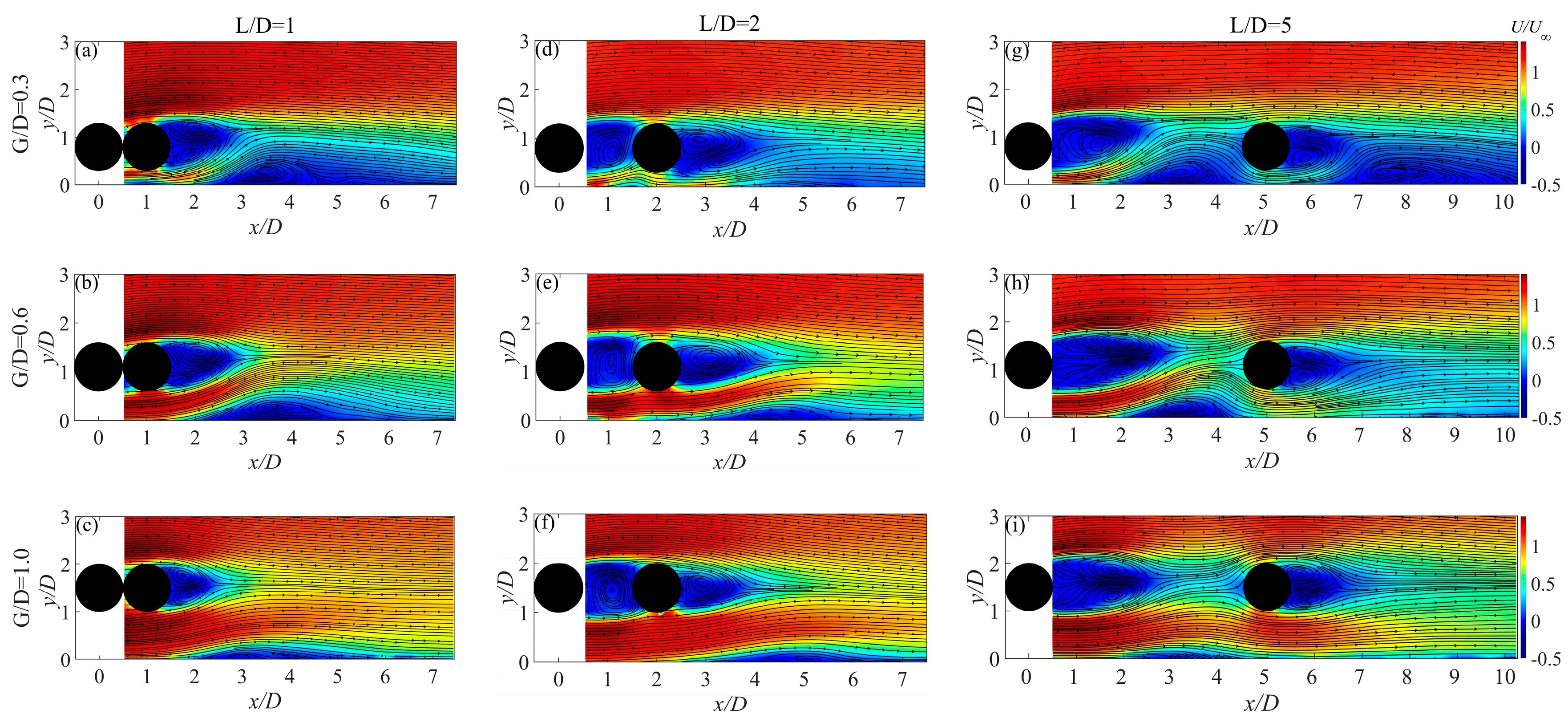
3.1. Mean Flow Physics

The L/D and G/D can influence the average flow field, and Figure 4 illustrates the distributions of mean streamwise velocity. The situation in Figure 4a–c (L/D = 1) is referred to as the flow regime of the “extended-body”, where the two tandem cylinders are close together so that the cylinders appear to be a single blunt body. From this perspective, only one recirculation region and a separation bubble on the wall behind the downstream cylinder are observed. By comparing the flow fields with changing G/D, it is observed that when the cylinders gradually approach the wall, the recirculation area behind the downstream cylinder deflects upward, and the size of the separation bubbles also becomes larger with decreasing G/D, which is similar to the result of He et al. [40] and Zhou et al. [41].
For moderate L/D, as illustrated in Figure 4d–f, where L/D = 2, the flow becomes a “re-attached” regime. The area between the two cylinders is occupied by the upstream cylinder’s wake, forming a recirculation zone. This phenomenon reflects that the downstream cylinder can interfere with the wake of the upstream cylinder. A cavity-like squarish flow structure forms between the two cylinders, causing the flow between two cylinders to circulate in the cavity all the time, and this finding is consistent with the result of Li et al. [2]. As illustrated in Figure 4d, a small separated bubble appears on the wall between two cylinders. There is no separation bubble near the wall behind the downstream cylinder. Instead, a low-velocity region is formed with a significant streamwise extent. When G/D increases from 0.6 to 1, the small separation bubble behind the upstream cylinder gradually disappears. Instead, the gap flow passes underneath the downstream cylinder, and it deflects upwards and finally forms a separation bubble near the wall.
As shown in Figure 4g–i, for large L/D, where L/D = 5, the case is a “co-shedding” regime, where L/D is larger so that a complete vortex shedding process occurs on each cylinder. For an extremely narrow gap, i.e., as illustrated in Figure 4g at G/D = 0.3, a separated bubble forms on the wall behind each of the two tandem cylinders. The separation bubble of the upstream cylinder is located just ahead of the downstream one, causing a decreasing gap flow under the downstream cylinder. The second separation bubble forms on the wall. When G/D increases, the blockage effect gradually weakens. As evidence, in Figure 4h,i, the intensity of the gap flow gradually increases, and no separation bubble forms on the wall behind the upstream cylinder. Furthermore, at G/D = 1.0, as illustrated in Figure 4i, the size of the separated bubbles is very small and the recirculation areas behind the two cylinders are relatively symmetrical.
The impact of the spacing ratio and gap ratio on the average flow is also evident in the distribution of mean spanwise vorticity, defined as ω z = ω z D / U as illustrated in Figure 5. It is observed that when G/D decreases, the lower shear layer originating from two cylinders will deflect upwards due to the normal pressure gradient, while the impact of the wall on the upper shear layer is relatively small. At L/D = 1, the shear layer is very similar to that of single near-wall cylinder. In a very small gap ratio, specifically G/D = 0.3 in Figure 5a, the wall shear layer develops and extends below the two cylinders. However, at G/D = 0.6, the starting position of this shear layer is located on the wall below the downstream cylinder in Figure 5b. These two gap ratios exhibit a very clear “pairing” phenomenon, which is weakened at G/D = 1.0.
When L/D expands to 2, the upstream cylinder wake is influenced by the downstream cylinder. This is due to the fact that the shear layer forms from the upstream cylinder and is attached to the downstream cylinder. At G/D = 0.3, as illustrated in Figure 5d, the wall shear layer below the upstream cylinder has strong vorticities, while no concentrated vorticities can be observed on the wall below the downstream cylinder. This phenomenon is associated with the weak gap flow below the downstream cylinder. In Figure 5e, when G/D = 0.6, a “pairing” phenomenon occurs between the wall shear layer and the lower shear layers of the two tandem cylinders. In the flow field, this manifests as a continuous shear layer that extends from below the upstream cylinder to behind the downstream one. When G/D = 1.0, the starting position of the wall shear layer is below the downstream cylinder, indicating that a strong gap flow is formed.
When L/D = 5, there are complete shear layers behind both cylinders, but the downstream cylinder’s shear layers are shorter than those of the upstream cylinder. This difference is related to the distinct shedding frequencies of the two cylinders. In Figure 5g,h, the shear layer only appears on the wall behind the cylinder, indicating that the velocity shear steepness near the wall behind the downstream cylinder is weak when G/D = 0.3 and 0.6. In the case where G/D = 1.0, intermittent shear strips exist on the wall. At this point, the wakes of both cylinders interact with the shear layer of wall.

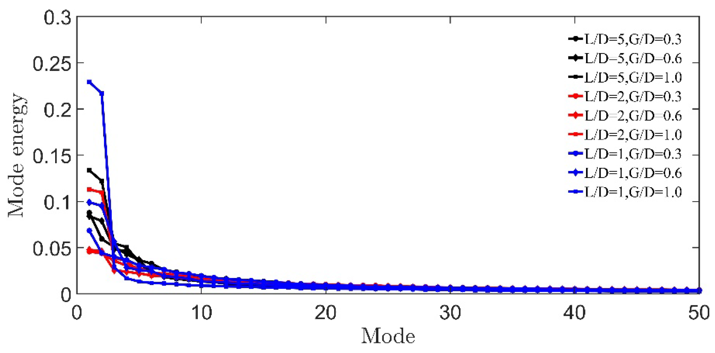
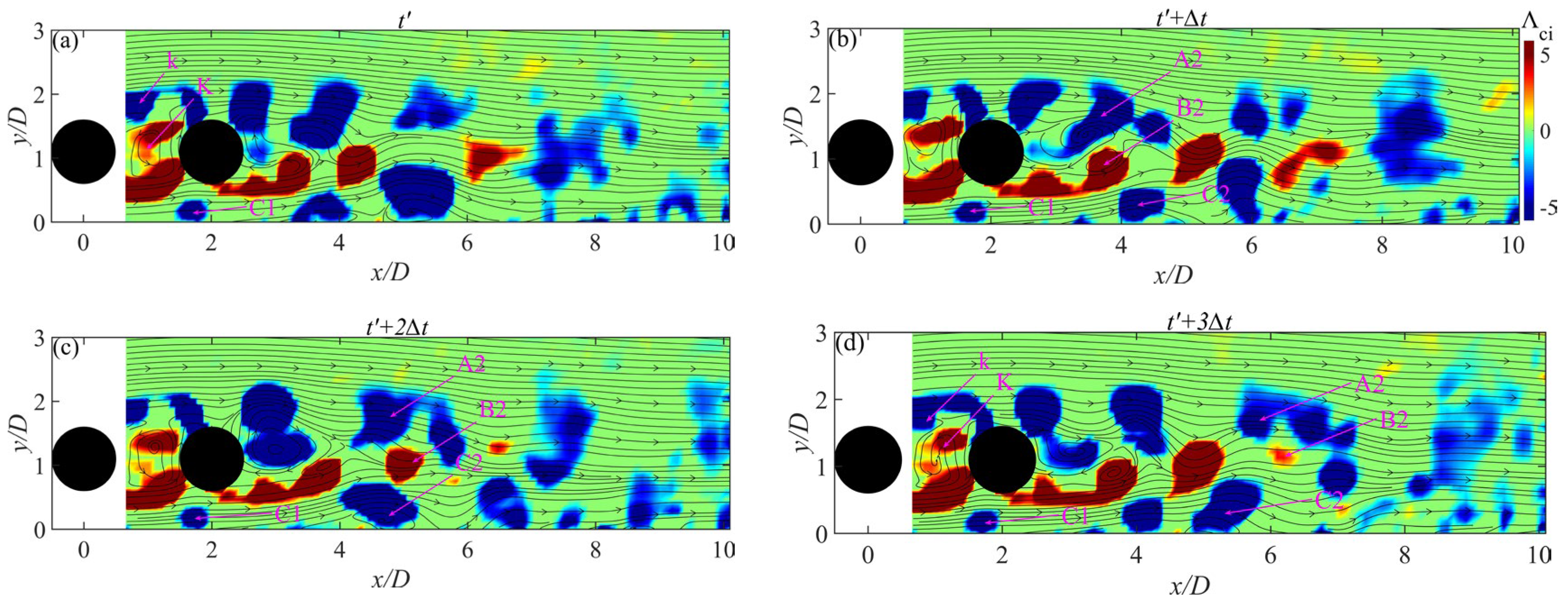
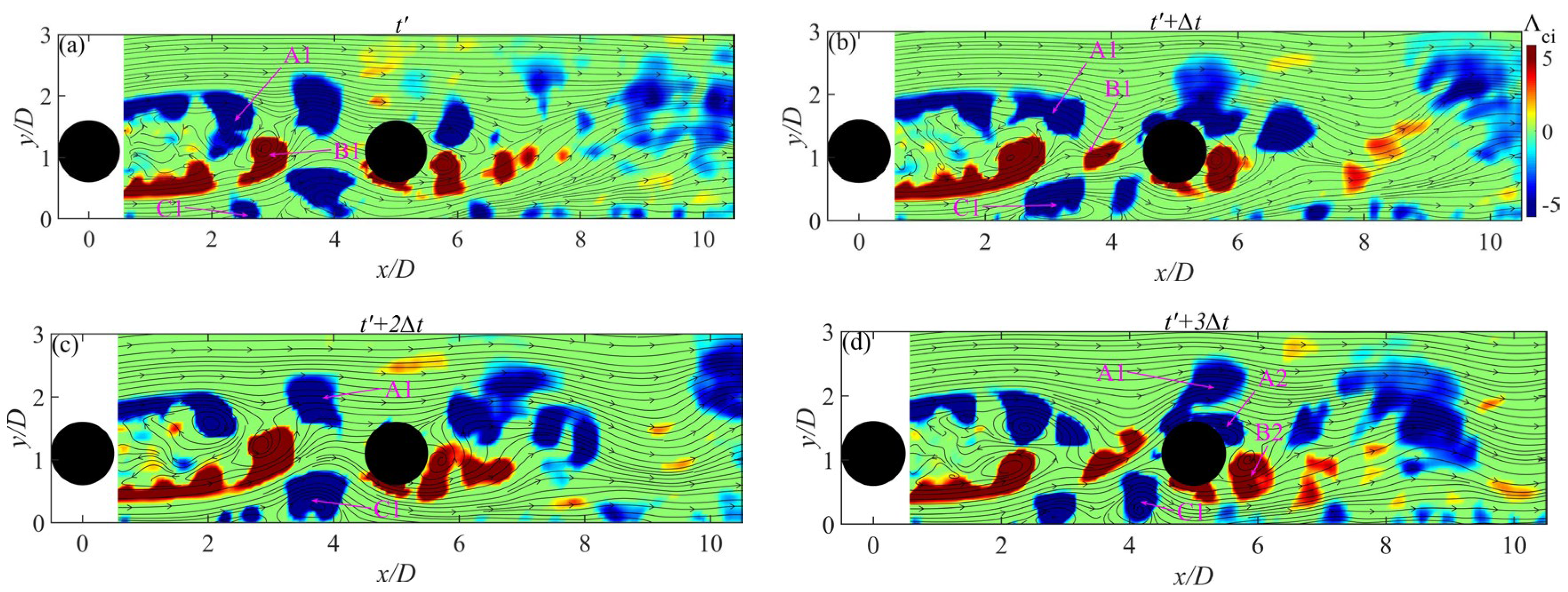
3.2. Evolution of Flow Structure

To further investigate the influence of L / D and G / D on the wake vortex shedding and the evolution of the flow structure in the experimental study, we use the analysis of power spectral density to examine the vortex shedding frequencies, and POD analysis and vortex identification method λ c i are applied to identify vortex evolution in this section.

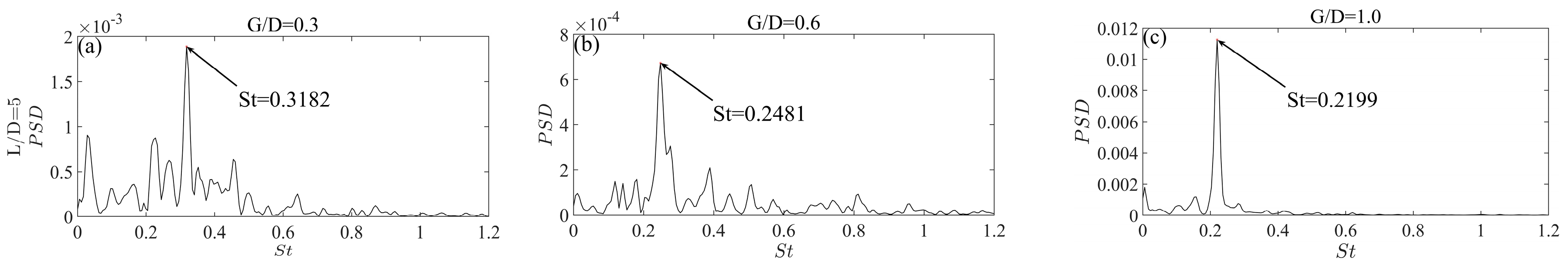
3.2.1. Vortex Shedding Characteristic

Figure 6 illustrates power spectral density (PSD) distributions of vertical fluctuation velocity ν in the wake region of the downstream cylinder. In the PSD analysis of normal fluctuation velocity, the value of the downstream cylinder’s wake vortex shedding frequencies can be seen at the peak of the PSD. In order to accurately capture the wake vortex shedding frequencies, the study conducts spectral analysis based on the curl locations of the downstream cylinder’s shear layers in the time-averaged spanwise vorticity distributions of Figure 5. Therefore, some velocity traces of the wall-normal and streamwise locations of the selection are shown as follows: For L / D = 1 (a) the streamwise position x / D = 2.58 and the normal position y / D = 1.31 at G / D = 0.3 ; (b) x / D = 2.58 and y / D = 1.011 at G / D = 0.6 ; (c) x / D = 1.84 and y / D = 1.16 at G / D = 1.0 . For L / D = 2 : (d) x / D = 3.87 and y / D = 1.36 at G / D = 0.3 ; (e) x / D = 3.42 and y / D = 1.09 at G / D = 0.6 ; and (f) x / D = 2.90 and y / D = 1.82 at G / D = 1.0 . For L / D = 5 (g) x / D = 6.29 and y / D = 1.47 at G / D = 0.3 ; (h) x / D = 5.68 and y / D = 1.72 at G / D = 0.6 ; and (i) x / D = 5.75 and y / D = 1.94 at G / D = 1.0 .
The vortex shedding of the downstream cylinder is studied firstly. When L/D = 1, the two tandem circular cylinders are so very close that the flow field passing through the two cylinders resembles that of the flow passing through the single near-wall cylinder. This is why the flow regime is referred to as an “extended body”. Figure 6a–c shows that the vortex shedding frequency increases as G/D decreases, which is in line with the findings of Price et al. [42] and Zhou et al. [43]. The monotonic change pattern of the vortex shedding frequency is no longer valid at L/D = 2, i.e., in a “re-attachment” regime, as can be observed from Figure 6d–f. As G/D decreases from 1.0 to 0.6, the S t increases from 0.2216 to 0.2989. When G/D decreases to 0.3, the S t decreases to 0.2273. The similar trend of S t is also observed at L/D = 5 in Figure 6g–i; it initially increases from 0.2199 to 0.2481 as G/D decreases from 1.0 to 0.6, and then decreases to 0.1648 at G/D = 0.3. The non-monotonic trend of S t is attributed to the upstream cylinder wake interference, and the shear layer and wake vortices of the upstream cylinder interact with the downstream cylinder, which affects the process of vortex shedding of the latter.
Secondly, the vortex shedding of the upstream cylinder is studied. For L/D = 1, the wake vortices are formed from the downstream cylinder. For L/D = 2, the vortices are mainly shedfrom the downstream cylinder. For L/D = 5, the vortex shedding frequencies of two cylinders are different, which will be discussed. To further investigate the vortex shedding frequencies of the upstream cylinder, the power spectral density of the vertical fluctuating velocity ( ν ) in the wake region of the upstream cylinder for L / D = 5 is shown in Figure 7a–c. The velocity traces are given as (a) x / D = 1.92 and y / D = 1.63 at G / D = 0.3 ; (b) x / D = 2.56 and y / D = 1.72 at G / D = 0.6 ; and (c) x / D = 2.44 and y / D = 1.94 at G / D = 1.0 . In Figure 7a, at G / D = 0.3 , the S t of the upstream cylinder is bigger than that of the downstream cylinder. This is due to the effects of the gap flow below the two cylinders. For the upstream cylinder at G / D = 0.3 , the gap flow is strong and it deflects and interacts with the cylinder shear layers, resulting in an increase in the vortex shedding frequency. However, for the downstream cylinder at G / D = 0.3 , the gap flow becomes weaker, the vortex shedding is suppressed slightly by the wall, and the vortex shedding frequency is decreased. At G / D = 0.6 and G / D = 1 , the S t of the upstream cylinder is the same as that of the downstream cylinder, reflecting the characteristics of the “co-shedding” regime, and this is consistent with the results of Ljungkrona and Sundén [18].
Figure 8 illustrates the relationship between the S t of the downstream cylinder and the spacing ratio at various gaps. The figure also presents the results of previous studies at different Re [8,37]. Due to differences in the Reynolds numbers and boundary layer thicknesses between the present study and the previous studies, there is deviation in the variation of S t . The present results enrich the investigations of vortex shedding frequency in flow past two tandem cylinders in proximity to a wall. At three G/D in present experiments, the S t decreases with increasing L/D. This fact might indicate that the impinging of the wake of the upstream cylinder on the downstream cylinder becomes weaker as L/D increases from 2 to 5, which leads to a decrease in S t . For L/D = 1, the increase in S t at small G/D is mainly caused by the effects of deflected gap flow. For L/D = 2 and L/D = 5, as G/D decreases from 1 to 0.3, the S t presents a trend of first increasing and then decreasing. The reasons for the variation in S t will be discussed later.

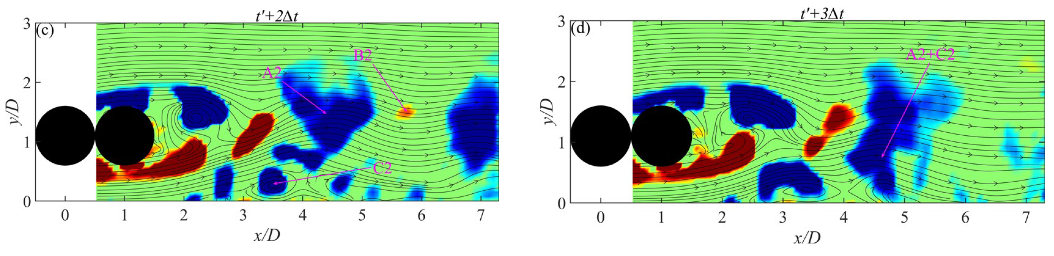
3.2.2. Evolution Process of Flow Structure

In order to study the evolution and interaction processes of vortices, the POD method can reconstruct the instantaneous flow field, and the vortex structures in the flow field are identified using the λ c i method. As a modal decomposition method based on turbulent energy [28,30], the approach can effectively capture flow structures. For each situation, this study selected 2000 snapshots of instantaneous flow fields for POD analysis. As typical situations for vortex evolution, the flow field under the conditions of L / D = 1, 2, and 5, and G / D = 0.6 is reconstructed using the POD method, as expressed by Equation (3).
Existing studies have shown that modal reconstruction of over 50% of the energy is enough to capture the large-scale flow structures, which reproduce the evolution of the flow field and reduce the influences of small-scale flow fluctuations [43,44]. Figure 9 displays the modal energy distributions for each situation. It can be observed that the first 50 modes already represent the majority of turbulent fluctuating energy. Based on the distribution of modes in different situations in Figure 9, this study chooses the appropriate range of POD modes. Specifically, the POD modes which carried 50% of total turbulent energy are selected to reconstruct the instantaneous velocity field; therefore, 22 , 32 , and 22 orders of POD modes are chosen for L / D = 1 , 2, and 5, respectively.
According to the reconstructed velocity fields, the Λ c i field is obtained to study vortex evolution. In order to identify important vortex structures, we use notations to represent them. For example, in the following context, A1 and B1 represent the shedding vortices of the upstream cylinder, while A2 and B2 represent those shed from the downstream cylinder. C1 and C2 represent the secondary vortices induced by B1 and B2, respectively. Four instantaneous moments with the interval of Δ t are shown, which can represent typical flow characteristics.
The distributions of the instantaneous flow field and streamlines at L / D = 1 and G / D = 0.6 are illustrated in Figure 10. The flow regime is known as the “extended body”. The upstream cylinder’s shear layer forms a free shear layer after flow separation, which can surround the downstream cylinder and merge with its boundary layer. After the boundary layer separates, shedding vortices are formed. It is observed from the figures that the A2 and B2 vortices from the cylinder move downstream in the flow field. The vortex B2 induces a secondary vortex C2 on the wall with a rotation direction opposite to that of B2. The C2 rises as it moves downstream until it merges with A2. Some studies have indicated that the cylinder wake vortices generate an adverse pressure gradient on the wall when they evolve downstream, resulting in production of secondary vortices that rotate in opposite directions [45].
Movie S1 is supplied online.
At L / D = 2 and G / D = 0.6 , the distribution of the instantaneous flow field and streamlines are shown in Figure 11. The phenomenon of the flow regime is known as “re-attachment”, where the shear layer of the upstream cylinder reattaches to the downstream cylinder. In the space between the two cylinders, a square cavity flow structure is observed, identified as K, and it is associated with the recirculation of fluids. In addition, the vortices evolved from the upper shear layer of the cylinder are marked as k. Below the upstream cylinder, a vortex structure C1 can be observed on the wall. This secondary vortex is induced by the lower shear layer of the upstream cylinder, fixed on the wall surface, and does not move downstream with the gap flow. The upper and lower wake vortices from the downstream cylinder are labeled as A2 and B2, respectively. B2 interacts with the wall boundary layer, inducing a flow structure C2, which will move downstream along the wall. It is significant to note that there are actual engineering implications in the investigations of vortical structures, and there are some examples, including the interaction between the wake vortices and the sediment particles, and the effects of a vortex merging around two pipelines on the scour [46].
Movie S2 is supplied online.
Figure 12 shows the evolutions of flow structures for L / D = 5 and G / D = 0.6 . The situations with L / D = 2 and G / D = 0.6 are referred to as the “co-shedding” regime. The wake of the upstream cylinder directly impacts the evolution process and the formation of the downstream cylinder’s vortices. In Figure 12, it is observed that the upper wake vortex A1 and lower wake vortex B1 are shed from the upstream cylinder, with the latter impinging on the downstream cylinder and breaking into several small-scale structures. The vortex A1 later merges with the upper wake vortex A2 from the downstream cylinder. In addition, the secondary vortex structures C1, induced by vortex B1, can be found on the wall. Although the two tandem cylinders in our experiments are fixed, it is important to note that the cylinder wake can interact with the flow structure near a wall, which can influence streamwise and transverse vibration amplitudes when the elastically mounted cylinders are placed on the boundary layer in engineering applications [47,48].
Movie S3 is supplied online.

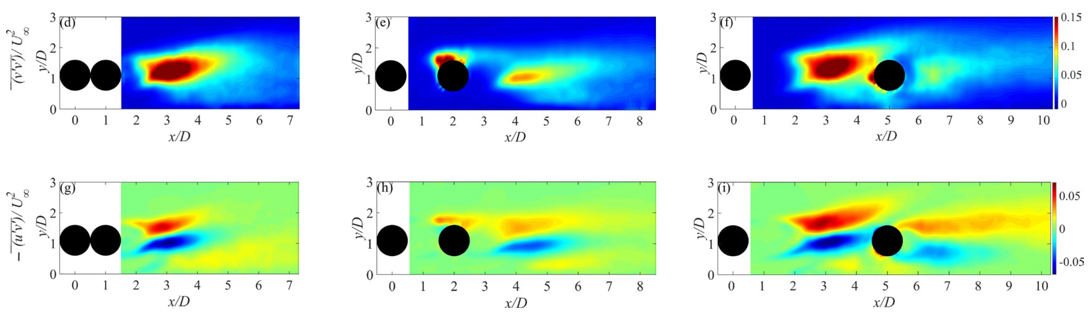
3.3. The Reynolds Stresses and Turbulent Transport

The examination of turbulent properties is essential for understanding the wake dynamics of pipelines in flow fields [49]. We conducted an investigation into the impacts of L / D on the turbulent characteristics at G / D = 0.6 .
The study analyzes the mean Reynolds stresses for three spacing ratios, as shown in Figure 13. It is obvious that the streamwise Reynolds normal stresses u u ¯ / U 2 are concentrated in the shear layers of each cylinder, the cylinders’ wake regions, and the wall at Figure 13a–c. This suggests that the shedding vortices, the reattachment of the shear layer (when L / D = 2 ), and the impinging of the wake vortex from the upstream cylinder on the downstream one (when L / D = 5 ) have produced strong streamwise velocity fluctuations. The evolution of near-wall secondary vortices also contributes to u u ¯ / U 2 . The magnitude of u u ¯ / U 2 behind the downstream cylinder is weaker at L / D = 2 compared to that of L / D = 1 and L / D = 5 . It is evident that the cavity-like squarish structure between the two tandem cylinders and the shear layer reattachment might reduce the magnitude of u u ¯ / U 2 behind the downstream cylinder.
As shown in Figure 13d–f, the vertical Reynolds normal stresses are concentrated in the region of the cylinder wake and the surface of the downstream cylinder due to the wake vortex impingement (when L / D = 5 ) and shear layer reattachment (when L / D = 2 ) from the upstream one. The magnitude of v v ¯ / U 2 decreases significantly with the increase in L / D . In addition, in Figure 13d,f, the distributions of v v ¯ / U 2 of L / D = 5 are presented in the upstream cylinder wake area. From Figure 13g–i, the Reynolds shear stresses are mainly distributed in the wake area, which suggests that there are strong velocity fluctuations.
We analyze the turbulent diffusion T / U 3 / D ) and the production term P / U 3 / D ) in the transport equation of turbulent kinetic energy, which are crucial in reflecting the turbulent transport characteristics.
As shown in Figure 14a–c, the concentrations of turbulent kinetic energies k / U 2 are mainly caused by the wake shedding vortices. At L / D = 1 , the k / U 2 are mainly presented behind the downstream cylinder, which reflect the wake shedding vortices of downstream cylinder. Near the wall, the secondary vortex causes turbulent kinetic energies, which are also shown in He et al. [50]. At L / D = 2 , the shear layers of the upstream cylinder are reattached to the downstream one, and this brings concentrated turbulent kinetic energies above the downstream cylinder. At L / D = 5 , the shedding vortices of the upstream cylinder cause strong turbulent kinetic energies, while the k / U 2 behind the downstream cylinder are weaker and reflect weaker vortex shedding, which agrees with the results shown in Figure 12. A similar investigation is also reported in the study of Li et al. [2]. The k / U 2 behind the downstream cylinder are decreased as L / D increases, which might be attributed to the weaker wake vortices of the downstream cylinder.
In Figure 14d–f, the concentrated production term is mainly presented in the wake area, which resembles the distributions of k / U 2 . For the three spacing ratios, it is observed that the wake vortices and secondary vortex make significant contributions to the production term. At L / D = 1 , the flow resembles that of a single cylinder positioned near the wall, and the shedding vortices of the downstream cylinder bring a concentrated production term. As L / D increases from 2 to 5, the magnitudes of the production term behind the upstream cylinder present an increase, while the magnitudes of the production term behind the downstream cylinder are decreased. At L / D = 5 , the wake vortices of the upstream cylinder interact with the downstream one when the former evolves downstream, and the vorticities of the wake vortices of the downstream cylinder are decreased, which lead to weaker production term. The variations in the magnitude of the production term may indicate the transfer of kinetic energy in the interaction between the fluid and the solid, thus affecting the scouring process around the two tandem cylindrical pipes [51].
The distributions of the turbulent diffusion term are presented in Figure 14g–i. The turbulent diffusion term T / U 3 / D ) reflects the averaged kinetic energies of the irregular fluctuations [37]. The distributions of T / U 3 / D ) are deflected from the wall due to the effects of the wall. In addition, the magnitude of the turbulent diffusion term behind the downstream cylinder is decreased as L / D is increased from 1 to 5, which is similar to the variations in the turbulent kinetic energies and the production term. This finding reflects the reductions in velocity fluctuations behind the downstream cylinder with increasing L / D . This is mainly attributed to the reattachment of the shear layer and the impingement of the wake vortices of the upstream cylinder, which lead to weaker wake vortices of the downstream one, and the velocity fluctuations are decreased.
Finally, the effects of L / D on the flow physics of the near-wall tandem cylinders are discussed. According to the flow characteristics, the spacing ratios are divided into three regions: (I) the “single blunt body” regime at L / D = 1 , the wake of the two tandem cylinders resembles that of the single cylinder; (II) the “shear layer reattachment” regime at L / D = 2 and the shear layers of the upstream cylinder reattached to the downstream one; and (III) the “impinging” regime at L / D = 5 and the wake shedding vortices from the upstream cylinder would impinge on the downstream one. In addition, it is found that G / D and L / D significantly affect S t , and the reasons for the variations in Strouhal number are discussed. At L / D = 1 , the rise in the gap flow below the tandem cylinders is enhanced when G / D is decreased from 1 to 0.3, and the interaction between the gap flow and the cylinders’ shear layers leads to the increase in S t . However, at L / D = 2 and 5 , the S t firstly increases and then decreases as G / D decreases. When G / D decreases from 0.6 to 0.3, the gap flow becomes weaker due to the wake interference from the two cylinders with an intermediate gap, the formation of the wake vortices is slightly suppressed, and the S t is reduced. The wake vortices are mainly shed from the downstream cylinder at L / D = 2 and the shedding of the wake vortices of the two cylinders is investigated at L / D = 5 . For L / D = 5 , at G / D = 0.6 and 1.0 , the S t of the two cylinders are identical, which indicates the “co-shedding” flow regime. At G / D = 0.3 , the S t of the downstream cylinder is smaller than that of the upstream one. Moreover, for the three gap ratios, it is found that the S t gradually decreases as L / D increases. For G / D = 0.3 , there is nearly a 49.98 % decrease from S t = 0.3295 at L / D = 1 to S t = 0.1648 at L / D = 5 , which is larger than the reductions in cases of G / D = 0.6 and G / D = 1 .

4. Conclusions

The experimental research into the flow of two tandem circular cylinders in proximity to a wall is conducted by using PIV techniques. The R e is 2.0 × 10 3 , and three gap ratios ( G / D = 0.3 , 0.6, and 1) and three spacing ratios ( L / D = 1 , 2, and 5) are selected. The flow physics and turbulent characteristics are investigated, and the influences of L / D on the evolution of flow structures are studied. The primary concluding remarks are shown.
The influence of L / D on flow characteristics are presented. At L / D = 1 , the lower shear layer of the downstream cylinder induces deflection of the wall shear layer, and there is a “pairing” process between the former and the latter. In addition, the separation bubble exists behind the downstream cylinder, and the size of the separation bubble is decreased as G / D increases. At L / D = 2 and G / D = 0.3 , there is an interrupted “pairing” process between the lower shear layer of the upstream cylinder and the wall shear layer, and a small separation bubble is formed behind the upstream cylinder. At L / D = 1 , the Strouhal number ( S t ) is increased as G / D decreases. For the three gap ratios, the S t gradually decreases as L / D increases. At G / D = 0.3 , there is nearly a 49.98 % decrease from S t = 0.3295 at L / D = 1 to S t = 0.1648 at L / D = 5 , which is larger than the reductions in cases of G / D = 0.6 and G / D = 1 .
The effects of L / D on the evolution of flow structure at G / D = 0.6 are investigated in detail. At L / D = 1 , the shedding of wake vortices resembles that of a single near-wall cylinder, and the production of a secondary vortex is triggered. As L / D increases to 2 , a cavity-like flow structure with a square shape between the two tandem cylinders becomes apparent. In addition, the upstream cylinder’s lower shear layer induces the production of a small secondary vortex, and the latter is not dissipated and is mainly located at x / D = 1.7 . However, the secondary vortex generated by the downstream cylinder’s lower wake vortex moves downstream along the wall. At L / D = 5 , the upper wake vortices of the upstream cylinder merge with those from the downstream cylinders. Meanwhile, the lower wake vortex of the upstream cylinder directly impinges on the surface of the downstream cylinder.
The turbulent characteristics at G / D = 0.6 are affected by L / D . As L / D increases from 1 to 5 , the magnitudes of Reynolds streamwise normal stresses behind the downstream cylinder are decreased firstly and then increased; however, the magnitudes of the Reynolds vertical stresses behind the downstream cylinder are decreased. The production and diffusion of turbulent kinetic energy behind the downstream cylinder are decreased as L / D increases, and this is mainly due to the weakened incoming flow and reduced velocity fluctuations of the shear layer and the wake vortices of the upstream cylinder.
The investigations into the wake characteristics and flow structures of near-wall tandem cylinders are helpful for enhancing understanding of the flow mechanisms of tandem marine pipelines, and the combination of PIV experiments and CFD simulations will be conducted to provide rich results in further studies.

Supplementary Materials

The following supporting information can be downloaded at: https://0-www-mdpi-com.brum.beds.ac.uk/article/10.3390/jmse12050721/s1.

Author Contributions

Investigation, X.Q., X.J. and Y.T.; methodology, X.Q. and X.J.; experiments, X.Q., X.J., J.Z. and J.L.; writing—review and editing, X.Q., X.J., Y.T., J.Z. and J.L.; writing—original draft, X.Q., X.J. and J.Z.; supervision, Y.L.; conceptualization, Y.L.; funding acquisition, Y.L. All authors have read and agreed to the published version of the manuscript.

Funding

This research was funded by the National Natural Science Foundation of China (Grant No. 12032016 and No. 12372277).

Institutional Review Board Statement

Not applicable.

Informed Consent Statement

Not applicable.

Data Availability Statement

The data used in the article can be provided on request.

Acknowledgments

Thanks for the support of the National Natural Science Foundation of China (Grant No. 12032016 and No. 12372277) and the reviewers’ valuable opinions.

Conflicts of Interest

The authors declare no conflicts of interest.

References

  1. Alam, M.M.; Zhou, Y. Flow around two side-by-side closely spaced circular cylinders. J. Fluids Struct. 2007, 23, 799–805. [Google Scholar] [CrossRef]
  2. Li, Z.; Prsic, M.A.; Ong, M.C.; Khoo, B.C. Large Eddy Simulations of flow around two circular cylinders in tandem in the vicinity of a plane wall at small gap ratios. J. Fluids Struct. 2018, 76, 251–271. [Google Scholar] [CrossRef]
  3. Prsic, M.A.; Ong, M.C.; Pettersen, B.; Myrhaug, D. Large Eddy simulations of flow around tandem circular cylinders in the vicinity of a plane wall. J. Mar. Sci. Tech. 2019, 24, 338–358. [Google Scholar] [CrossRef]
  4. Wu, G.F.; Lin, W.Q.; Du, X.Q.; Shi, C.L.; Zhu, J.Y. On the flip-flopping phenomenon of two side-by-side circular cylinders at a high subcritical Reynolds number of 1.4 × 10⁵. Phys. Fluids 2020, 32, 094112. [Google Scholar] [CrossRef]
  5. Eizadi, H.; An, H.W.; Zhou, T.M.; Zhu, H.J.; Cheng, L. Wake transitions of six tandem circular cylinders at low Reynolds numbers. Phys. Fluids 2022, 34, 023605. [Google Scholar] [CrossRef]
  6. Lin, W.J.; Lin, C.; Hsieh, S.C.; Dey, S. Flow characteristics around a circular cylinder placed horizontally above a plane boundary. J. Eng. Mech. 2009, 135, 697–716. [Google Scholar] [CrossRef]
  7. Kiya, M.; Arie, M.; Tamura, H.; Mori, H. Vortex shedding from two circular cylinders in staggered arrangement. ASME J. Fluids Eng. 1980, 102, 166–173. [Google Scholar] [CrossRef]
  8. Wang, X.K.; Zhang, J.-X.; Hao, Z.; Zhou, B.; Tan, S.K. Influence of wall proximity on flow around two tandem circular cylinders. Ocean Eng. 2015, 94, 36–50. [Google Scholar] [CrossRef]
  9. Hu, D.; Tang, W.; Sun, L.; Li, F.; Ji, X.Y. Numerical simulation of local scour around two pipelines in tandem using CFD-DEM method. Appl. Ocean Res. 2019, 93, 101968. [Google Scholar] [CrossRef]
  10. Liu, Y.L.; Qi, L.M.; Zhou, J.K.; Li, J.H.; Tao, Y.Z.; Qiu, X. Experimental research on wake characteristics and vortex evolution of side-by-side circular cylinders placed near a wall. Ocean Eng. 2023, 285, 115268. [Google Scholar] [CrossRef]
  11. Zdravkovich, M.M. The effects of interference between circular cylinders in cross flow. J. Fluids Struct. 1987, 1, 239–261. [Google Scholar] [CrossRef]
  12. Zhou, Y.; Yiu, M.W. Flow structure, momentum and heat transport in a two-tandem-cylinder wake. J. Fluid Mech. 2006, 548, 17–48. [Google Scholar] [CrossRef]
  13. Xu, G.; Zhou, Y. Strouhal numbers in the wake of two inline cylinders. Exp. Fluids 2004, 37, 248–256. [Google Scholar] [CrossRef]
  14. Zhou, Q.; Alam, M.M.; Cao, S.Y.; Liao, H.L.; Li, M.S. Numerical study of wake and aerodynamic forces on two tandem circular cylinders at Re = 103. Phys. Fluids 2019, 31, 45–62. [Google Scholar] [CrossRef]
  15. Lin, J.-C.; Yang, Y.; Rockwell, D. Flow past two cylinders in tandem: Instantaneous and averaged flow structure. J. Fluids Struct. 2002, 16, 1059–1071. [Google Scholar] [CrossRef]
  16. Igarashi, T. Characteristics of the Flow around Two Circular Cylinders Arranged in Tandem: 1st Report. Bull. JSME 1981, 24, 323–331. [Google Scholar] [CrossRef]
  17. Ljungkrona, L.; Norberg, C.; Sundén, B. Free-stream turbulence and tube spacing effects on surface pressure fluctuations for two tubes in an in-line arrangement. J. Fluids Struct. 1991, 5, 701–727. [Google Scholar] [CrossRef]
  18. Ljungkrona, L.; Sundén, B. Flow visualization and surface pressure measurement on two tubes in an inline arrangement. Exp. Therm Fluid Sci. 1993, 6, 15–27. [Google Scholar] [CrossRef]
  19. Wu, J.; Welch, L.W.; Welsh, M.C.; Sheridan, J.; Walker, G.J. Spanwise wake structures of a circular cylinder and two circular cylinders in tandem. Exp. Therm. Fluid Sci. 1994, 9, 299–308. [Google Scholar] [CrossRef]
  20. Sumner, D. Two circular cylinders in cross-flow: A review. J. Fluids Struct. 2010, 26, 849–899. [Google Scholar] [CrossRef]
  21. Alam, M.M. The aerodynamics of a cylinder submerged in the wake of another. J. Fluids Struct. 2014, 51, 393–400. [Google Scholar] [CrossRef]
  22. Harichandan, A.B.; Roy, A. Numerical investigation of flow past single and tandem cylindrical bodies in the vicinity of a plane wall. J. Fluids Struct. 2012, 33, 19–43. [Google Scholar] [CrossRef]
  23. Rao, A.; Thompson, M.C.; Leweke, T.; Hourigan, K. Dynamics and stability of the wake behind tandem cylinders sliding along a wall. J. Fluid Mech. 2013, 722, 291–316. [Google Scholar] [CrossRef]
  24. D’Souza, J.E.; Jaiman, R.K.; Mak, C.K. Dynamics of tandem cylinders in the vicinity of a plane moving wall. Comput. Fluids 2016, 124, 117–135. [Google Scholar] [CrossRef]
  25. Tang, G.Q.; Chen, C.Q.; Zhao, M.; Lu, L. Numerical simulation of flow past twin near-wall circular cylinders in tandem arrangement at low Reynolds number. Water Sci. Eng. 2015, 8, 1–11. [Google Scholar] [CrossRef]
  26. Sciacchitano, A.; Wieneke, B. PIV uncertainty propagation. Meas. Sci. Technol. 2016, 27, 084006. [Google Scholar] [CrossRef]
  27. Qu, Y.; Wang, J.J.; Feng, L.H.; He, X. Effect of excitation frequency on flow characteristics around a square cylinder with a synthetic jet positioned at front surface. J. Fluid Mech. 2019, 880, 764–798. [Google Scholar] [CrossRef]
  28. Feng, L.H.; Wang, J.J.; Pan, C. Proper orthogonal decomposition analysis of vortex dynamics of a circular cylinder under synthetic jet control. Phys. Fluids 2011, 23, 014106. [Google Scholar] [CrossRef]
  29. Berkooz, G.; Holmes, P.; Lumley, J.L. The proper orthogonal decomposition in the analysis of turbulent flows. Annu. Rev. Fluid Mech. 1993, 25, 539–575. [Google Scholar] [CrossRef]
  30. Van Oudheusden, B.W.; Scarano, F.; Van Hinsberg, N.P.; Watt, D.W. Phase-resolved characterization of vortex shedding in the near wake of a square-section cylinder at incidence. Exp. Fluids 2005, 39, 86–98. [Google Scholar] [CrossRef]
  31. Qu, Y.; Wang, J.J.; Sun, M.; Feng, L.H.; Pan, C. Wake vortex evolution of square cylinder with a slot synthetic jet positioned at the rear surface. J. Fluid Mech. 2017, 812, 940–996. [Google Scholar] [CrossRef]
  32. Zhou, J.; Adrian, R.J.; Balachandar, S.; Kendall, T.M. Mechanisms for generating coherent packets of hairpin vortices in channel flow. J. Fluid Mech. 1999, 387, 353–396. [Google Scholar] [CrossRef]
  33. Jeong, J.; Hussain, F. On the identification of a vortex. J. Fluid Mech. 1995, 185, 69–94. [Google Scholar] [CrossRef]
  34. Hauser, H.; Hagen, H.; Theisel, H. Topology-Based Methods in Visualization; Springer: Berlin/Heidelberg, Germany, 2007. [Google Scholar]
  35. Karches, T. Towards a Dynamic Compartmental Model of a Lamellar Settler. Symmetry 2023, 15, 864. [Google Scholar] [CrossRef]
  36. He, G.S.; Wang, J.J. Flat plate boundary layer transition induced by a controlled near-wall circular cylinder wake. Phys. Fluids 2015, 27, 024106. [Google Scholar] [CrossRef]
  37. Tang, Z.Q.; Wu, Y.H.; Jia, Y.X.; Jiang, N. PIV measurements of a turbulent boundary layer perturbed by a wall-mounted transverse circular cylinder element. Flow Turbul. Combust. 2018, 100, 365–389. [Google Scholar] [CrossRef]
  38. Mohebi, M.; Wood, D.H.; Martinuzzi, R.J. The turbulence structure of the wake of a thin flat plate at post-stall angles of attack. Exp. Fluids 2017, 58, 67. [Google Scholar] [CrossRef]
  39. Abdelhady, M.; Wood, D.H. An investigation of the wakes of stranded cables using particle image velocimetry. Phys. Fluids 2021, 33, 035132. [Google Scholar] [CrossRef]
  40. He, G.S.; Wang, J.J.; Pan, C.; Feng, L.H.; Gao, Q. Vortex dynamics for flow over a circular cylinder in proximity to a wall. J. Fluid Mech. 2017, 812, 698–720. [Google Scholar] [CrossRef]
  41. Zhou, J.K.; Qiu, X.; Li, J.H.; Liu, Y.L. Vortex evolution of flow past the near-wall circular cylinder immersed in a flat-plate turbulent boundary layer. Ocean Eng. 2022, 260, 112011. [Google Scholar] [CrossRef]
  42. Price, S.J.; Sumner, D.; Smith, J.G.; Leong, K.; Paidoussis, M.P. Flow visualization around a circular cylinder near to a plane wall. J. Fluids Struct. 2002, 16, 175–191. [Google Scholar] [CrossRef]
  43. Zhou, J.K.; Qiu, X.; Li, J.H.; Liu, Y.L. The gap ratio effects on vortex evolution behind a circular cylinder placed near a wall. Phys. Fluids 2021, 33, 037112. [Google Scholar] [CrossRef]
  44. Lengani, D.; Simoni, D.; Ubaldi, M.; Pietro, Z. POD analysis of the unsteady behavior of a laminar separation bubble. Exp. Ther. Fluid Sci. 2014, 58, 70–79. [Google Scholar] [CrossRef]
  45. Dipankar, A.; Sengupta, T.K. Flow past a circular cylinder in the vicinity of a plane wall. J. Fluids Struct. 2005, 20, 403–423. [Google Scholar] [CrossRef]
  46. Chen, L.F.; Wang, Y.T.; Sun, S.; Wang, S.Q. The effect of boundary shear flow on hydrodynamic forces of a pipeline over a fully scoured seabed. Ocean Eng. 2020, 206, 107326. [Google Scholar] [CrossRef]
  47. Chen, W.L.; Ji, C.N.; Xu, D.; Zhang, Z.M. Vortex-induced vibrations of two inline circular cylinders in proximity to a stationary wall. J. Fluids Struct. 2020, 94, 102958. [Google Scholar] [CrossRef]
  48. Liu, J.; Gao, F.P. Triggering mechanics for transverse vibrations of a circular cylinder in a shear flow: Wall-proximity effects. J. Fluids Struct. 2022, 108, 103423. [Google Scholar] [CrossRef]
  49. Ikhennicheu, M.; Druault, P.; Gaurier, B.; Germain, G. Turbulent kinetic energy budget in a wall-mounted cylinder wake using PIV measurements. Ocean Eng. 2020, 210, 107582. [Google Scholar] [CrossRef]
  50. He, G.S.; Pan, C.; Feng, L.H.; Gao, Q.; Wang, J.J. Evolution of Lagrangian coherent structures in a cylinder-wake disturbed flat plate boundary layer. J. Fluid Mech. 2016, 792, 274–306. [Google Scholar] [CrossRef]
  51. Hu, X.F.; Zhang, X.S.; You, Y.X. On the flow around two circular cylinders in tandem arrangement at high Reynolds numbers. Ocean Eng. 2019, 189, 106301. [Google Scholar] [CrossRef]
Figure 1. (a) The schematic representation of experimental model, and (b) the side view.
Jmse 12 00721 g001
Figure 2. The normalized velocity ( U / U ) against normalized distance η = y U / ν X from plane boundary.
Jmse 12 00721 g002
Figure 3. Power spectral densities of vertical fluctuating velocities ( v ) and S t of downstream cylinder at L / D = 3 .
Jmse 12 00721 g003
Figure 4. The distributions of mean streamwise velocity U / U   as well as the distributions of streamlines. (a) L/D = 1, G/D = 0.3; (b) L/D = 1, G/D = 0.6; (c) L/D = 1, G/D = 1.0; (d) L/D = 2, G/D = 0.3; (e) L/D = 2, G/D = 0.6; (f) L/D = 2, G/D = 1.0; (g) L/D = 5, G/D = 0.3; (h) L/D = 5, G/D = 0.6; (i) L/D = 5, G/D = 1.0.
Jmse 12 00721 g004
Figure 5. The distributions of mean spanwise vorticity ω z . (a) L/D = 1, G/D = 0.3; (b) L/D = 1, G/D = 0.6; (c) L/D = 1, G/D = 1.0; (d) L/D = 2, G/D = 0.3; (e) L/D = 2, G/D = 0.6; (f) L/D = 2, G/D = 1.0; (g) L/D = 5, G/D = 0.3; (h) L/D = 5, G/D = 0.6; (i) L/D = 5, G/D = 1.0.
Jmse 12 00721 g005
Figure 6. Power spectral densities of vertical fluctuating velocity ( ν ) in the wake region of the downstream cylinder. (a) L/D = 1, G/D = 0.3; (b) L/D = 1, G/D = 0.6; (c) L/D = 1, G/D = 1.0; (d) L/D = 2, G/D = 0.3; (e) L/D = 2, G/D = 0.6; (f) L/D = 2, G/D = 1.0; (g) L/D = 5, G/D = 0.3; (h) L/D = 5, G/D = 0.6; (i) L/D = 5, G/D = 1.0.
Jmse 12 00721 g006
Figure 7. The power spectral density of the vertical fluctuating velocity ( ν ) in the wake region of the upstream cylinder for L / D = 5 . (a) L/D = 5, G/D = 0.3; (b) L/D = 5, G/D = 0.6; (c) L/D = 5, G/D = 1.0.
Jmse 12 00721 g007
Figure 8. The variation in S t versus the L / D of the downstream cylinder for the present study and the previous results of Wang et al. [8] and Tang et al. [35].
Jmse 12 00721 g008
Figure 9. Percentages of total energy for the energy of the first 50 modes at nine cases.
Jmse 12 00721 g009
Figure 10. The evolutions of flow structures based on Λ c i fields for L / D = 1 and G / D = 0.6 , superimposed on the streamlines. (a) t , (b) t + t , (c) t + 2 t , and (d) t + 3 t .
Jmse 12 00721 g010aJmse 12 00721 g010b
Figure 11. The evolution of flow structures based on Λ c i fields for L / D = 2 and G / D = 0.6 , superimposed on the streamlines. (a) t , (b) t + t , (c) t + 2 t , and (d) t + 3 t .
Jmse 12 00721 g011
Figure 12. The evolution of flow structures based on Λ c i fields for L / D = 5 and G / D = 0.6 , superimposed on the streamlines. (a) t , (b) t + t , (c) t + 2 t , and (d) t + 3 t .
Jmse 12 00721 g012
Figure 13. (ac) The streamwise Reynolds normal stresses u u ¯ / U 2 , (df) the Reynolds normal stresses v v ¯ / U 2 , and (gi) the Reynolds shear stresses u v ¯ / U 2 at G / D = 0.6 .
Jmse 12 00721 g013aJmse 12 00721 g013b
Figure 14. (ac) The turbulent kinetic energy k / U 2 , (df) the production term P / U 3 / D ) , and (gi) the turbulent diffusion term T / U 3 / D ) at the G / D = 0.6 .
Jmse 12 00721 g014aJmse 12 00721 g014b
Table 1. Selected previous studies on two tandem cylinders positioned near a wall.
AuthorMethod R e L / D G / D Research Object
Rao et al. [23]Numerical simulation 20 2 × 10 2 0.1 10 0 Wake characteristics
Tang et al. [25]Numerical simulation 2 × 10 2 1.0 4.0 0.25 2.0 C D , C L , S t
Wang et al. [8]PIV 6.3 × 10 3 1.5 6.0 0.15 2.0 C D , C L , S t and flow regimes
D’Souza et al. [24]Numerical simulation 2 × 10 2 1.5 8.0 0.2 5.0 force and wake dynamics
Li et al. [2]Large eddy simulations 1.31 × 10 4 2 and 5 0.1 ,   0.3 and 0.5 C D , C L and flow characteristics
Prsic et al. [3]Large eddy simulations 1.31 × 10 4 2 and 5 0.6 and 1 C D , C L and flow regimes
Present studyPIV 2 × 10 3 1 ,   2 and 5 0.3 ,   0.6 ,   1.0 S t , vortex evolution, vortex interaction
Disclaimer/Publisher’s Note: The statements, opinions and data contained in all publications are solely those of the individual author(s) and contributor(s) and not of MDPI and/or the editor(s). MDPI and/or the editor(s) disclaim responsibility for any injury to people or property resulting from any ideas, methods, instructions or products referred to in the content.

