
Study on Ring Deformation and Contact Characteristics of Thin-Walled Bearing for RV Reducer
School of Mechanical Engineering, Qilu University of Technology (Shandong Academy of Sciences), Jinan 250353, China
*
Author to whom correspondence should be addressed.
Appl. Sci. 2024, 14(9), 3741; https://0-doi-org.brum.beds.ac.uk/10.3390/app14093741
Submission received: 18 March 2024
/
Revised: 23 April 2024
/
Accepted: 25 April 2024
/
Published: 27 April 2024
(This article belongs to the Special Issue Advances and Challenges in Reliability and Maintenance Engineering)
Abstract
:The thin-walled rings of the RV reducer main bearings are prone to structural elastic deformation, which can significantly change the bearing mechanical characteristics. According to the actual assembly state of the RV reducer, the simulation model of the planetary frame–main bearings–pin gear housing is established considering the ring deformation. The model was used to calculate and comparatively analyze the ring deformation and contact characteristics of thin-walled bearings under rigid and flexible conditions, on the basis of which the mechanism of ring deformation was described, and the effects of load conditions, ring thickness and radial clearance on ring deformation, flexible contact characteristics, and ultimate carrying capacity were analyzed. The results show that the distribution of contact loads is the main factor affecting the ring deformation. The ring deformation can optimize the bearing contact characteristics, and the greater the deformation, the more pronounced the optimization effect. However, excessive ring deformation makes the contact ellipse more susceptible to truncation, which, in turn, reduces the ultimate carrying capacity. This study indicates a 38.2% decrease in the carrying capacity of the flexible ring model compared to that of the rigid ring model. In this paper, the effect of ring deformation on bearing mechanical characteristics is deeply discussed. The research results have important guiding significance for the structural optimization design of thin-walled bearings.
1. Introduction
The RV reducer finds extensive applications within industrial robotics [1]. A pair of thin-walled angular contact ball bearings are installed on the pin gear housing and planetary frame to bear the full external load of the reducer. The main bearing and pin gear housing are usually thin-walled structures, which are prone to elastic deformation, resulting in changes in bearing contact characteristics. Consequently, it is critical to develop a bearing model incorporating structural elastic deformation considerations and analyze the effect of various factors on the ring deformation and flexible contact characteristics.
The traditional bearing analysis theory is based on the rigid ring hypothesis, which holds that elastic deformation primarily takes place within the ball–raceway contact area, while the overall shape of the ring does not change [2]. This hypothesis provides an excellent approximate method for bearing analysis with large ring thicknesses. For instance, Zhang et al. [3] proposed a critical criterion for the ball–raceway separation. They indicated that the ball separates from the inner raceway and only contacts the outer raceway due to the inertial effect, which causes the difference in the contact state between the ball and the inner raceway in the static and quasi-static models under the same load condition. Xie et al. [4] studied the influences of load conditions and structural parameters on the moment rigidity and rotation accuracy of the main bearings for the RV reducer. Deng et al. [5] analyzed the force state of the main bearings for the RV reducer under extreme load conditions. Regarding carrying capacity, allowable contact stress [6], fatigue life [7,8], deflection, and elliptical truncation [9] are usually used to characterize the carrying capacity. Harris et al. [10] propose a method for computing the axial carrying capacity in cases where the contact ellipse fails to surpass the raceway rib, but their method only applies to purely axial force conditions. Xu et al. [11] improved this method and applied it to arbitrary working conditions, then studied the influences of geometric parameters and radial force on the carrying performance of the bearing. Wang et al. [12] explored the influence of the elliptical truncation rate on the bearing contact characteristics. The findings indicate that elliptical truncation leads to a relocation of the ball–raceway maximum contact stress position from the contact center to the raceway edge, and a 10% elliptical truncation would lead to a 50% reduction in fatigue life. Gao et al. [13] used the maximum contact stress to characterize the carrying capacity. They compared the sensitivity of different structural parameters influencing the carrying capacity. He et al. [14] investigated how the mesh size of the finite element model impacted the carrying capacity. Their findings indicate that for simulation results closest to theoretical predictions, the mesh size should not exceed half of the short semi-axis length of the Hertzian contact ellipse. However, previous researchers only studied the carrying capacity of bearings under rigid conditions, with little attention paid to the effect of ring deformation on carrying capacity.
Contemporary advanced bearing technology toward the direction of thin walls and component integration, and some studies indicate that ring deformation can change the bearing contact characteristics [15,16]. Harris et al. [17] were the first to consider the influence of ring deformation. They used the outer ring two-point support condition to study planetary gear bearings. They found that the ring deformation worsens the ball–raceway contact state, significantly reducing bearing fatigue life. Cavallaro et al. [18] described the ring deformation based on the Roark formula and introduced it into the bearing balance equation. They found that structural deformation causes the expansion of the loaded zone and a decrease in maximum contact stress. Wagner et al. [19] found that compared to the rigid outer ring, the elastic deformation of the ring amplifies the absolute radial displacement of the inner ring while diminishing its radial stiffness. Liu et al. [20] demonstrated that structural elastic deformation significantly affects bearing vibration. Hao et al. [21] created a simulation model for the bearing system to investigate how temperature influenced ring displacement. Their findings indicate that the outer ring displacement is influenced by the structure of the bearing housing, and the ring displacement exhibits a wavy pattern due to ring deformation. Mao et al. [22] analyzed the impact of the clearance fit on the outer ring deformation. The results indicate that an appropriate clearance fit can improve the bearing contact characteristics and lubrication state and extend the fatigue life. Unfortunately, this study ignored the structural elasticity of the bearing housing. Wang et al. [23] applied the deformation coordination theory to derive the deformation rules of the ring under different assembly states of the shaft and ring. Furthermore, they concluded that cage flexibility could alleviate the skid phenomenon [24]. However, the above studies are focused on radial bearings, with few investigations on angular contact ball bearings, which are primarily subjected to axial loads. Moreover, the mechanism of ring deformation and the influence of ring deformation on flexible contact characteristics have not been fully investigated.
In this paper, according to the actual assembly state and restraint conditions of the RV reducer, a simulation model of the planetary frame–main bearings–pin gear housing, which can fully consider structural elastic deformation, is established. Firstly, the ring deformation and contact characteristics of the two main bearings were comparatively analyzed under normal operating conditions of the RV reducer. Then, the effect of load conditions and bearing geometric parameters on ring deformation, ball–raceway contact state, the relative ratio of the maximum load, and ultimate carrying capacity under rigid ring and flexible ring models are given.
2. Theoretical Analysis
2.1. Mathematical Model
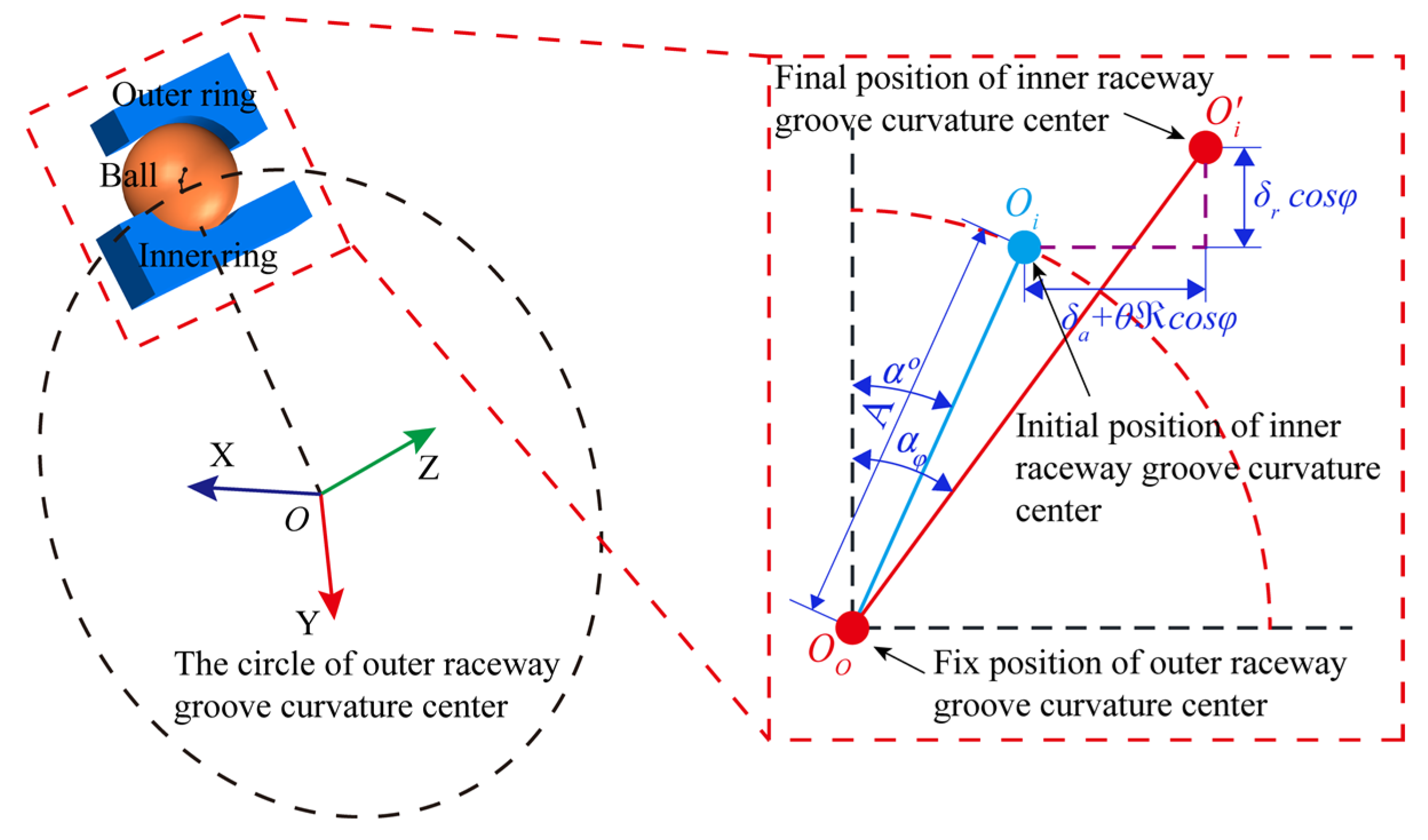
In this study, the bearing outer ring is in a fixed state, while the inner ring is rotating. Figure 1 illustrates the relative displacement relationship of the curvature centers of the inner and outer raceways before and after the bearing is loaded. Before the bearing is loaded, there is no contact deformation between the ball and the raceway, and the distance A between the curvature centers of the inner and outer raceways can be expressed as
where fi and fo are the curvature coefficients of the inner and outer raceways, respectively, and Dw is the diameter of the ball.
After the bearing is loaded, the curvature center of the inner raceway changes relative to the curvature center of the outer raceway, and the curvature center of the inner raceway moves from Oi to . According to the geometric relationship in Figure 1, the distance S between the curvature centers of the inner and outer raceways at any ball position φ can be expressed as
where αo is the initial contact angle; δa, δr, θ are the axial, radial, and angular relative displacements of the inner and outer ring; ℜ = dm/2 + (fi − 0.5)Dwcosαo; dm is the pitch diameter of the bearing.
According to Equations (1) and (2), the ball–raceway total contact deformation δn can be expressed as
where δi, δo are the contact deformations of the ball–inner raceway and the ball–outer raceway.
According to the load-displacement relationship of the ball–raceway contact, the expression of the ball–raceway contact load Q is as follows:
where Kn is the load-displacement coefficient, and n = 3/2 for ball bearings. When δn ≤ 0, the ball separates from the raceway, while when δn > 0, the ball makes contact with the raceway. The specific expression for the ball–raceway contact load at any azimuth angle φ can be obtained by substituting Equation (3) into Equation (4):
According to the geometric relationship in Figure 1, the expression of the ball–raceway contact angle at any azimuth angle φ is as follows:
Assuming that the axial force, radial force, and moment applied to the bearing are Fa, Fr, and M, respectively, and that the external load applied to the inner ring should be balanced with the load applied to the inner ring by the balls, then, the balance equation of the inner ring can be written as
where Qk and αk represent the ball–raceway contact load and contact angle at the angular position φk, respectively, and subscript k represents the kth ball.
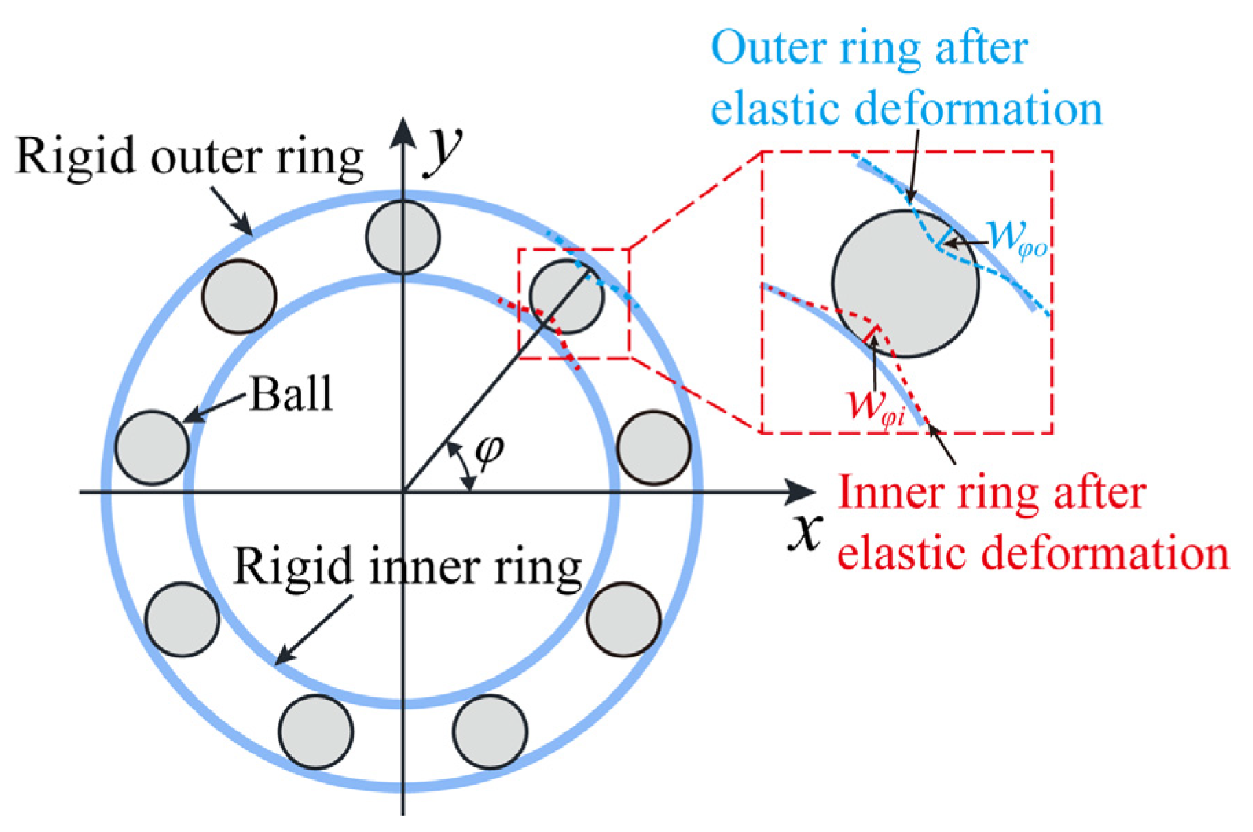
However, due to the influence of substantial external forces, the bending deformation of thin-walled bearing rings is particularly significant, approaching or even exceeding the Hertzian contact deformation. In this case, the influence of radial deflection at arbitrary ring positions on the contact deformation must be considered. Figure 2 shows the radial deflections wφo and wφi caused by the ring deformation at the arbitrary azimuth φ. Then, the ball–raceway radial deflection is
According to Equations (2) and (8), the ball–raceway total radial deformation δφr at any position φ of the ring under the flexible ring model is
where is the radial displacement of the curvature center of the inner ring relative to the curvature center of the outer ring after the bearing is loaded under the rigid ring condition. According to Equation (9), the key to obtaining the bearing contact characteristics under the flexible ring condition is to solve the ball–raceway radial deflection wφ at any position.
Bearing ring bending deformation can be considered a planar problem. According to the thin-walled ring plane bending theory [25], the differential equation for the radial deflection deformation of the ring at the arbitrary azimuth φ is given by
where w is the bending radial displacement of the thin-walled ring relative to the center of the circle; M is the bending moment that causes the curvature of the circle to change (; Q is the ball–raceway contact load; is the ball equidistant angle; E is the elastic modulus of the material; I is the section moment of inertia in bending (; D is the outer diameter of the outer ring; is the inner diameter of the outer ring), and R is the pitch radius of the ring.
The thin-walled ring produces small deflection deformation under external force, and the displacement at any point on the center line of the ring can be decomposed into a radial displacement w and a tangential displacement v, as illustrated in Figure 3. Pr is the radial force; Pt is the tangential force; is the azimuthal angle of the load, and the subscript k represents different load positions in Figure 3. The expression for the trigonometric series of radial displacement and tangential displacement is given by
where a and b are the major and minor axes of contact deformation caused by deflection deformation, respectively, and n is a constant.
The ring is initially in equilibrium, and with the effect of the radial force Pr and the tangential force Pt, the ring deviates from the equilibrium position and produces an imaginary displacement. Thus, the imaginary displacement along the radial direction at the point of force action can be described as
Suppose the ring receives l radial force and j tangential force; then the work executed by all external forces is as follows:
The strain energy of the ring due to deflecting deformation can be written as
By substituting Equations (10) and (12) into Equation (15), the strain energy can be represented by the following equation:
According to the principle of imaginary displacement, the change in strain energy of the ring is equal to the work carried out by the external force; then,
By incorporating Equations (14) and (16) into the equation provided above, the expression of an and bn can be derived as follows:
The radial displacement wp caused by the radial force and the radial displacement wt caused by the tangential force are, respectively,
From the above analysis, the radial deformation wpo and wto of the ball–outer ring and the radial deformation wpi and wti of the ball–inner ring, which are caused by the ring deformation, can be obtained. Therefore, the total contact deformation from the ring deformation at arbitrary azimuth angle φ is
where Io and Ii are the bending moments of inertia of the outer and inner rings, respectively; , , , and represent the radial and tangential forces on the outer and inner rings.
To sum up, considering the ring deformation, the ball–raceway total radial contact deformation is
The ring deformation leads to a change in the ball–raceway total contact deformation. Based on Equations (21) and (22), the geometric equation in the bearing rigid ring model is updated, where the expression of the distance between the curvature centers of the inner and outer raceway can be updated as follows:
The expression of the ball–raceway total contact deformation can be updated as follows:
The expression of the ball–raceway contact angle can be updated as follows:
It is worth noting that after considering the ring deformation, the inner ring equilibrium equations should also include the ring deformation at each ball position φk, and thus, Equation (7) is updated to
Model Solution
The rigid ring model is composed of geometric Equations (1)–(3), Hertz contact Equation (5), and inner ring equilibrium Equation (7). This model is a set of simultaneous nonlinear equations with unknown variables (axial displacement δa, radial displacement δr, and angular displacement θ). The flexible ring model should also consider the ring bending deformation wφ of the ring at each rolling element position and its influence on the bearing contact characteristics. This model is solved by the Newton–Raphson iterative algorithm, and the detailed iterative process is shown in Figure 4. Firstly, the geometric parameters, material parameters, and working condition parameters of the bearing are input, and then the global displacement iteration variables are initialized. The ball–raceway contact deformation is calculated according to the geometric relationship, and the ball–raceway contact state is judged. Then, the ball–raceway contact load is calculated according to the Hertz contact theory. The above results are substituted into the inner ring equilibrium equations, and the Newton–Raphson iterative algorithm is used to solve the inner ring equilibrium equations. Finally, the bearing contact characteristics under the rigid ring conditions are obtained. Based on the rigidity results, the ring bending deformation is analyzed. Then, the contact deformation, contact load, contact angle, and inner ring equilibrium equations are updated. Finally, the above iterative steps are repeated to obtain the ring deformation and bearing contact characteristics under the flexible ring condition.
2.2. Analysis of the Carrying Capacity
Elliptical truncation is not negligible in bearing performance analysis, and there are few studies on the effect of ring deformation on elliptical truncation [26]. The elliptical truncation is used as the judging condition of the carrying capacity of bearings in this paper, and the influences of radial force and geometric parameters on the axial carrying capacity of bearings are analyzed under rigid ring and flexible ring models.
Figure 5 illustrates the geometric relationship between the ball–raceway contact ellipse and the raceway rib. Under the action of axial force, the contact ellipse moves toward the raceway rib until elliptical truncation occurs. The expression for the angle ϕi/o associated with the larger rib of the raceway is
where hi/o represents the large rib height of the inner or outer raceway; ri/o represents the inner or outer raceway groove curvature radius. The expression for the angle φaij/oj associated with the semimajor axis of the contact ellipse is
where a is the semimajor axis of the contact ellipse; the calculation method can be referred to the reference [10].
The ellipse truncation rate is usually used to characterize the degree of the ellipse truncation. The expression of the ellipse truncation rate is as follows:
where αi/o is the ball–raceway contact angle; the contact ellipse is truncated when > 0. However, the contact ellipse is not truncated when < 0. In addition, when = 0, the contact ellipse is not truncated, and the axial force at this time is the axial carrying capacity of the bearing. It is worth noting that the ring deformation can cause a change in αij/oj, which affects the carrying capacity.
2.3. Simulation Model of the RV Reducer Main Bearings
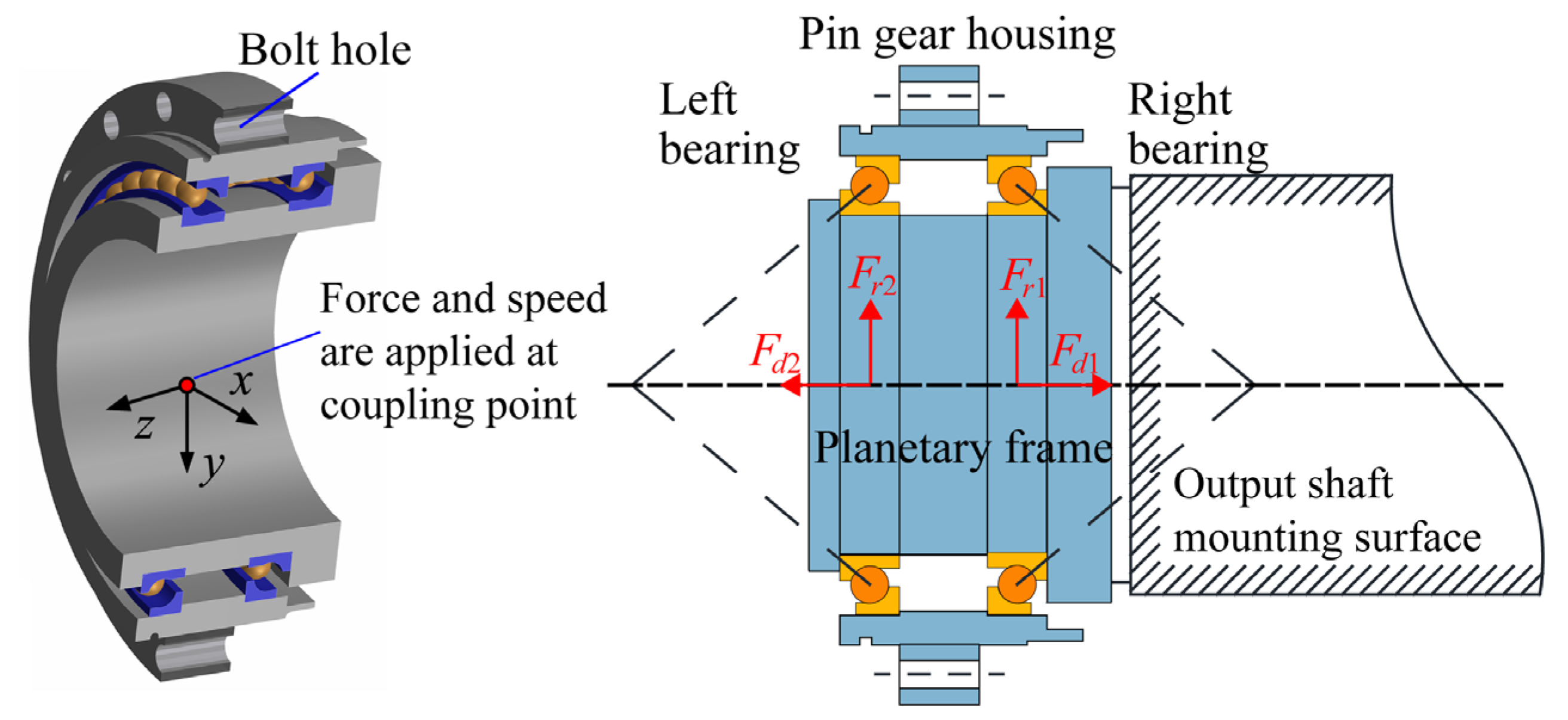
Figure 6 illustrates the assembly diagram of the main bearing for the RV reducer. The bearing outer ring is fixed to the pin gear housing, and the inner ring interferes with the planetary frame. The bolt holes are evenly distributed on the pin gear housing to fix the reducer. Figure 7 shows that the flexible ring model is established based on Romax software(2022) according to the actual structure of the RV reducer. The outer rings are connected with the pin gear housing by RBE3. Fixed constraints are added to all bolt holes on the pin gear housing. The force and speed are applied at the coupling point, which is located at the midpoint of the line connecting the centers of the two main bearings. The main parameters of the thin-walled angular contact ball bearing used in this study are given in Table 1 and Table 2. The data in Table 1 and Table 2 are provided by the BH Technology Group Co., Ltd. (Taizhou, China)
3. Results and Discussion
3.1. Model Validation
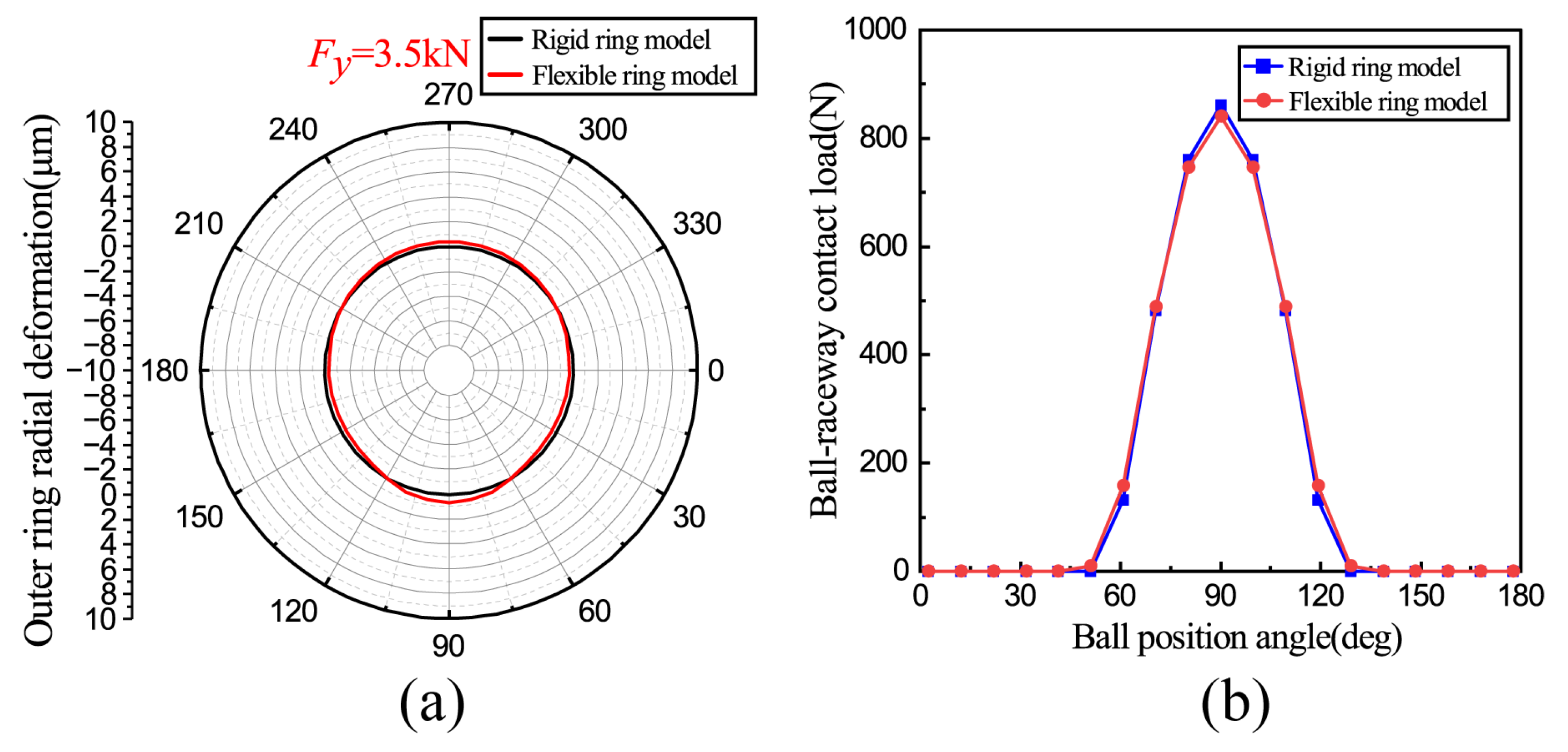
The results of the flexible ring model are contrasted with those obtained from the Harris rigid hypothesis model to confirm the validity of the proposed model [10]. The bearing geometric parameters remain unchanged, and the model approaches the conditions of rigid constraints by increasing the wall thickness and applying the fixed constraints on all the outer surfaces of the pin gear housing. The comparison results show that the ring shape calculated by the flexible ring model is close to the standard circle, and the load distribution curve exhibits an excellent agreement with that of the Harris model, as shown in Figure 8.
3.2. Comparison of Rigid and Flexible Ring Model Results
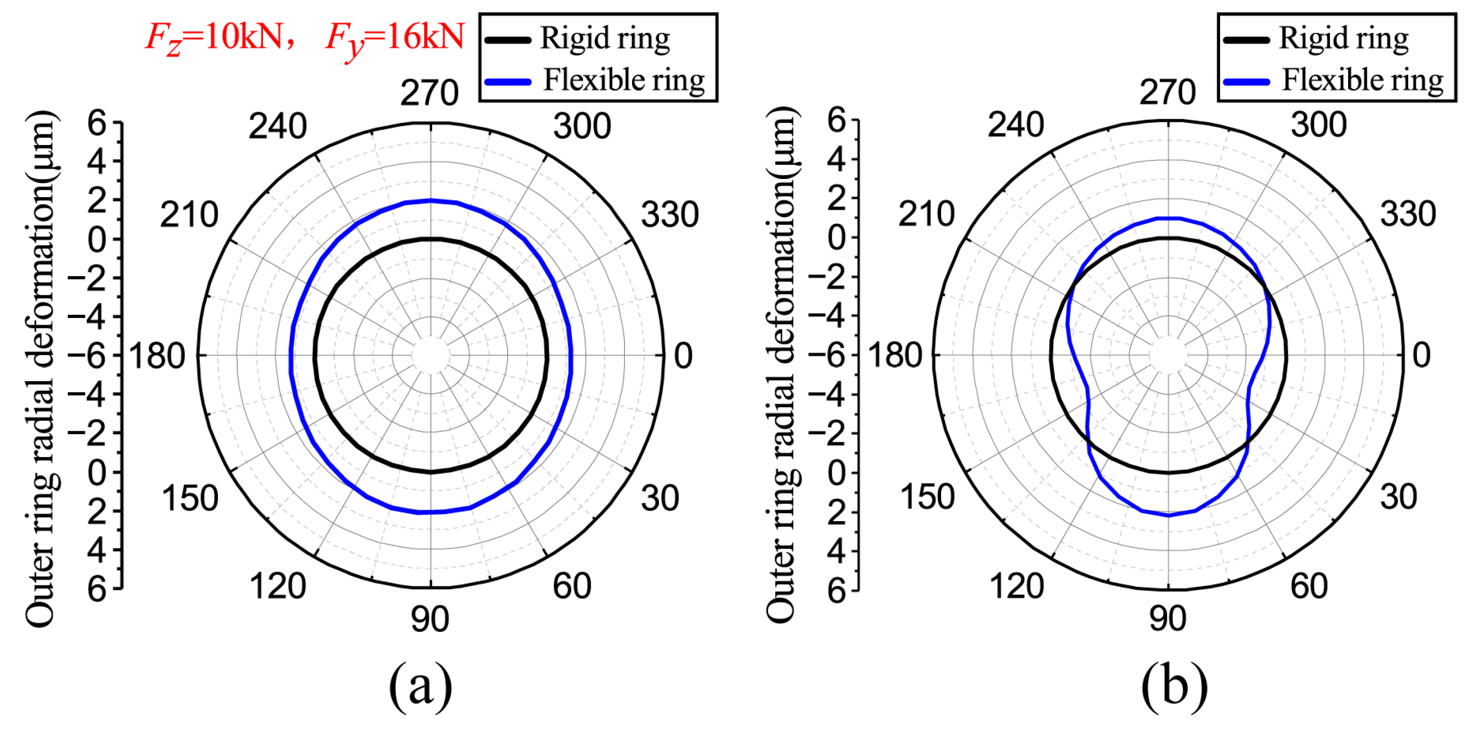
The ring deformation and contact characteristics of the two main bearings are comparative analyses under the normal operating conditions of the RV reducer. As seen in Figure 9, to facilitate the characterization of the ring deformation, the Y-axis denotes the vertical direction, while the X-axis represents the horizontal direction. The ring is deformed irregularly under the action of the ball–raceway contact loads, and the deformation level is in the same micrometer scale as the ball–raceway contact deformation, which further proves the necessity and correctness of the flexible ring model, as shown in Figure 10.
The forces in the y and z directions in Figure 10 are external load conditions for these specific results. Compared with the standard circle of the rigid ring model, the outer ring deformation of the left bearing tends to be an elliptical shape, and the horizontal and vertical diameters become larger, with the maximum increment of the horizontal diameter being 2.4 µm and the maximum increment of the vertical diameter being 4.08 µm. The outer ring deformation of the right bearing appears to be a cam shape, with a decrease in the horizontal diameter and an increase in the vertical diameter. The maximum reduction in the horizontal diameter measures 2.46 µm, while the maximum increase in the vertical diameter is 3.14 µm. The two trends are closely linked to the distribution of the ball–raceway contact load. All balls of the left bearing are loaded, causing the ring diameter to increase, while the contact loads of the right bearing are concentrated in the 90° azimuth area, causing the ring diameter to increase in that direction and decrease in the horizontal direction.
The ring deformation inevitably induces alterations in the bearing contact characteristics. In Figure 11a,b, compared with the rigid ring hypothesis, the ring deformation reduces the maximum contact load of the left bearing from 1294.7 N to 1250 N, representing a decrease of 3.4%, and the maximum contact load of the right bearing from 1382 N to 1296 N, representing a decrease of 6.2%. In Figure 11c,d, the ring deformation leads to a decrease in the contact angles near the 90° azimuth of the left bearing and an increase in the contact angles near the 270° azimuth, resulting in a decreased contact angles within the loaded zone of the right bearing. According to the above content and the analysis of reference [5], compared with the left bearing, the right bearing has more complex ring deformation and worse load distribution due to the different constraint positions and load conditions of the two bearings. Therefore, the subsequent analysis mainly focuses on the right bearing.
3.3. The Effect of Axial Force
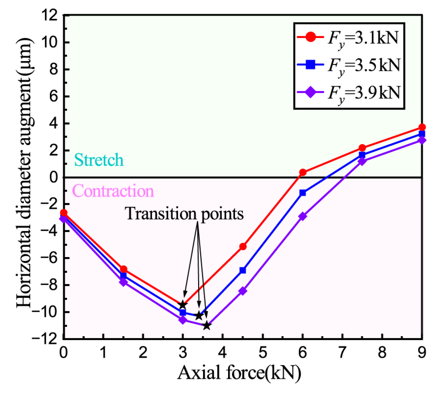
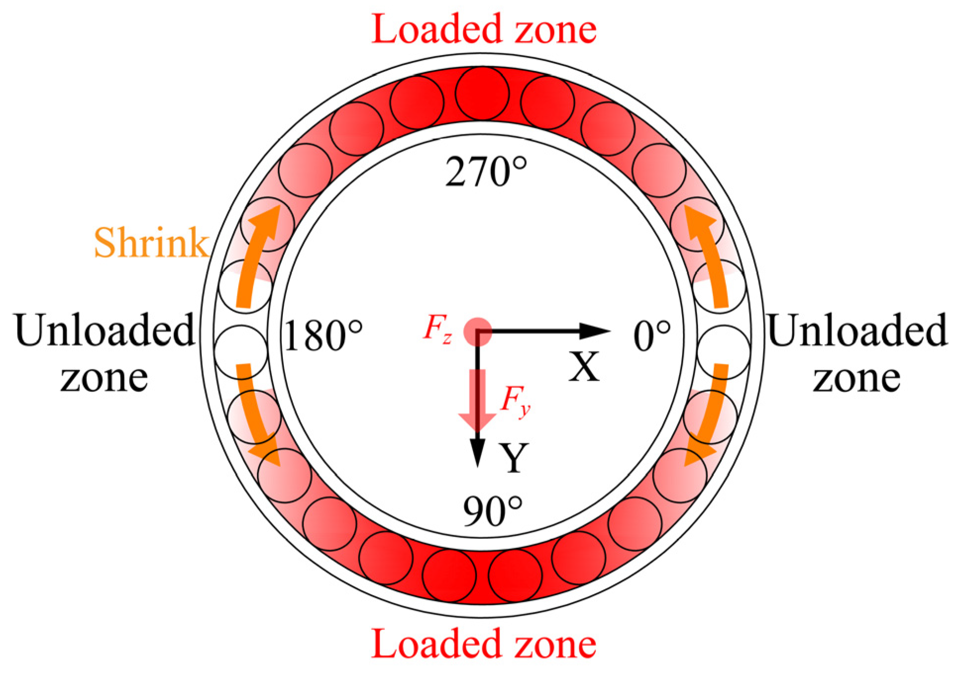
Figure 12 illustrates the effect of axial force on the outer ring deformation under constant radial force. Noticeable differences in ring deformation and variation tendency are observed between the vertical and horizontal directions. When under pure radial force, the ball–raceway contact loads concentrate in the 90° azimuth area, causing an expansion in the vertical diameter and a reduction in the horizontal diameter of the ring. As the axial force increases, the vertical diameter of the ring increases while the horizontal diameter decreases further. This is because the increase in the axial force causes the balls at the 270° azimuth angle area to be loaded, which in turn causes the vertical diameter of the ring to increase, while the unloaded zone in the horizontal area leads to a further decrease in the ring diameter. Figure 13 depicts the variation trend in the loaded zones under the action of axial force. When all the balls are loaded, the decrease in ring diameter tends to the maximum. However, with further increases in axial force, the horizontal diameter of the ring begins to increase. As seen in Figure 14, there is a critical axial force on the deformation curve of the horizontal diameter of the ring. The trend of ring deformation on both sides of the critical axial force is different, and the critical axial force values are variable. When the radial force is 3.1 kN, the critical axial force is 3 kN. Meanwhile, when the radial force is 3.5 kN and 3.9 kN, the critical axial force values change to 3.4 kN and 3.6 kN, respectively. As the radial force value increases, the critical axial force value increases. The primary reason is that a larger radial force makes a larger unloaded zone and a larger reduction in ring diameter in the horizontal direction at the same axial force. Therefore, a larger axial force is required to load the balls in the horizontal area and then change the tendency of ring deformation in that area.
Figure 15a indicates the influence of axial force on the ball–raceway contact state. As the axial force increases, more balls are gradually loaded until all balls are loaded. However, notable distinctions are observed between the rigid and flexible ring models in terms of the increasing trend and mutation position in the number of loaded balls. This is due to the ring deformation changing the radial clearance and the curvature of the raceway, making the ball and raceway easier to contact. The influence of axial force on the relative ratio of the maximum load is shown in Figure 15b. The relative ratio of the maximum load is defined as the maximum ball–raceway contact load in a flexible ring divided by that in a rigid ring. A smaller relative ratio corresponds to a smaller maximum contact load in the flexible ring, indicating a more pronounced optimization effect in load distribution due to the ring deformation. However, as the axial force increases, the relative ratio also rises, suggesting that the load optimization effect becomes less evident under higher axial force. This can be attributed to the increase in axial force reducing the difference between the ball–raceway contact loads, leading to the ring deformation tending to a standard circle, thus reducing the degree of load optimization. As axial force increases, the maximum contact stress initially decreases and then increases. This occurs because the increased number of loaded balls initially reduces contact stress. However, once all balls are loaded, the contact stress increases as the axial force increases. Figure 15c illustrates how the axial force affects the radial displacement of the inner ring. The displacement of the inner ring under flexible conditions is greater than that under rigid conditions. The reason is that under rigid conditions, the shaft and inner ring can only deflect at an angle to balance the external load. However, the bearing rings and supporting structures can also produce elastic deformation to balance the external load under flexible conditions [27]. Figure 15d shows the influence of axial force on ball–raceway contact angles. The contact angles near 90° azimuth increase with axial force, while the contact angles near 270° azimuth change conversely. Meanwhile, the contact angles near 90° azimuth are smaller than those in the rigid condition, while the contact angles near 270° azimuth are larger than those in the rigid condition.
3.4. The Effect of Radial Force
Figure 16 shows the influence of the radial force on the outer ring deformation under constant axial force. Under pure axial force, the ring deformation tends to be a standard circle. The reason is that all balls are loaded and exert almost the same force on the outer ring. As the radial force increases, the horizontal diameter of the ring continuously decreases while the vertical diameter increases. This is because the increase in radial force causes the concentration of the ball–raceway contact load in the vertical areas, resulting in an increase in the ring diameter in that direction, while the contact load in the horizontal direction decreases and eventually disappears, leading to a reduction in the ring diameter. Figure 17 illustrates the variation trend in the loaded zones under radial force.
Figure 18a demonstrates the effect of radial force on the bearing contact state. As the radial force increases, the radial clearance increases and the number of loaded balls decreases gradually. The decreasing trend and mutation position of the number of loaded balls under the rigid and flexible models are different, proving that the rigid ring model inadequately describes the contact state inside the thin-walled bearings. Figure 18b shows that the degree of load optimization becomes more pronounced under high radial force conditions. This phenomenon is because the increase in radial force intensifies the difference between ball–raceway contact loads, consequently enhancing ring deformation and optimizing load distribution. However, the increase in radial force results in a rise in the contact stress. After accounting for ring deformation, the ball–raceway contact angle increases, bringing the ball closer to the raceway rib and making the bearing more susceptible to elliptical truncation. Figure 18c shows that the radial displacement of the flexible inner ring is greater than that of the rigid inner ring. The cause behind this phenomenon mirrors that of the phenomenon depicted in Figure 15c, which is not explained here. However, it should be noted that the variance in displacement between the rigid and flexible rings increases alongside the increase in radial force. Compared with the flexible ring, the rigid ring only produces rigid displacement to balance the external load, but large rigid displacement leads to excessive ball–raceway contact load, which increases the error of accurately evaluating the bearing performance [19]. Figure 18d shows that the increase in radial force can decrease the contact angles near 90° azimuth and increase the contact angles near 270° azimuth. The effect of ring deformation on the contact angles parallels the discussion in Section 3.3.
3.5. The Effect of the Outer Ring Thickness
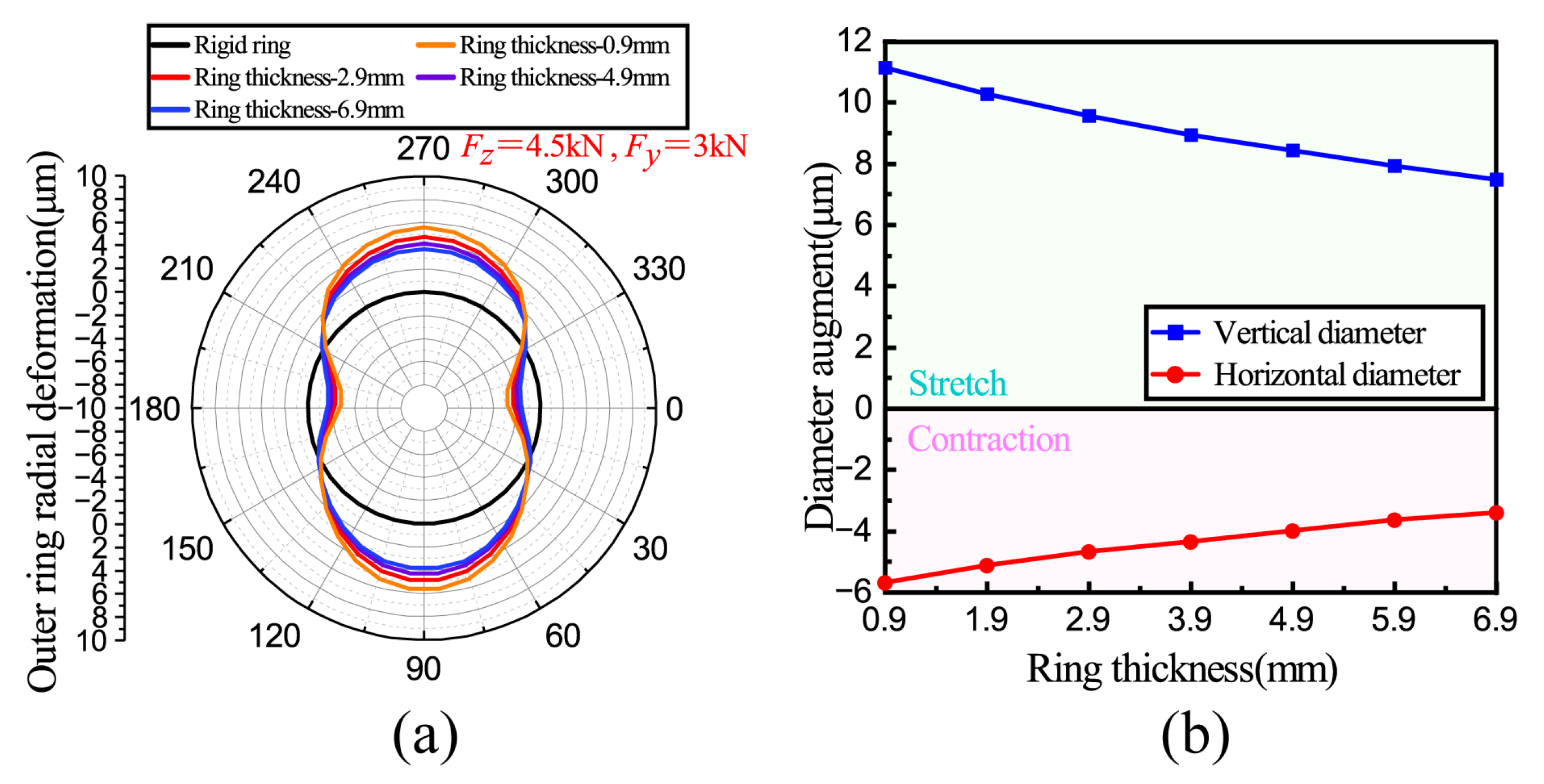
The influence of the outer ring thickness on the ring deformation is shown in Figure 19. It is evident that with the increase in ring thickness, both the horizontal and vertical diameters of the ring decrease. The ring thickness only affects the ring deformation and does not change the deformation trend of the ring. However, there is a significant distance between the fixed constraint surface of the reducer and the outer ring surface, and this distance leads to significant ring deformation, making it difficult for the ring to approximate a standard circle, even with larger ring thicknesses.
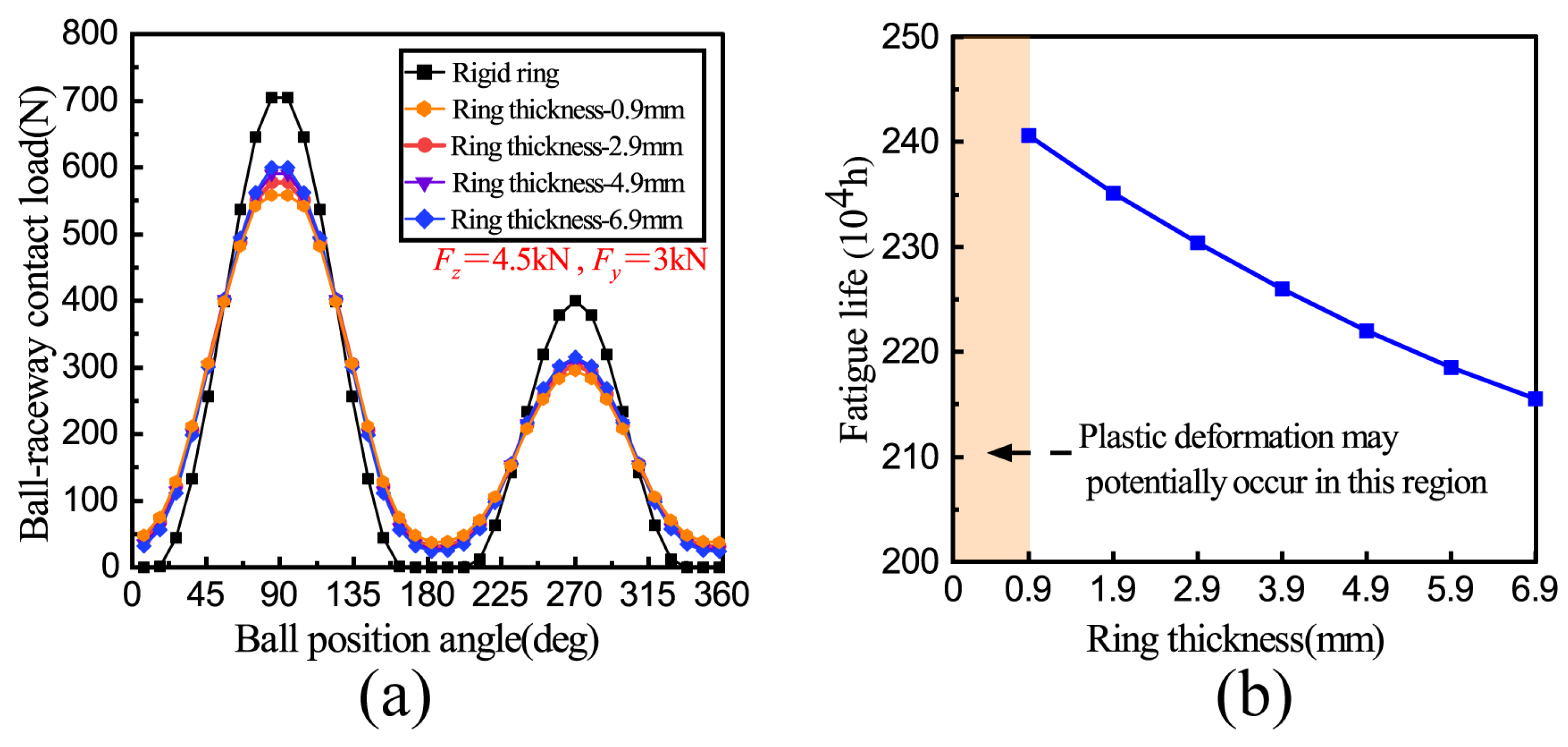
Figure 20a shows the number of loaded balls with different ring thicknesses, which increases from 29 under the rigid ring model to 37 under the flexible ring model. It can also be concluded that the thinner the ring thickness, the more the contact load is reduced, and the load optimization effect is more pronounced. However, the thinner ring thickness increases the failure risk of plastic deformation. The bearing fatigue life based on [28] was calculated, as shown in Figure 20b. The calculation equation of the bearing fatigue life is as follows:
where Ln is the bearing fatigue life modified by [28]; a1 is the reliability coefficient; a2 is the material coefficient, and a3 is the service condition coefficient. The fatigue life L10 is determined by the service life of the ball–raceway contact, which is calculated as follows [29]:
where Li and Lo are the contact life of the ball-inner raceway and the ball-outer raceway, respectively, and the calculation method is as follows:
where Ci,o is the basic dynamic load rating of the inner and outer raceway; Qi,o is the dynamic equivalent rolling element load of the inner and outer raceway, and the calculation method of Ci,o is as follows:
where Cr is the basic dynamic load rating of the bearing, which is calculated as follows:
where bm is the dynamic load coefficient; i is the number of the bearing rows; α is the bearing contact angle; Z is the number of balls; Dw is the diameter of the ball, and the expression of fc is
where γ is a dimensionless parameter with the expression
In this study, the outer ring is fixed while the inner ring rotates. Therefore, the calculation methods for Qi,o are as follows:
where Qik and Qok are the contact loads of the ball–inner raceway and ball–outer raceway, respectively, calculated by the mathematical model of the bearing.
It is evident that the fatigue life remains unaffected by variations in the thickness of the rigid ring. When considering ring deformation, the fatigue life decreases as the ring thickness increases. With the increase in ring thickness, the ring deformation gradually decreases. Consequently, the optimization effect of ring deformation on the load distribution gradually diminishes, resulting in a decrease in the number of loaded balls and an increase in the maximum ball–contact load under flexible ring conditions. According to Equations (30)–(32), the fatigue life decreases and becomes closer to the fatigue life of bearings with rigid rings. Due to the inability to fully simulate rigid constraints, it is difficult to achieve the same bearing life as the rigid ring model, even with larger ring thicknesses.
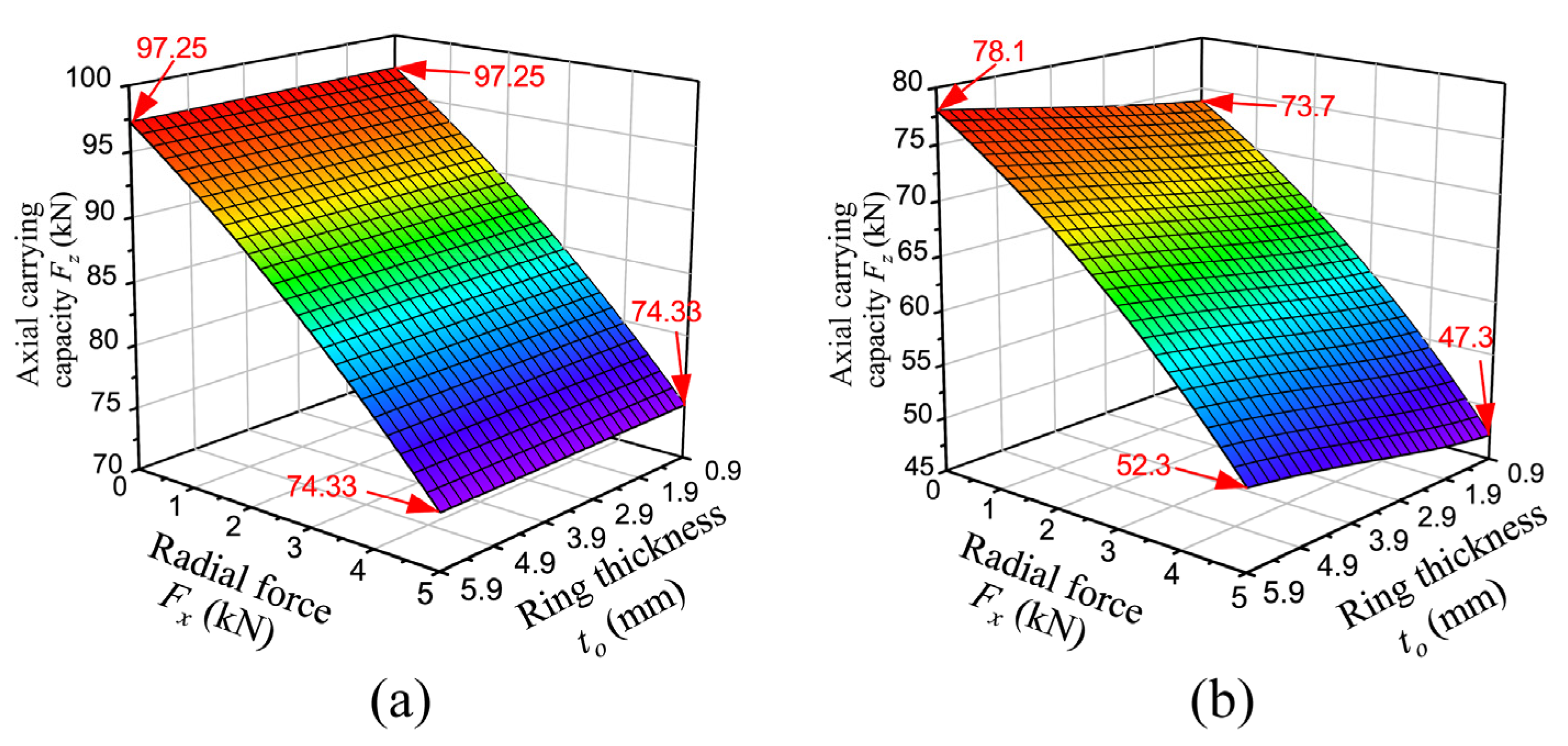
Figure 21 illustrates the axial ultimate carrying capacity of the thin-walled bearings under the influences of radial force and outer ring thickness. It is apparent that the carrying capacity decreases as the radial force increases. The increase in radial force promotes the movement of the contact ellipse toward the raceway rib, making it easier for the bearing to experience elliptical truncation under high radial force conditions. In addition, the thickness of the rigid ring does not affect the carrying capacity. However, the overall carrying capacity of the bearing decreases compared to that of the rigid condition after considering the ring deformation, and the carrying capacity decreases as the ring thickness decreases. From the above discussion, it is evident that while reducing the thickness of the ring can improve the optimization effect of the ring deformation on the contact load, it concurrently diminishes the carrying capacity. These results are difficult to obtain from the rigid ring model.
3.6. The Effect of Radial Clearance
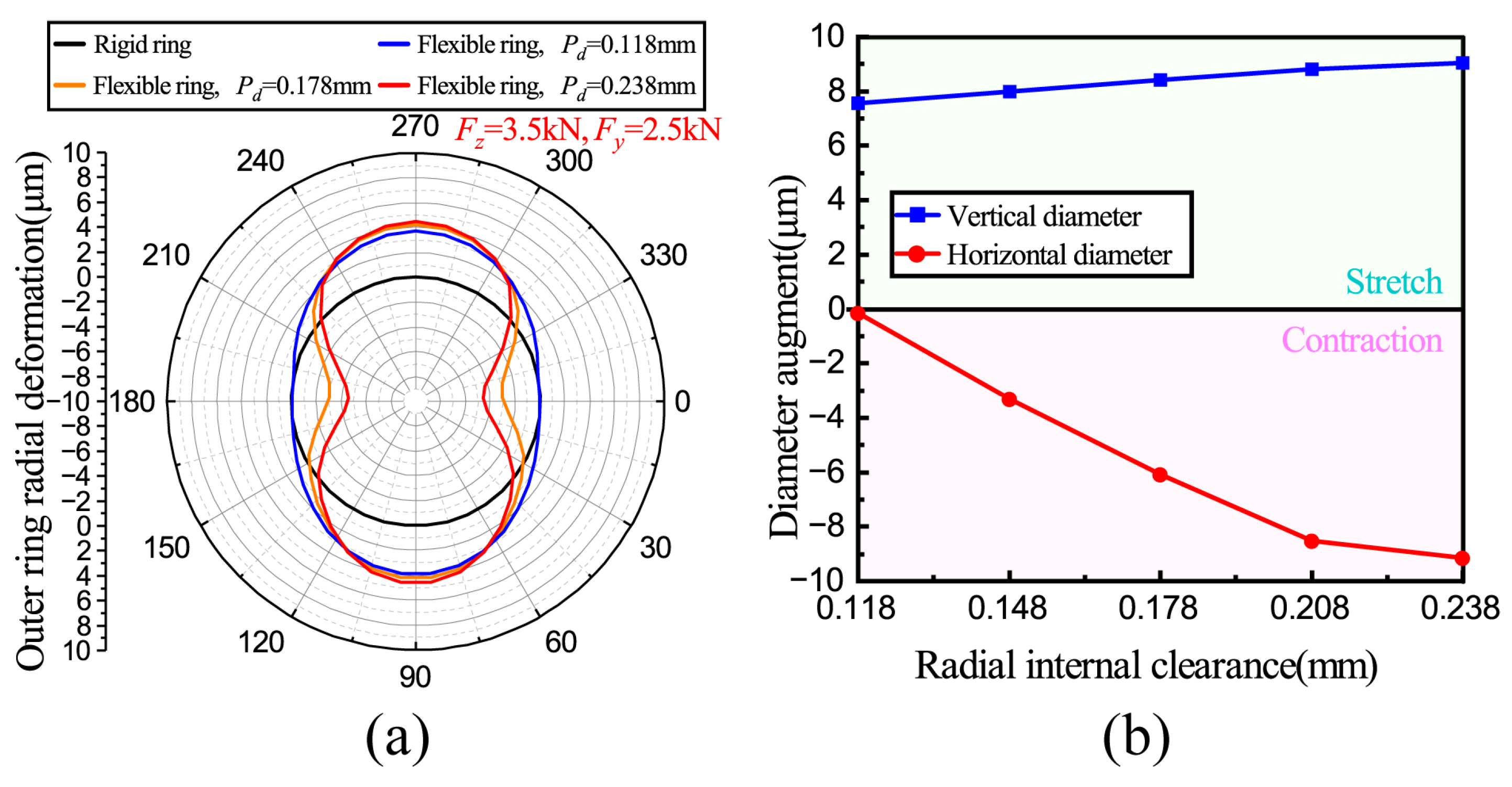
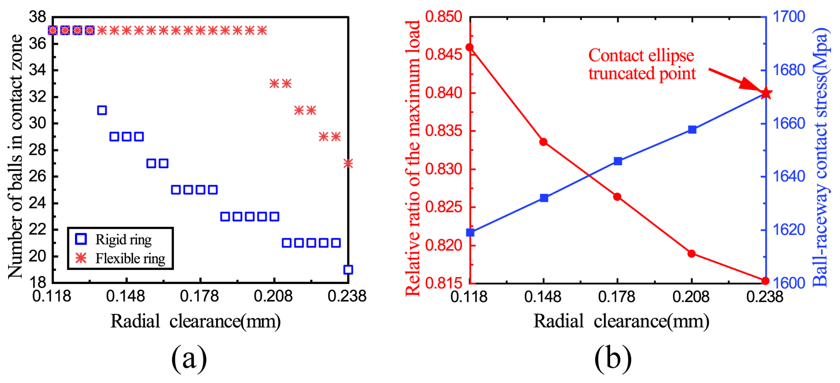
Figure 22 illustrates the effect of radial clearance on ring deformation. With increasing radial clearance, the vertical diameter of the ring increases while the horizontal diameter decreases, and the changing trend of the horizontal diameter is more significant than that of the vertical diameter. This is due to the fact that as the clearance increases, two unloaded zones appear in the horizontal direction, causing a swift reduction in the horizontal diameter of the ring. As shown in Figure 23a, it can be found that compared with the factors discussed above (axial and radial forces), the clearance exacerbates the distinction between the two models in terms of the ball–raceway contact state. Considering the ring deformation enables obtaining more accurate bearing contact characteristics. Figure 23b illustrates that the degree of load optimization improves as the clearance increases. However, this improvement comes at the expense of an increase in contact stress, ultimately leading to the truncation of the contact ellipse.
Figure 24 shows the influence of radial force and clearance on the axial ultimate carrying capacity of thin-walled bearings. The observed trend reveals that with the increment of radial force and radial clearance, there is a corresponding decrement in the axial ultimate carrying capacity. Considering the ring deformation, the maximum reduction in carrying capacity is 38.2%, which occurs under the condition of maximum radial force and maximum radial clearance. In this condition, the ring deformation is most pronounced; the ball–raceway contact angle is greater, and the ball is closer to the raceway rib. It is worth mentioning that compared with the rigid ring model, the axial carrying capacity of the flexible ring model shows a higher sensitivity to the radial force and clearance, which can be observed in the trend of carrying capacity. Therefore, the clearance can be moderately increased to enhance the degree of load optimization, but attention should be paid to excessive contact stresses and the occurrence of elliptical truncation phenomena.
4. Conclusions
According to the actual assembly structure of the main bearing for the RV reducer, a simulation model of the planetary frame–main bearings–pin gear housing, which can fully consider the elastic deformation, is established in this paper. The validity of the proposed model is confirmed by comparing its results with those obtained from conventional methods. The effects of load conditions, ring thickness, and clearance on ring deformation, ball–raceway contact state, the relative ratio of the maximum load, and the ultimate carrying capacity are analyzed, respectively. The significant findings are as follows:
- (1)
- Ring deformation cannot be ignored in the analysis of thin-walled bearings. The distribution of ball–raceway contact loads determines both the extent and the trend of ring deformation. Ring deformation can improve the mechanical characteristics and extend the fatigue life of bearings. However, the ring deformation makes the ball–raceway contact ellipse closer or even exceeds the raceway rib, leading to ellipse truncation. Therefore, focusing on the raceway rib design is crucial when designing thin-walled bearings;
- (2)
- The optimization effect of ring deformation on load distribution varies under different conditions. The increase in axial force and ring thickness weakens this optimization effect, while the increase in radial force and clearance enhances it but also results in an increase in contact stress. In actual engineering, bearing engineers can design ring thickness, clearance, and the raceway rib reasonably according to the research results of this paper and improve the optimization effect of ring deformation on load distribution and fatigue life without plastic deformation of bearings to improve the service performance of bearings effectively;
- (3)
- Significant differences are observed in the variation trends and mutation positions in the number of loaded balls between the rigid and flexible ring models, resulting in substantial differences in the contact characteristics of the two models under the same load condition;
- (4)
- After considering the ring deformation, the carrying capacity of the bearing decreases, with a heightened sensitivity to radial force and radial clearance. In this research, the maximum carrying capacity was reduced by 38.2%, which occurred by coupling the maximum radial force and the maximum clearance.
Author Contributions
Conceptualization, Y.W. and F.L.; methodology, Y.W. and F.L.; software, Y.W. and F.L.; validation, Y.W. and F.L.; formal analysis, Y.W. and F.L.; investigation, Y.W. and F.L.; resources, Y.W. and F.L.; data curation, Y.W. and F.L.; writing—original draft preparation, Y.W. and F.L.; writing—review and editing, Y.W. and F.L.; visualization, Y.W. and F.L.; supervision, Y.W.; project administration, Y.W.; funding acquisition, Y.W. All authors have read and agreed to the published version of the manuscript.
Funding
This research was funded by the National Natural Science Foundation of China (Grant No. 52075274); the Shandong Province focuses on supporting regions to introduce urgently needed talent projects (Grant No. 2023JXJQRC), the Liaocheng City Major Science and Technology Innovation Project (Grant No. 2021ZD04), and the Shandong Province science and technology innovation ability improvement project for small and medium-sized enterprises (Grant No. 2023TSGC0356, 2023TSGC0374).
Institutional Review Board Statement
Not applicable.
Informed Consent Statement
Not applicable.
Data Availability Statement
Data is contained within the article.
Acknowledgments
The authors would like to express their appreciation to the anonymous reviewers for their help and meaningful comments on this paper.
Conflicts of Interest
The authors declare no conflicts of interest.
References
- Pham, A.-D.; Ahn, H.-J. High precision reducers for industrial robots driving 4th industrial revolution: State of arts, analysis, design, performance evaluation and perspective. Int. J. Precis. Eng. Manuf.-Green Technol. 2018, 5, 519–533. [Google Scholar] [CrossRef]
- Hong, S.W.; Tong, V.C. Rolling-element bearing modeling: A review. Int. J. Precis. Eng. Manuf. 2016, 17, 1729–1749. [Google Scholar] [CrossRef]
- Zhang, J.; Fang, B.; Hong, J.; Zhu, Y. Effect of preload on ball-raceway contact state and fatigue life of angular contact ball bearing. Tribol. Int. 2017, 114, 365–372. [Google Scholar] [CrossRef]
- Xie, Y.; Xu, L.; Deng, Y. A dynamic approach for evaluating the moment rigidity and rotation precision of a bearing-planetary frame rotor system used in RV reducer. Mech. Mach. Theory 2022, 173, 104851. [Google Scholar] [CrossRef]
- Deng, F.; Li, K.; Hu, X.; Jiang, H.; Huang, F. Life calculation of angular contact ball bearings for industrial robot RV reducer. Ind. Lubr. Tribol. 2019, 71, 826–831. [Google Scholar] [CrossRef]
- Göncz, P.; Potočnik, R.; Glodež, S. Computational model for determination of static load capacity of three-row roller slewing bearings with arbitrary clearances and predefined raceway deformations. Int. J. Mech. Sci. 2013, 73, 82–92. [Google Scholar] [CrossRef]
- Li, Y. Effects of design parameters on carrying capacity of a double-row tapered roller slewing bearing used in wind turbine. Adv. Mech. Eng. 2016, 8, 1–10. [Google Scholar] [CrossRef]
- Li, Y.; Jiang, D. Dynamic carrying capacity analysis of double-Row four-Point contact ball slewing bearing. Math. Probl. Eng. 2015, 2015, 850908. [Google Scholar] [CrossRef]
- Pathuvoth, D.; Sekhar, A.S. Static capacity of slewing bearings considering ellipse truncation. Tribol. Int. 2022, 173, 107595. [Google Scholar] [CrossRef]
- Harris, T.A.; Kotzalas, M.N. Advanced Concepts of Bearing Technology Rolling Bearing Analysis; CRC Press: Boca Raton, FL, USA; Taylor Francis Group: New York, NY, USA, 2006. [Google Scholar]
- Xu, H.; Wang, P.; Ma, H.; He, D.; Zhao, X.; Yang, Y. Analysis of axial and overturning ultimate load-bearing capacities of deep groove ball bearings under combined loads and arbitrary rotation speed. Mech. Mach. Theory 2022, 169, 104665. [Google Scholar] [CrossRef]
- Wang, S.; Du, J.; Chen, Y.; Wu, S.; Huang, Z. Influence of elliptical truncation on the raceway in a four-point contact pitching bearing. Eng. Fail. Anal. 2022, 141, 106711. [Google Scholar] [CrossRef]
- Gao, X.; Huang, X.; Wang, H.; Hong, R.; Chen, J. Effect of raceway geometry parameters on the carrying capability and the service life of a four-point-contact slewing bearing. J. Mech. Sci. Technol. 2010, 24, 2083–2089. [Google Scholar] [CrossRef]
- He, P.; Qian, Q.; Wang, Y.; Liu, H.; Guo, E.; Wang, H. Influence of finite element mesh size on the carrying capacity analysis of single-row ball slewing bearing. Adv. Mech. Eng. 2021, 13, 1–12. [Google Scholar] [CrossRef]
- Olave, M.; Sagartzazu, X.; Damian, J.; Serna, A. Design of four contact-point slewing bearing with a new load distribution procedure to account for structural stiffness. J. Mech. Des. 2010, 132, 021006. [Google Scholar] [CrossRef]
- Yan, K.; Hong, J.; Zhang, J.; Mi, W.; Wu, W. Thermal-deformation coupling in thermal network for transient analysis of spindle-bearing system. Int. J. Therm. Sci. 2016, 104, 1–12. [Google Scholar] [CrossRef]
- Harris, T.A.; Broschard, J.L. Analysis of an improved planetary gear-transmission bearing. J. Basic Eng. 1964, 86, 457–461. [Google Scholar] [CrossRef]
- Cavallaro, G.; Nelias, D. Analysis of high-speed intershaft cylindrical roller bearing with flexible rings. Tribol. Trans. 2005, 48, 154–164. [Google Scholar] [CrossRef]
- Wagner, C.; Krinner, A.; Thümmel, T.; Rixen, D. Full dynamic ball bearing model with elastic outer ring for high speed applications. Lubricants 2017, 5, 17. [Google Scholar] [CrossRef]
- Liu, J.; Tang, C.; Shao, Y. An innovative dynamic model for vibration analysis of a flexible roller bearing. Mech. Mach. Theory 2019, 135, 27–39. [Google Scholar] [CrossRef]
- Hao, X.; Gu, X.; Zhou, X.; Liao, X.; Han, Q. Distribution characteristics of stress and displacement of rings of cylindrical roller bearing. Proc. Inst. Mech. Eng. Part C J. Mech. Eng. Sci. 2019, 233, 4348–4358. [Google Scholar] [CrossRef]
- Mao, Y.; Wang, L.; Zhang, C. Influence of ring deformation on the dynamic characteristics of a roller bearing in clearance fit with housing. Int. J. Mech. Sci. 2018, 138–139, 122–130. [Google Scholar] [CrossRef]
- Wang, M.; Yan, K.; Zhang, X.; Zhu, Y.; Hong, J. A comprehensive study on dynamic performance of ball bearing considering bearing deformations and ball-inner raceway separation. Mech. Syst. Signal Proc. 2023, 185, 109826. [Google Scholar] [CrossRef]
- Wang, M.; Yan, K.; Tang, Q.; Guo, J.; Zhu, Y.; Hong, J. Dynamic modeling and properties analysis for ball bearing driven by structure flexible deformations. Tribol. Int. 2023, 179, 108163. [Google Scholar] [CrossRef]
- Yao, T.; Chi, Y.; Huang, Y. Research on flexibility of bearing rings for multibody contact dynamics of rolling bearings. Procedia Eng. 2012, 31, 586–594. [Google Scholar] [CrossRef]
- Chen, G.; Wen, J. Load performance of large-scale rolling bearings with supporting structure in wind turbines. J. Tribol. 2012, 134, 041105. [Google Scholar] [CrossRef]
- Liu, X.; Niu, R.; Wang, B.; Zhang, S.; Cui, Y.; Zhang, Z. Crowning method on bearing supporting large wind turbine spindle considering the flexibility of structure of shaft system. Machines 2023, 11, 28. [Google Scholar] [CrossRef]
- ISO 281:2007; Rolling Bearings—Dynamic Load Ratings and Rating Life. International Organization for Standardization: Geneva, Switzerland, 2007.
- Lundberg, G.; Palmgren, A. Dynamic Capacity of Rolling Bearings. J. Appl. Mech. 1949, 16, 165–172. [Google Scholar] [CrossRef]
Figure 1.
The position relationships between the ball center and the raceway curvature centers.

Figure 2.
Effect of ring elastic deformation on ball–raceway contact deformation.

Figure 3.
The force and displacement of the ring.

Figure 4.
Flowchart of the solution process for the simulation model.

Figure 5.
Ellipse truncation.

Figure 6.
The RV reducer.

Figure 7.
Flexible ring model.

Figure 8.
Comparison of results between the flexible and rigid ring hypothesis models: (a) ring deformation; (b) ball–raceway contact loads.
Figure 8.
Comparison of results between the flexible and rigid ring hypothesis models: (a) ring deformation; (b) ball–raceway contact loads.

Figure 9.
Horizontal and vertical areas of the bearing.

Figure 10.
Ring deformation: (a) left bearing; (b) right bearing.

Figure 11.
Effect of ring deformation on contact characteristics: (a) ball–raceway contact load of the left bearing; (b) ball–raceway contact load of the right bearing; (c) contact angles of the left bearing; (d) contact angles of the right bearing.
Figure 11.
Effect of ring deformation on contact characteristics: (a) ball–raceway contact load of the left bearing; (b) ball–raceway contact load of the right bearing; (c) contact angles of the left bearing; (d) contact angles of the right bearing.

Figure 12.
Effect of axial force on ring deformation: (a) ring deformation; (b) diameter augment.

Figure 13.
Effect of axial force on variation trend in loaded zones.

Figure 14.
Effect of axial force on the ring horizontal diameter.

Figure 15.
Effect of axial force on contact characteristics: (a) number of loaded balls; (b) the relative ratio of the maximum load and ball–raceway contact stress; (c) radial displacements of the inner ring; (d) ball–raceway contact angles.
Figure 15.
Effect of axial force on contact characteristics: (a) number of loaded balls; (b) the relative ratio of the maximum load and ball–raceway contact stress; (c) radial displacements of the inner ring; (d) ball–raceway contact angles.

Figure 16.
Effect of radial force on ring deformation: (a) ring deformation; (b) diameter augment.

Figure 17.
Effect of radial force on variation trend in loaded zones.

Figure 18.
Effect of radial force on contact characteristics: (a) number of loaded balls; (b) the relative ratio of the maximum load and ball–raceway contact stress; (c) radial displacements of the inner ring; (d) ball–raceway contact angles.
Figure 18.
Effect of radial force on contact characteristics: (a) number of loaded balls; (b) the relative ratio of the maximum load and ball–raceway contact stress; (c) radial displacements of the inner ring; (d) ball–raceway contact angles.

Figure 19.
Effect of the ring thickness on ring deformation: (a) ring deformation; (b) diameter augment.
Figure 19.
Effect of the ring thickness on ring deformation: (a) ring deformation; (b) diameter augment.

Figure 20.
Influence of the outer ring thickness on contact loads and fatigue life: (a) contact loads; (b) fatigue life.
Figure 20.
Influence of the outer ring thickness on contact loads and fatigue life: (a) contact loads; (b) fatigue life.

Figure 21.
Effect of the outer ring thickness on carrying capacity: (a) rigid ring model; (b) flexible ring model.
Figure 21.
Effect of the outer ring thickness on carrying capacity: (a) rigid ring model; (b) flexible ring model.

Figure 22.
Effect of radial clearance on ring deformation: (a) ring deformation; (b) diameter augment.
Figure 22.
Effect of radial clearance on ring deformation: (a) ring deformation; (b) diameter augment.

Figure 23.
Effect of radial clearance on contact characteristics: (a) number of loaded balls; (b) the relative ratio of the maximum load and ball–raceway contact stress.
Figure 23.
Effect of radial clearance on contact characteristics: (a) number of loaded balls; (b) the relative ratio of the maximum load and ball–raceway contact stress.

Figure 24.
Effect of the radial clearance on carrying capacity: (a) rigid ring model; (b) flexible ring model.
Figure 24.
Effect of the radial clearance on carrying capacity: (a) rigid ring model; (b) flexible ring model.


Table 1.
Geometry parameters of the thin-walled angular contact ball bearing.
| Parameter | Value |
|---|---|
| Inner race diameter (mm) | 115 |
| Outer race diameter (mm) | 145 |
| Curvature coefficient of the inner raceway | 0.525 |
| Curvature coefficient of the outer raceway | 0.515 |
| Ball diameter (mm) | 9.525 |
| Ball number | 37 |
| Bearing width (mm) | 15 |
| Number of bolt holes | 16 |
| Pitch diameter (mm) | 130 |
| Pitch diameter of bolt hole (mm) | 175 |
| Left rib height of inner raceway (mm) | 3.746 |
| Right rib height of outer raceway (mm) | 4.319 |
| Bearing initial contact angel (°) | 40 |
Table 2.
Material parameters of the thin-walled angular contact ball bearing.
| Component | Modulus of Elasticity E (GPa) | Poisson’s Ratio ν | Density ρ (kg/m3) |
|---|---|---|---|
| Planetary frame | 210 | 0.29 | 7850 |
| Inner and outer ring | 205 | 0.3 | 7806 |
| Ball | 203 | 0.29 | 7810 |
| Pin gear housing | 169 | 0.286 | 7120 |
Disclaimer/Publisher’s Note: The statements, opinions and data contained in all publications are solely those of the individual author(s) and contributor(s) and not of MDPI and/or the editor(s). MDPI and/or the editor(s) disclaim responsibility for any injury to people or property resulting from any ideas, methods, instructions or products referred to in the content. |
© 2024 by the authors. Licensee MDPI, Basel, Switzerland. This article is an open access article distributed under the terms and conditions of the Creative Commons Attribution (CC BY) license (https://creativecommons.org/licenses/by/4.0/).
Share and Cite
MDPI and ACS Style
Wang, Y.; Liu, F. Study on Ring Deformation and Contact Characteristics of Thin-Walled Bearing for RV Reducer. Appl. Sci. 2024, 14, 3741. https://0-doi-org.brum.beds.ac.uk/10.3390/app14093741
AMA Style
Wang Y, Liu F. Study on Ring Deformation and Contact Characteristics of Thin-Walled Bearing for RV Reducer. Applied Sciences. 2024; 14(9):3741. https://0-doi-org.brum.beds.ac.uk/10.3390/app14093741
Chicago/Turabian StyleWang, Yanshuang, and Fangzheng Liu. 2024. "Study on Ring Deformation and Contact Characteristics of Thin-Walled Bearing for RV Reducer" Applied Sciences 14, no. 9: 3741. https://0-doi-org.brum.beds.ac.uk/10.3390/app14093741
Note that from the first issue of 2016, this journal uses article numbers instead of page numbers. See further details here.