Article

Prediction and Optimization of Heat Transfer Performance of Premixed Methane Impinging Flame Jet Using the Kriging Model and Genetic Algorithm

1
Department of Aeronautics and Astronautics, National Cheng Kung University, Tainan 701401, Taiwan
2
Department of Statistics, National Cheng Kung University, Tainan 701401, Taiwan
3
Institute of Data Science, National Cheng Kung University, Tainan 701401, Taiwan
*
Author to whom correspondence should be addressed.
Submission received: 30 March 2024 / Revised: 24 April 2024 / Accepted: 25 April 2024 / Published: 27 April 2024
(This article belongs to the Topic Applied Heat Transfer)

Abstract

:
In practical applications, rapid prediction and optimization of heat transfer performance are essential for premixed methane impinging flame jets (PMIFJs). This study uses computational fluid dynamics (CFD) combined with a methane detailed chemical reaction mechanism (GRI–Mech 3.0) to study the equivalence ratio ( ϕ ), Reynolds number ( R e ) of the mixture, and the normalized nozzle–to–plate distance ( H / d ) on the heat transfer performance of PMIFJs. Moreover, the Kriging model (KM) was used to construct a prediction model of PMIFJ heat transfer performance. A genetic algorithm (GA) was used to determine the maximum likelihood function (MLE) of the model parameters for constructing KM and identify the points with the maximum root mean square error (RMSE) as the new infilled points for surrogate–based optimization (SBO). Combining these methods to analyze the simulation results, the results show that the global heat transfer performance of PMIFJs is enhanced with the increase in ϕ , the increase in R e , and the decrease in H / d . Sensitivity analysis points out that R e and ϕ significantly affect enhanced heat transfer, while H / d has a relatively small effect. In addition, GA was also used to search for the optimal heat transfer performance, and the global heat transfer performance at specific conditions was significantly enhanced. This study deepens the understanding of the heat transfer mechanism of impinging flame jets and provides an efficient method framework for practical applications.

1. Introduction

The impinging flame jet (IFJ) is applied in many domestic and industrial heating systems because of its high heat and mass transfer characteristics and importance in many practical applications [1], such as domestic cooking and heating, gas geysers, boiler wall heating, glass processing, and melting scrap metal parts [2]. IFJ can provide local heating, has short start–up and cool–down times, and can obtain greater heat flux than high–cost radiant heating technology [3]. Therefore, its primary fuel demand is less, its overall efficiency is improved, and it can even reduce pollutant emissions [4]. Finally, IFJ has become a very attractive alternative. As a result, many researchers have conducted experimental and numerical research on flame jet heat transfer (FJHT) to help comprehensively understand its thermal characteristics and provide valuable insights [5,6,7,8].
In general, the structure of IFJ can be divided into a free jet region, a stagnation region, and a wall jet region. Each region has different flow, combustion, and heat transfer characteristics. The mechanism of FJHT mainly consists of several complex physical and chemical processes, including thermal conduction, convection, radiation, condensation and boiling, and thermochemical heat release (TCHR) [9]. Therefore, its heat transfer process is much more complex than traditional isothermal impact jets. According to previous research reports, IFJ mainly uses forced convection as the heat transfer mechanism [10]. Previous studies have confirmed that in impinging flame jets that use air as the oxidant, forced convection heat transfer accounts for 70% to 90% of the total heat transfer in the impinging region [11,12]. The thermal radiation from the flame can be ignored since the emissivity of the hot gas layer is very low [13]. Cremer et al. [14] pointed out that the TCHR mechanism is significant in hydrocarbon fuel flames under pure oxygen or oxygen–rich conditions and can reach up to 60% of the total heat transfer. However, the effect on heat transfer in premixed methane–air flames is minimal and, therefore, can be ignored. In addition, the interaction between the flame and the wall produces flame structures with different characteristics depending on the position of the collision flame [15,16], and it plays a critical role in the near–wall combustion process of various combustion equipment and power engines [17,18].
Many parameters affect the heat transfer performance of IFJs. These include the geometry and design of the burner, the flame type, the operating conditions (fuel composition, Reynolds number of the jet, and the equivalence ratio of the mixture), and the distance of nozzle–to–plate. Chander and Ray [19] studied the influence of different burner geometries (tube, nozzle, and orifice) on the heat transfer characteristics of IFJs. It was found that the heat flux in the stagnation and wall jet regions is different, resulting in different flame lengths and shapes due to different exit velocity profiles. Compared to the heat flux distribution of the nozzle and orifice burner, the tube burner is non–uniform. Milson and Chigier [20] studied the heat transfer characteristics of diffusion and premixed methane flame impingement on cold steel plates. Compared with diffusion flame, the maximum heat flux of premixed flame is higher because premixed flames can increase the combustion rate and promote faster combustion completion. Hargrave et al. [21] indicated that as the Reynolds number increases, the reaction region of the premixed methane flame will extend further downstream and become wider. For the premixed methane impinging flame jet (PMIFJ), the peak heat flux is located near the reaction region, and both the velocity and temperature are found to reach the highest values in this region. This is due to the diffusion and exothermic recombination of dissociated substances in the boundary layer around the heated object, raising the convective heat transfer rate and heat flux [22]. Kwok [23] studied the effects of Reynolds number and equivalence ratio on premixed butane IFJs at a fixed nozzle–to–plate distance. The results indicate that the heat transfer to the impingement plate increases with the Reynolds number due to the turbulence enhancing the mixing of fuel and air, increasing the combustion rate. Furthermore, it is found that maximum heat transfer occurs under slightly fuel–rich conditions. Finally, it is proposed to match the flame length to the distance from the nozzle to the plate, which is crucial for achieving optimal heat transfer. Kuntikana and Prabhu [24] experimentally studied the heat transfer performance of PMIFJs. The thermal efficiency was found to increase with increasing Reynolds number and equivalence ratio. The thermal efficiency decreases as the distance of nozzle–to–plate increases. They also established an empirical correlation between the stagnation point Nusselt number and three parameters (Reynolds number, equivalence ratio, and nozzle–to–plate distance). The maximum deviation is 12% compared to the experimental stagnation point Nusselt number. Dong et al. [25] conducted experiments using premixed butane IFJs to establish empirical correlations between the average Nusselt number and Reynolds number, equivalence ratio, and nozzle–to–plate distance. Compared with the experimental average Nusselt number, the maximum deviation is 13.3%.
In addition to using experimental methods for research, numerical simulation methods can provide an augmented understanding of the correlation between the flow field and heat transfer of IFJs. Chander and Ray [26] used the computational fluid dynamics (CFD) method and simplified methane chemical reaction mechanisms to study the flow field and heat transfer characteristics of PMIFJs. The results show that the local peak heat flux is away from the stagnation region, which is caused by the change of the peak axial velocity close to the plate. Hidasageri et al. [27] studied PMIFJs produced by square and rectangular burners through CFD and a simplified methane chemical reaction mechanism. The simulated results show that the vortices formed near the corner of the tube produce an axis-switching phenomenon, causing the heat flux distribution on the impingement plate to be rotated. Singh et al. [28,29] adopted the CFD and a methane–air two–step global reaction mechanism to simulate the behavior of the flow field and heat transfer of several double-swirling flames impinging a flat plate without simplifying complex geometries and gain insights into their correlations. Laguillo et al. [30] used the CFD and the detailed chemical reaction mechanism of methane (GRI–Mech 3.0) to accurately capture the relevant phenomena that occur in the partially premixed flame of methane, such as the jet’s velocity decay, the structure of inner premixed cone and diffusion zone, the temperature distribution on the wall, and pollutants emission. It further provides the factual standard for the design of natural gas burners. Numerical simulation has become an indispensable part of today’s engineering. It provides a powerful tool that enables engineers to evaluate and analyze various engineering systems and processes more quickly and effectively [31,32]. CFD is commonly utilized to optimize the design and operating parameters of practical engineering problems [33,34,35]. However, the difficulties in CFD optimization are high computational costs and time constraints due to the need to consider the complexity of the geometry, the number of meshes, the applicability of the model, and the complexity of the chemical reaction mechanism.
Surrogate models are proposed as solutions to solve the above problems of CFD optimization. Therefore, this method is called surrogate–based optimization (SBO). Common surrogate models include the response surface method (RSM) [36], support vector regression (SVR) [37], radial basis function (RBF) [38], and Kriging model (KM) [39]. In these surrogate models, KM takes values from regionalized variables in finite regions and makes optimal and unbiased estimates from the perspective of the correlation and variability of variables. In addition, KM provides predicted mean and variance and establishes various learning functions to estimate failure probability and uncertainty accurately. Therefore, compared with other models, KM has higher fitting accuracy and can better approximate complex functions [40,41,42]. Surrogate models must cautiously be used due to the possible impact of new errors, although they can quickly obtain analytical results. Hence, the suitability of surrogate models must be carefully evaluated to ensure valid and accurate results, allowing for correct decisions to be made [43].
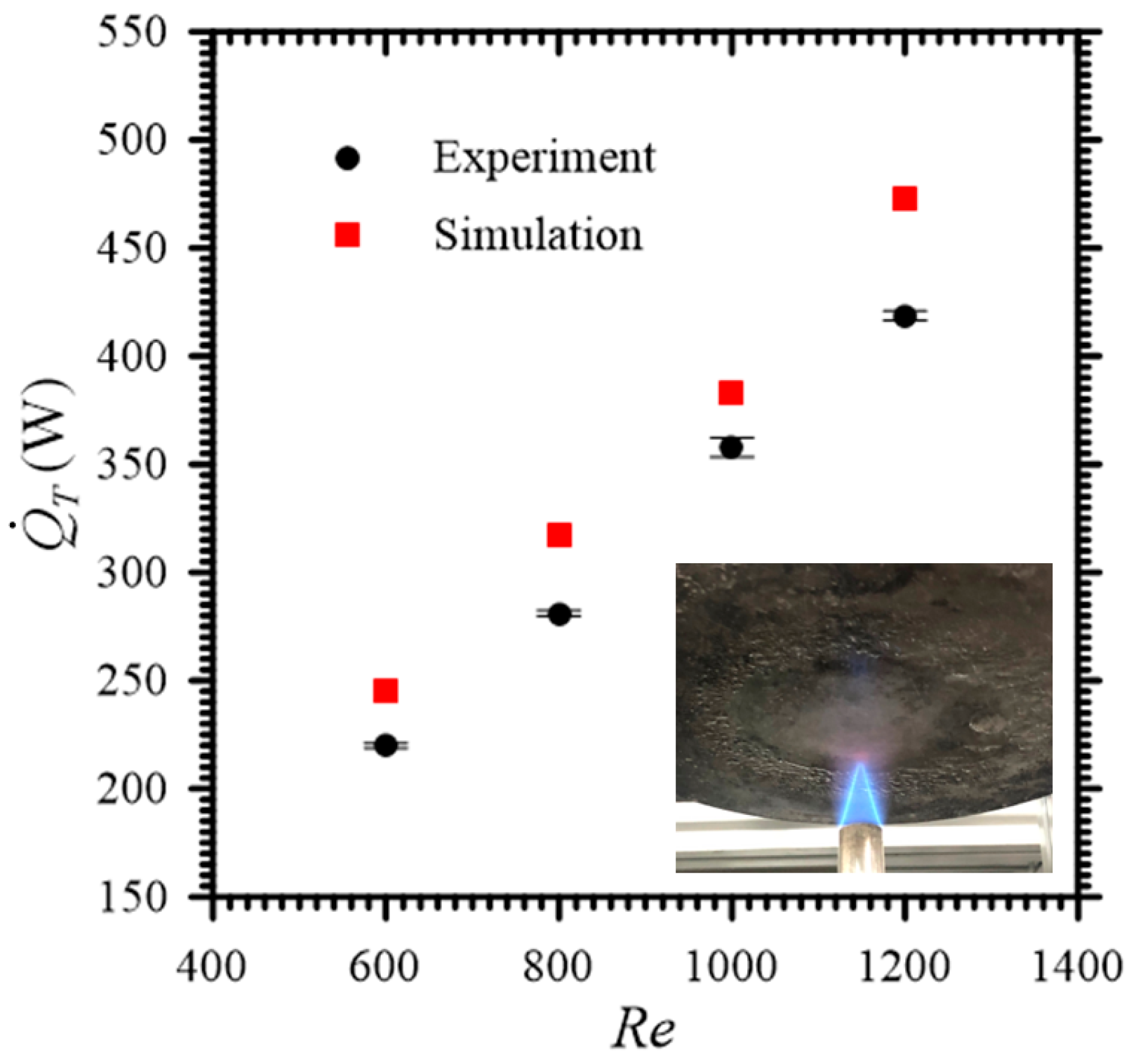
According to the previous literature review, empirical correlation was used to predict the heat transfer performance of unknown points for IFJs in the past, and the predicted values were found to deviate significantly from the actual values. In addition, since the optimization method for the heat transfer performance of IFJs has yet to be given, the optimal operating parameters of PMIFJs are worth exploring. This study uses experimental and numerical simulation methods to study PMIFJs. This study used the equivalence ratio, Reynolds number, and nozzle–to–plate distance, which are common in the previous literature, as research parameters. The experimental data serve as a validation of the numerical simulation to ensure its reliability. In terms of numerical simulation, obtaining the global heat transfer behavior and optimal solution using the CFD method and the detailed GRI–Mech 3.0 mechanism is quite challenging because of the complexity of the mechanism and the large number of computational resources required to consider all three parameters. Therefore, the SBO method is used to solve this problem, which is also the main contribution of this paper.
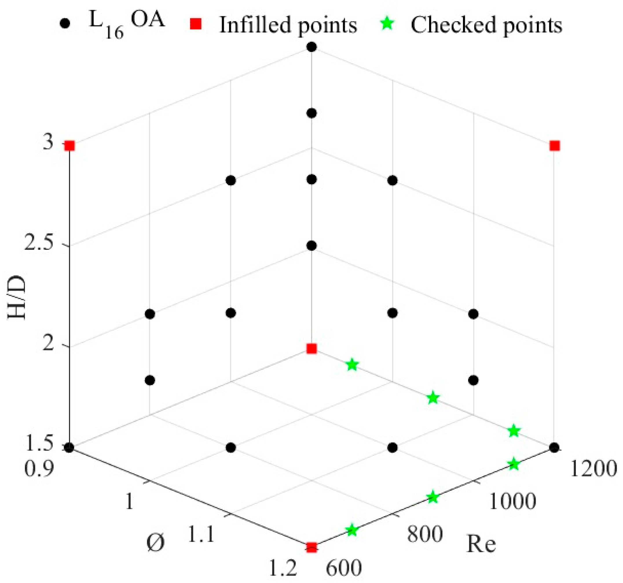
The KM is chosen as the surrogate model. Its Gaussian basis function has independently different variance values in different dimensions, which enables the model to capture changes in the parameter space more accurately, thereby obtaining more accurate and optimized response surfaces. Hence, global information within specific parameters can be gained by fewer simulations, and target values at unknown parameters can be further predicted. Furthermore, the genetic algorithm (GA) is used to determine three optimization problems: maximizing the likelihood function in KM, the new infilled points according to maximizing root mean square error (RMSE), and the operating parameters of optimal heat transfer performance.
The subsequent sections of this paper are structured as follows. Section 2 introduces the experimental setup and measurement methods. 
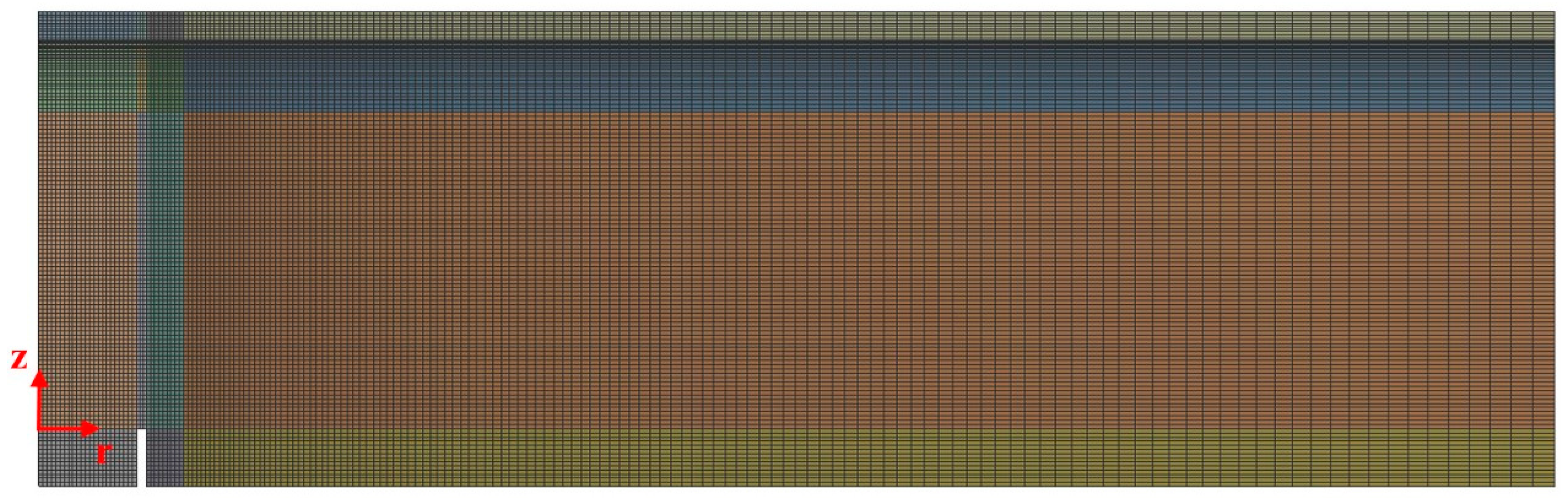
Section 3 provides the working process of the CFD method, mesh independence testing, and model validation results. Section 4 introduces the principles and working process of the SBO method and further elaborates on the details of each process. 
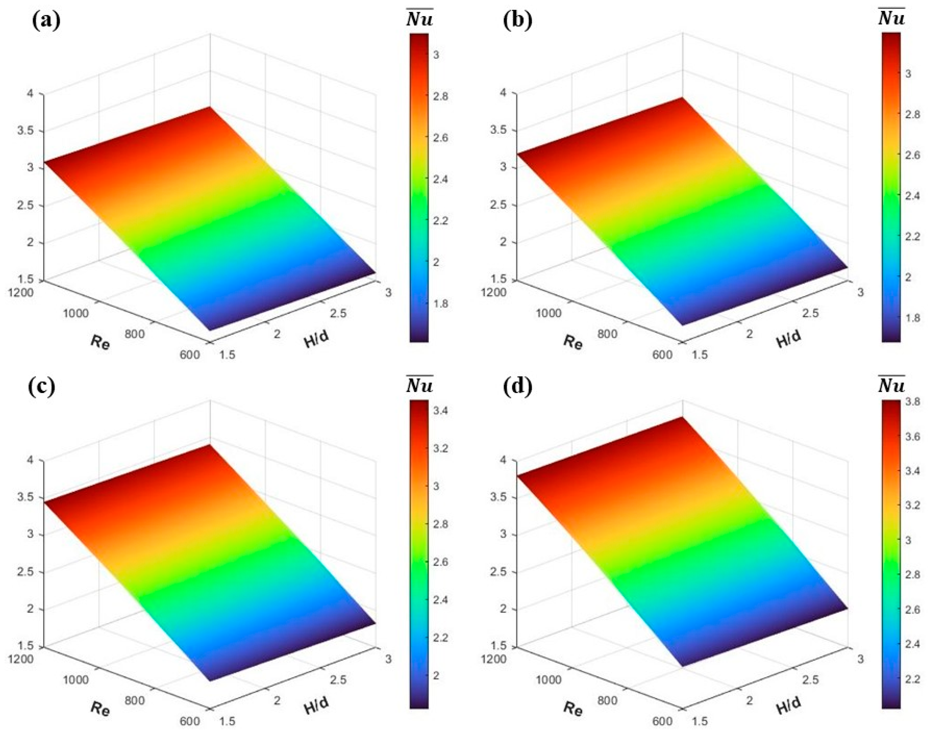
Section 5 provides optimized KM results and discusses the effect of operating parameters on heat transfer performance and the results of sensitivity analysis and optimization. Finally, Section 6 provides the conclusions of this study.

2. Experimental Methods

The PMIFJ system used in this study consists of a burner, the flow output and control system of fuel and air, and a water–cooled alumina plate, as shown in Figure 1. The burner comprises a diverging tube, three equalizing chambers, and a converging nozzle. Methane (purity 99.95%) and dry air are controlled by two mass flow controllers (MFC, DPC–47, Aalborg Instruments & Control Int., New York, NY, USA) with an accuracy of ± 0.01 SLPM. Methane and air are mixed in a mixing chamber, and the mixture is introduced into the burner. Five layers of stainless steel mesh are installed in the burner to reduce the flow fluctuations of the mixture, ensure uniform flow, and prevent flame flashback. Gaskets are utilized to prevent methane and air leaks. Finally, the mixture flows to the nozzle exit to produce a laminar premixed methane–air flame. The volume flow rate of methane and air is determined based on different equivalence ratios and Reynolds number operating conditions. The equivalence ratio ( ϕ ) and Reynolds number ( R e ) of the PMIFJ are defined as follows:
ϕ = Q C H 4 / Q a i r a c t Q C H 4 / Q a i r s t
where Q C H 4 and Q a i r are the volume flow rates of methane and air, respectively.
R e = ρ m V e d μ m
where ρ m is the density of the mixture, V e is the velocity of nozzle exit, d is the nozzle diameter, and μ m is the dynamic viscosity of the mixture.
ρ m = Y i ρ i
where Y i is the mass fraction of species i , and ρ i is the density of species i .
μ m = μ i X i M i X i M i
where μ i is the dynamic viscosity of species i , X i is the molar fraction of species i , and M i is the molar mass of species i .
In order to observe the flame shape and characteristics of PMIFJ, luminous images of the flame were taken by a 4K CMOS camera. In addition, the cone’s leading edge defines the height of the premixed cone to provide validation for numerical simulations. To verify the heat transfer performance of the simulated PMIFJ, a water–cooled alumina plate was used as a heat exchanger to measure its total heat transfer rate. Aluminum sticks fixed the heat exchanger and adjusted the distance of nozzle–to–plate ( H ). A water pump and water flow meter supply the cooling water at a constant room temperature and flow rate to the heat exchanger. Two K–type thermocouples were used to measure the temperature of the water flowing into and out of the heat exchanger. After the mixture is ignited, the inlet and outlet water temperatures are recorded through the temperature acquisition card (NI USB-9162, National Instruments, Austin, TX, USA) once the outlet water temperature reaches a steady state. According to the energy balance equation for cooling water under steady-state conditions [44], Equation (5) calculates the total heat transfer rate at different conditions.
Q ˙ T = m ˙ C P T o u t T i n
where Q ˙ T is the total heat transfer rate, m ˙ is the mass flow rate of water, C P is the specific heat of water, and T i n and T o u t are the water temperatures at the inlet and outlet of the heat exchanger, respectively.

3. Numerical Simulation

This study used ANSYS Fluent® 20.0 R1 based on the finite volume method to simulate the combustion and heat transfer characteristics of laminar PMIFJs.

3.1. The Governing Equations

Gravity effects are considered based on two–dimensional, steady–state, laminar, and incompressible flow. The general forms of mass, momentum, energy, and species conservation equations are as follows:
The mass conservation equation
· ρ V = 0
where ρ is the density, and V is the velocity vector, which is composed of the axial velocity component ( V z ) and the radial velocity component ( V r ) of the two-dimensional axisymmetric flow.
The momentum conservation equation
· ρ V V = P + ρ g + · τ =
where P is the static pressure, g is the gravity acceleration, and τ = is the stress tensor.
The energy conservation equation
· V ρ E + P = · k T + τ = · V i = 1 N e i   J i + S h
where E is the energy, k is the thermal conductivity, T represents the temperature gradient, e i is the enthalpy of species i , S h includes the heat of chemical reaction and any other defined volume heat source, and J i is the diffusion flux of species i . For laminar flow, J i is expressed as:
J i = ρ D m , i Y i D t , i T T
where D m , i and D t , i are the mass and thermal diffusion coefficient of species i in the mixture, respectively.
The species conservation equation
· ρ V Y i = · J i + R i
where R i represents the net productivity of species i in the chemical reaction.

3.2. Computational Domain, Boundary Conditions, and Mesh Setup

The two–dimensional axisymmetric computational domain was established using Ansys DesignModeler®, as shown in Figure 2. The coordinate origin is set at the center of the nozzle exit, and the axial and radial directions are represented by z and r , respectively. The nozzle’s diameter ( d ) is 13.5 mm, and its wall thickness is 0.55 mm. The heat exchanger has a diameter ( D ) of 210 mm and a thickness of 2 mm. The radial dimension of the domain is fixed at 105 mm, which is the same size as the heat exchanger. Previous studies have demonstrated that this radial distance is long enough to allow the development of radial flow and ensure an equilibrium state of the burned gas at the outlet boundary [4,45]. In order to calculate the nozzle–to–plate distance, change the axial dimension to H = 20.25~40.5 mm (i.e., H / d = 1.5~3.0). Figure 2 also shows the different boundary conditions in this domain. The axisymmetric boundary condition is imposed at the centerline of the nozzle. This study uses a converging nozzle, so the velocity distribution at the nozzle exit is a top–hat distribution, which is approximated using a sixth–power polynomial, as shown in Equation (11). An expression language is adopted to set the velocity inlet condition.
V z = V z m a x a 6 r R 6 + a 5 r R 5 + a 4 r R 4 + a 3 r R 3 + a 2 r R 2 + a 1 r R + a 0
where R is the radius of the nozzle, a 0 is the constant term, and a 1 ~ a 6 are the coefficients of each multi–order term, respectively. Furthermore, the inlet temperature is set to 300 K. The methane–air mixture at the inlet is set according to different equivalence ratio ( ϕ ) conditions to set the mass fraction of different gases. When ϕ = 1, the mass fractions of methane, oxygen, and nitrogen are:
Y C H 4 = 0.055   ;   Y O 2 = 0.22   , Y N 2 = 0.725   f o r   a i r   ( 21 %   O 2 ,   79 %   N 2 )
The pressure inlet and outlet boundaries are set to ambient air under room temperature and atmospheric pressure conditions as follows:
T = 300   K   ;   P = P a t m   ;   Y O 2 = 0.23   ;   Y N 2 = 0.77     f o r   a i r   ( 21 %   O 2 ,   79 %   N 2 )
The nozzle edge and impingement plate are regarded as wall boundaries, and conditions of no–slip and constant temperature (300 K) are set. In this study, to consider solid heat transfer for a wall region with solid and fluid regions on each side, the “two–sided wall” method is adopted to calculate the internal heat transfer between the methane–air premixed flame and the solid. It is set to the “coupled” condition to calculate heat transfer from profiles in adjacent cells and calculate heat fluxes in fluids and solid walls according to Fourier’s law. The solid material is set to aluminum, with a thermal conductivity coefficient of 202.4 W/m-K.
ANSYS Meshing® was used for meshing, and the overall computational domain was discretized using a quadrilateral structured mesh, as shown in Figure 3. For demonstration and clarity, the meshes in the figure are shown to be much sparser than the actual meshes. In the central flame and near–plate regions, high–resolution meshes are used to accurately analyze the fluid flow, mass transfer, and heat transfer behaviors in these regions. The mesh size in the central flame region (0   r   10 mm) is set to a non–uniform quadrilateral mesh with r = 50 μ m and z = 200 μ m . The mesh is refined in the region close to 5 mm from the plate by reducing the axial mesh size to 0.25 times. Outside the central flame and near–plate regions, the mesh size gradually increases to minimize the total mesh number.

3.3. Numerical Models

To obtain the most reliable simulation results for the PMIFJ, a double–precision implicit separation solver was used in Fluent, and GRI–Mech 3.0 of the detailed chemical mechanism for methane was used (53 species and 325 reactions) [46]. Additionally, each species’ thermodynamic and transport properties are imported into Fluent in Chemkin format. The specific heat capacity of each species is obtained based on a temperature–dependent piecewise polynomial approximation, and its viscosity and thermal conductivity were calculated using kinetic theory. For mixtures, the density and specific heat capacity are calculated according to the incompressible ideal gas law and the mixing law, respectively. The ideal gas mixing law calculates the mixture’s viscosity and thermal conductivity. The mass diffusion coefficient is calculated using kinetic theory. Since the flow state of the PMIFJ discussed in this study is laminar flow, the laminar finite rate turbulence–chemistry interaction is selected, which ignores the influence of turbulence fluctuation. The laminar finite rate model is acceptable for combustion with small turbulence–chemistry interactions. The volumetric reaction uses the stiff chemistry solver and multi–component diffusion. The in situ adaptive tabulation (ISAT) algorithm of the integration method proposed by Pope is adopted [47] to reduce the computational load of time integration and achieve detailed chemistry. The ISAT error tolerance is a vital setting parameter that controls the numerical errors that occur when retrieving data from the ISAT table. The ISAT error tolerance is set to 5 × 10⁻⁵ to ensure that the results of interest in this study remain unchanged. In addition, the maximum storage setting of ISAT is 500 MB.
In all cases, the coupling between pressure and velocity is accomplished using the SIMPLE algorithm. The second–order upwind scheme is used for the spatial discretization. The volumetric reaction and energy equation are canceled in the solver to solve non–reacting flow (cold flow). It takes about 1500~2000 iterations until convergence. A small region above the nozzle exit is patched with an artificially specified temperature of 2000 K to ignite the mixture. The under–relaxation factors of all species equations are set to 0.1, and the under–relaxation factor of the energy equation is set to 0.05 to avoid computational divergence. The volumetric reaction and energy equations are then activated, and the solution of the reactive flow is calculated by solving the mass, momentum, matter, and energy conservation equations. The under–relaxation factors are gradually raised to their default values once ignition occurs. For computational convergence, the residual convergence criteria for the continuity, momentum, and species equations are set to 10−6 and to 10−8 for the energy equation. In addition, the total heat transfer rate at the two–sided wall is monitored to ensure that the iteration process is complete.

3.4. Mesh Independence Testing

When using the CFD method for research, mesh independence testing is necessary first. This testing ensures that the simulation results will not change with further mesh refinement. It is common to perform at least three simulations to evaluate changes in the results of interest and to obtain the minimum number of meshes and mesh size settings that guarantee reliable results. Five meshes with different mesh numbers are used in this work to perform mesh independence testing. The entire computational domain has a total of N r × N z mesh points along the radial and axial directions. There are n r × n z mesh points in the central possible flame region ( 0 r 10  mm, 0 z 22  mm), and the mesh points corresponding to different mesh numbers are shown in Table 1. The local heat flux ( q ) distribution is used to verify mesh independence since heat transfer in the PMIFJ is the main focus. Figure 4 shows the q distribution of the stagnation point along the + r direction. The q distribution within the wall jet region remains almost consistent. There are obvious differences in the q distribution at the stagnation and the jet–turning regions, and the q distribution decreases as the mesh number increases. When the mesh number increases to 78,634 and 103,434, the heat flux distributions from the stagnation point to the peak almost overlap, indicating that the two mesh numbers have fairly good mesh independence. In other words, when the number of meshes is higher than 78,634, the effect of the meshes on the heat transfer performance is negligible. Therefore, we finally selected the mesh number 78,634 as the best mesh number for CFD simulation in this study, which not only produced the smallest numerical error but also reduced the computational cost and time.

3.5. Model Validation

Figure 5a shows the PMIFJ under the conditions of stoichiometric ratio, R e = 1000, and H / d = 2. The simulated OH radical contour and the actual flame image are on the left and right, respectively. The height of the premixed cone ( H C ) has been used as a validation index because it is a function of laminar flame speed and plays a key role in the PMIFJ’s heat transfer. The contour of the OH mass fraction can be used to identify the reacting region and has been used to determine the height of the premixed cone [48]. Therefore, the H C of PMIFJ at different Reynolds numbers are compared between the numerical simulations and the experimental results, as shown in Figure 5b. There is little difference between the simulation and experimental results. This study mainly focuses on the heat transfer behavior of the PMIFJ, so it also further verifies the total heat transfer rate of the impingement plate, as shown in Figure 6. The total heat transfer rate increases monotonically with R e raises. It can be found that the experimentally measured total heat transfer rate is low, which may be attributed to the local heat loss at the measurement location of the actual heat exchanger. Another reason is that condensed water droplets adhered to the surface of the heat exchanger during the experiment, and these water droplets absorb the heat generated by the PMIFJ. In summary, the flame behavior and heat transfer trend of the PMIFJ can be predicted using the CFD method and the GRI–Mech 3.0 mechanism.

4. Surrogate–Based Optimization (SBO)

The process of surrogate–based optimization is shown in Figure 7. First, the orthogonal array (OA) method is adopted to generate initial sample points. The simulation results obtained by the CFD method are used to construct the initial KM. The root mean square error (RMSE) is used as the infilled criterion, and the genetic algorithm (GA) is adopted to search for the maximum RMSE to determine new infilled points. The infilled points are used to reconstruct the KM. Then, the decreasing ratio of RMSE is used as the termination criterion to avoid wasting computational cost and time. The following sub–sections will introduce more detailed information.

4.1. Orthogonal Array

The initial sample points are generated by the OA method to construct the initial KM. Valuable information can be obtained by analyzing a small number of factor (parameter) combinations, and the expression of the orthogonal array is L a b c . Among them, L represents the Latin square; a is the number of test runs, and b and c are the level and number of factors, respectively. This study mainly explores three parameters, namely ϕ , R e , and the normalized nozzle–to–plate distance ( H / d ), and each parameter has four levels. Hence, L 16 4 3 orthogonal array is used, as shown in Table 2. In addition, the objective function needs to be defined first before the initial KM can be constructed. Nusselt number ( N u ) is a dimensionless parameter commonly used in heat transfer analysis. It is defined as the ratio of convective heat transfer to conductive heat transfer at the solid–fluid interface [49], as shown in Equation (12):
N u = h d k = q d k ( T w T a d )
where h is the local convective heat transfer coefficient, k is the thermal conductivity of the fluid, T w is the wall temperature, and T a d is the adiabatic flame temperature. For a simplified problem of axisymmetric, the average Nusselt number ( N u ¯ ) of the impingement plate is calculated as follows:
N u ¯ = 1 A A N u   d A = 2 R 2 0 R N u r r   d r
N u ¯ is mainly used to evaluate a heating or cooling system’s global convection heat transfer performance [50,51] to analyze and optimize the system further. Therefore, it is very appropriate to use N u ¯ as the objective function of this study.

4.2. Kriging Model

Recently, the KM has extensively applied approximate complex computational models. The KM is a half parametric interpolation method, which contains the global model and local deviation [52], shown as follows:
Y x = β + Z x
where y x is the unknown objective function of x , and β is the constant mean since the ordinary KM is used in this study. Z x is the local deviation, which is the realization of a stationary Gaussian process with mean zero.
E Z x = 0
Z x can be determined with non–zero covariance matrix of
C O V Z x i ,   Z x j   = σ 2 F F x i , x j ,
In Equation (16), the superscript i = j = 1 , ,   n s . Here, n s represents the number of sample points. σ 2 is the process variance of the spatial correlation function scalar, and F is the n s × n s correlation matrix. F x i , x j is the spatial correlation function between any two sample points x i and x j . The correlation function is the Gaussian correlation function, which can be defined as Equation (17):
F   x i , x j = e x p k = 1 n θ k x k i x k j 2
where n is the number of variables, and θ k is the unknown correlation parameter used to fit the model, which can be obtained by the maximum likelihood estimation (MLE) theory, as shown in Equation (18):
θ k > 0 m a x n s   l n σ ^ 2 + l n F 2
The predicted value of the KM for the unknown x point is shown as follows:
y ^ x = β ^ + f x T F 1 y 1 β ^
where f x T is the correlation vector between known sample points and unknown x, as shown in Equation (20). y is the vector of n s   × 1, including the sample values of the response, and 1 is the unit vector of n s   × 1.
f x = F x , x 1 , F x , x 2 , ,   F x , x n s T
β ^ and σ ^ 2 can be calculated as follows:
β ^ = 1 T F 1 y 1 T F 1 1
σ ^ 2 = y 1 β ^ T F 1 y 1 β ^ n s
The mean square error (MSE) of the KM prediction at x is calculated by Equation (23), which represents the uncertainty of the prediction value.
s ^ 2 = σ ^ 2 1 f T F 1 f + 1 1 T F 1 f 1 T F 1 1

4.3. Infilling Criteria

In order to improve the accuracy of KM prediction, it is necessary to sequentially fill in new sample points. After adding the new point, the KM model would be refitted. The infilled criteria for selecting new sample points include the maximum RMSE, the maximum expected improvement, and the minimum predicted objective function [48], which can be selected according to the purpose of use. The infilled criterion in this study is to use the maximum RMSE to ensure that a high global accuracy KM can be obtained. The decreasing ratio of RMSE is used as the termination criterion for the infilling process [49]. Several randomly generated or specific checkpoints are then used, and the accuracy of KM is quantified and evaluated through the relative error ( e r ). e r has been used as the evaluation index of the surrogate model [53] and is calculated by Equation (24).
e r = S V P V S V × 100 %
where S V and P V are the simulated value of CFD and the predicted value of KM at the checking point, respectively.

4.4. Genetic Algorithm

GA is a survival strategy of the fittest based on the theory of biological evolution and is often utilized in the optimization of practical engineering problems [54,55]. Its optimization process mainly includes selection, crossover, and mutation operations [56]. Three maximization problems are included in this study’s SBO process. The first is constructing a parameter combination in the KM to determine the maximum likelihood function (MLE) value to obtain the best model fit. The second is to determine new infilled points according to the criterion of maximizing RMSE and add them to KM to improve the global prediction accuracy. The third is determining optimal heat transfer performance on the final KM. In GA, chromosomes represent parameters in the optimization problem, and fitness is the corresponding objective function. The GA code is compiled based on the book [57] in this paper. The basic GA steps are as follows:
(1)
Generate the initial population: Randomly generate chromosomes (individuals), with each chromosome using binary coding to represent different parameters of the problem, and evaluate the fitness of each chromosome.
(2)
Selection: Mainly performed through tournament selection, selecting chromosomes with higher fitness for subsequent operations.
(3)
Crossover: Select two chromosomes to perform a two–point crossover operation to generate a new chromosome.
(4)
Mutation: Randomly transform some chromosome genes to introduce genetic diversity.
(5)
Selection and update: Update the population according to fitness, eliminate chromosomes with low fitness, and retain chromosomes with high fitness into the next generation.
(6)
Termination condition: Repeat the above process until the set number of generations is reached and the optimal generation is obtained.
We execute these three optimization problems using the GA process mentioned above. The entire process gradually approaches the optimal solution through multiple iterations without calculating the differential of the objective function. It is suitable for complex objective functions or challenging to calculate the differential directly. The GA code is executed through MATLAB® to search for the optimal solution. The GA’s setting parameters are as follows: The population size and number of generations are set to 100 and 200, respectively. The crossover and mutation probabilities are set to 0.6 and 0.1, respectively.

5. Results and Discussion

5.1. Optimization of the KM

Table 3 lists the conditions and N u ¯ of all sample points in the operating parameter space, including sixteen initial points, four infilled points, and six checking points. The distribution of these sample points in the parameter space is shown in Figure 8. In constructing the initial KM, the RMSE of the unknown sample points is calculated through Equation (23), and four infilled points are determined based on the maximizing RMSE criterion. The maximum RMSE value can drop from 0.00805 to 0.00303 by adding these infilled points. The decreasing ratio reaches 62.5%, thus stopping the infilling procedure. Equation (24) is used to calculate the relative errors of six checking points, as shown in Table 4. The results show that the relative error between the predicted value of KM and the simulated value of CFD is within 1%, which is enough to prove that the predictive ability of KM for N u ¯ is reliable. This means the objective function of predicting unknown points using the KM method can replace the empirical correlation proposed in the previous literature. In addition, compared with the 34 = 81 sample points required by the full factorial design, this studied method only used 20 sample points, representing a 75.3% reduction in the simulated times of CFD.

5.2. Effects of the Parameters on N u ¯

5.2.1. The Effect of ϕ on N u ¯

At fixed equivalence ratios of 0.9, 1.0, 1.1, and 1.2, respectively, the response surface plots of the average Nusselt number within the operating parameter range ( R e = 600~1200, H / d = 1.5~3.0) are shown in Figure 9. N u ¯ rises as the equivalence ratio increases because the flame temperature is higher at stoichiometric and slightly rich conditions than at lean conditions [19]. Additionally, although the maximum flame temperature at ϕ = 1.2 is lower than that at ϕ = 1.0 and 1.1, the global heat transfer performance is actually better due to the longer flame length and more released heat. Section 5.4 discusses this in detail.

5.2.2. The Effect of R e on N u ¯

Figure 10 shows the response surface plots of different Reynolds numbers to the average Nusselt number within the range of operating parameters ( ϕ = 0.9~1.2, H / d = 1.5~3.0). N u ¯ rises with the increase in R e , meaning that the global heat transfer imposed on the impingement plate is enhanced because the PMIFJ with high R e has more convective heat transfer [19,58]. The large concentration of reactive species at the flame’s inner reaction region enhances convection heat transfer by their diffusion and exothermic recombination on the impingement surface [22]. The influence of the equivalence ratio on heat transfer performance becomes more significant as the Reynolds number increases.

5.2.3. The Effect of H / d on N u ¯

Figure 11 provides the response surface plots of different H/d for the average Nusselt number within the operating parameter range ( ϕ = 0.9~1.2, R e = 600~1200). It can be found that N u ¯ slightly decreases when H / d increases because more cold ambient air is involved in the post–flame and wall jet regions of the PMIFJ. This causes the temperature to drop, thus reducing the global heat transfer performance [59]. In addition, it can be inferred from the response surface plots that R e affects the global heat transfer performance more obviously than ϕ .

5.3. Sensitivity Analysis

Sensitivity analysis is according to Equation (17) to calculate the θ value of each parameter to evaluate the influence of ϕ , R e , and H / d on N u ¯ , as shown in Table 5. The larger the value of θ , the more significant the influence. The results show that the θ value corresponding to R e is higher than the θ value corresponding to ϕ and H / d . This means that R e affects the global heat transfer performance most obviously, and it also means that the inlet velocity of the PMIFJ is an important parameter, followed by ϕ , and H / d has the slightest effect.

5.4. The Effect of R e and ϕ on the Flow, Temperature, and Heat Transfer Characteristics of the PMIFJ

By sensitivity analysis, it is known that R e and ϕ are the crucial parameters affecting the heat transfer performance of the PMIFJ. The flow field, temperature field, and radial N u distribution are presented to further explore the reasons for their influence. First, the effect of R e on the PMIFJ is discussed. At fixed ϕ = 1.2 and H / d = 1.5, the contours of the velocity and temperature fields at different Reynolds numbers are shown in Figure 12. The premixed cone’s height rises with R e because of the increase in inlet axial velocity. It is also observed that as R e increases, the velocity behind the reaction region also rises, causing the PMIMJ to spread more and the high–temperature region to become more extensive. Figure 13 provides the radial N u distribution for different Reynolds numbers. Compared with the N u distribution of R e = 800, the N u distribution of R e = 600 in the stagnation region is much lower because the lower Reynolds number equals less fuel usage. Another reason is that Figure 12a shows the existence of a low–velocity region, which causes the stagnation region to expand and reduce its temperature. This is consistent with the results measured by Tolstoguzov and Chikishev using non–invasive laser diagnostic technology [60]. It may be related to the velocity distribution at the burner exit. The velocity distribution of the top hat is produced by the nozzle burner used in this study and in Ref. [60]. It is different from the parabolic velocity distribution using a tube burner [4,8,26,45]. The stagnation point’s Nusselt number ( N u 0 ) of R e = 1000 is reduced to 9 due to the low–temperature premixed cone (unburned mixture) slightly hitting the impingement plate. In addition, the peak Nu is far away from the stagnation point because of the shift of the peak axial velocity [26]. When the R e value increases to 1200, more low–temperature premixed cones are intercepted by the impingement plate, which means there is more unburned mixture in the stagnation region, further suppressing the heat flux at the stagnation point. Therefore, N u 0 has zero value in a small region. The unburned mixture burns a short distance from the stagnation point to obtain chemical energy, resulting in maximum heat flux in this region. Therefore, the peak N u of R e = 1200 is greater than the peak N u of R e = 1000. In the wall jet region, the radial N u distribution significantly rises as R e increases. As mentioned, the PMIFJ with high R e has a more diffuse and extensive high–temperature region, promoting more convective heat transfer.
Figure 14 provides contours of the velocity and temperature fields for different equivalence ratios at fixed R e = 1200 and H / d = 2.0. As ϕ increases from 0.9 to 1.2, the height of the premixed cone first decreases and then increases, which is inversely proportional to the laminar flame speed of the premixed methane flame [59]. It can also be found that the velocity behind the reaction region is directly proportional to the laminar flame speed. When the equivalence ratio gradually increases, its velocity increases and then decreases. The flame temperature of ϕ = 0.9 is lower than the other three due to less fuel participating in the reaction. Figure 15 shows the radial N u distribution of different equivalence ratios. The results show that for fixed H / d , when the premixed cone does not touch the impingement plate, the closer the flame tip is to the plate,  N u 0  is higher, which is consistent with the results observed by Chander and Ray [19]. In the wall jet region, the radial N u distribution rises with increasing ϕ since more fuel is burned (releasing more heat), which is the major exothermic reaction from the oxidation of CO to CO2 in the post–flame region of the premixed cone [4]; that is, OH + CO → CO2 + H. The distribution of OH changes more widely with ϕ = 0.9 increases to 1.2, as shown in Figure 16. In addition, it is also observed that the OH concentration in the reaction zone is related to the N u value in the stagnation zone. PMIFJs with ϕ = 0.9 and 1.2 have similar premixing cone heights, and the radial N u distribution also has the same trend. However, the OH concentration of ϕ = 0.9 is higher than that of ϕ = 1.2, causing the N u value of ϕ = 0.9 in the stagnation region to be greater than ϕ = 1.2. The N u distribution at ϕ = 0.9 in the wall jet region is significantly decayed, attributed to excess air in the unburned mixture and less heat released by the flame [25,59].

5.5. The Optimized Solution for N u ¯

Using the optimized KM and the GA method to search within the operating parameter range, the parameter combination with the largest N u ¯ is ϕ = 1.2, R e = 1200, and H / d = 1.5. Consistent with previous literature results, the maximum heat transfer performance occurs at slightly rich fuel conditions, and the premixing cone slightly hits the impingement plate [59,61], as shown in Figure 12d. The previous response surface plots for N u ¯ with different parameters confirm that the GA search is correct.

6. Conclusions

This study used the CFD method and the GRI–Mech 3.0 mechanism to numerically investigate the combustion and heat transfer characteristics of PMIFJs, which were verified through experimental results. The orthogonal array was used to generate initial sample points for ϕ , R e , and H / d combinations. The KM and GA were used to create a model to predict unknown points and determine the optimized solution to the problem. Maximizing RMSE was used as an infilled criterion to improve the prediction accuracy of the KM. In addition, the effects of three operating parameters on PMIFJs are further analyzed. The following conclusions can be drawn from the results:
  • The KM with good prediction ability is obtained through twenty sample points (sixteen initial points and four infilled points). Compared with six checking points more sensitive to N u ¯ , the maximum relative errors are all within 1%. Moreover, this method reduces the simulated times of CFD by 75.3%.
  • From the response surface plots, it is known that N u ¯ of the PMIFJ shows an upward trend with the increase in ϕ , the increase in R e , and the decrease in H / d . Moreover, the effect of ϕ is more significant with increasing R e .
  • The sensitivity analysis points out that the ranking of operating parameters affecting global heat transfer performance is R e > ϕ H / d , which means that the inlet velocity is the main key parameter, followed by the fuel–to–air ratio.
  • It is found that the height of the premixed cone and the scope of the high temperature post–flame region will significantly affect the behavior of local heat transfer.
  • The parameter combination to determine the maximum global heat transfer performance through GA is ϕ = 1.2, R e = 1200, and H / d = 1.5, which means that the PMIFJ is at slightly rich–fuel and high–velocity conditions and its premixed cone slightly hits the impingement plate.
The main contribution of this paper is to provide an efficient prediction and optimization method framework for the heat transfer performance in the field of impinging flame jets. Although the proposed method applies to the heat transfer performance of premixed impinging flame jets, similar strategies can be effectively applied to combustion systems such as combustors, boilers, and turbine engines to systematically analyze the effects of each design variable (operating parameter) on thermal efficiency. In addition, this method is not limited to heat transfer performance but can also be used to predict and optimize pollutant emissions, such as NOx, CO, and particulate matter (PM). Currently, only a single objective function is modeled and optimized. The multiple objectives optimization of combustion systems is becoming increasingly crucial as combustion technology moves toward becoming more efficient and cleaner. However, multiple objectives are usually relative and contradictory. For example, enhancing the efficiency of the combustion system will raise NOx emissions due to the increase in thermal NO. Therefore, the multiple-objective optimization can be transformed into a single-objective optimization problem through the weighting function, or the multi-objective non-dominated sorting genetic algorithm (NSGA-II) can be introduced to determine the optimal solution that maximizes the balance of each objective.

Author Contributions

Conceptualization, X.-X.C.; Methodology, R.-B.C. and C.-Y.W.; Software, X.-X.C.; Validation, X.-X.C., R.-B.C. and C.-Y.W.; Formal Analysis, X.-X.C.; Investigation, X.-X.C.; Resources, R.-B.C. and C.-Y.W.; Data Curation, X.-X.C.; Writing—Original Draft Preparation, X.-X.C.; Writing—Review and Editing, R.-B.C. and C.-Y.W.; Visualization, X.-X.C.; Supervision, C.-Y.W.; Project Administration, R.-B.C. and C.-Y.W.; Funding Acquisition, C.-Y.W. All authors have read and agreed to the published version of the manuscript.

Funding

National Science and Technology Council, Taiwan, under Grant No. 111-2118-M-006-002-MY2 (R.-B.C.) and 112-2221-E-006-107 (C.-Y.W.).

Institutional Review Board Statement

Not applicable.

Informed Consent Statement

Not applicable.

Data Availability Statement

The data presented in this study are available on request from the corresponding author.

Acknowledgments

We would like to thank the Department of Aeronautics and Astronautics, NCKU, for providing part of the computing resources.

Conflicts of Interest

The authors declare no conflicts of interest.

Nomenclatures

Symbol
A Area
a Number of test runs
a 0 Coefficient of constant term
a 1 ,   a 2 , a 3 , a 4 , a 5 , a 6 Coefficients of each multi-order term
b Factor level
C P Specific heat of water
c Factor number
D Heat exchanger diameter
D m Mass diffusion coefficient
D t Thermal diffusion coefficient
d Nozzle diameter
E Expectation
E Energy
e Enthalpy
e r Relative error
F Correlation matrix
F Spatial correlation function
f Correlation vector
g Gravity acceleration
H Distance of nozzle–to–plate
H C Height of the premixed cone
h Local convective heat transfer coefficient
k Thermal conductivity
J Diffusion flux
L Latin square
M Molar mass
m ˙ Mass flow rate
N Nth species
N r Total mesh points along the radial direction
N z Total mesh points along the axial direction
N u Local Nusselt number
N u ¯ Average Nusselt number
n Number of variables
n s Number of sample points
n r Mesh points in the central flame region along the radial direction
n z Mesh points in the central flame region along the axial direction
P Static pressure
P V Simulated value of CFD
Q Volume flow rate
Q ˙ T Total heat transfer rate
q Local heat flux
R Nozzle radius
W Net productivity
R e Reynolds number
r Radial direction
r Radial mesh size
S h Heat source
S V Predicted value of the KM
s ^ 2 Mean square error
T Temperature
V Velocity vector
V e Velocity of nozzle exit
V r Radial velocity component
V z Axial velocity component
W Net productivity
X Molar fraction
x Variable or parameter
Y Mass fraction
y Unknown objective function of x
Z Local deviation
z Axial direction
z Axial mesh size
1 Unit vector of n s   × 1
Greek Symbols
β Constant mean
θ k Unknown correlation parameter
μ Dynamic viscosity
ρ Density
σ 2 Process variance of the spatial correlation function scalar
τ = Stress tensor
ϕ Equivalence ratio
Subscripts
a c t Actual
a d Adiabatic flame
a t m Atmospheric pressure
i Species i
i n lnlet
m Mixture
m a x Maximum
o u t Outlet
s t Stoichiometric
w Wall

References

  1. Morad, M.; Momeni, A.; Fordoei, E.E.; Ashjaee, M. Experimental and numerical study on heat transfer characteristics for methane/air flame impinging on a flat surface. Int. J. Therm. Sci. 2016, 110, 229–240. [Google Scholar] [CrossRef]
  2. Hindasageri, V.; Vedula, R.P.; Prabhu, S.V. A novel method of estimation of adiabatic wall temperature for impinging premixed flame jets. Int. J. Heat Mass Transf. 2014, 77, 185–193. [Google Scholar] [CrossRef]
  3. Kadam, A.R.; Parida, R.K.; Hindasageri, V.; Kumar, G. Heat transfer distribution of premixed methane-air laminar flame jets impinging on ribbed surfaces. Appl. Therm. Eng. 2019, 163, 114352. [Google Scholar] [CrossRef]
  4. Zhen, H.; Zhang, L.; Wei, Z.; Chen, Z.; Huang, Z. A numerical study of the heat transfer of an impinging round-jet methane Bunsen flame. Fuel 2019, 251, 730–738. [Google Scholar] [CrossRef]
  5. Wu, C.-Y.; Chen, K.-H.; Yang, S.Y. Experimental study of porous metal burners for domestic stove applications. Energy Convers. Manag. 2014, 77, 380–388. [Google Scholar] [CrossRef]
  6. Hindasageri, V.; Kuntikana, P.; Vedula, R.P.; Prabhu, S.V. An experimental and numerical investigation of heat transfer distribution of perforated plate burner flames impinging on a flat plate. Int. J. Therm. Sci. 2015, 94, 156–169. [Google Scholar] [CrossRef]
  7. Hua, J.; Pan, J.; Li, F.; Fan, B.; Li, Z.; Ojo, A.O. Heat transfer characteristics of premixed methane-air flame jet impinging on a hemispherical surface. Fuel 2023, 343, 127698. [Google Scholar] [CrossRef]
  8. Zhen, H.; Chen, K.; Chen, Z.; Wei, Z.; Fu, L. Heat transfer analysis of impinging flames using field synergy principle. Case Stud. Therm. Eng. 2023, 43, 102807. [Google Scholar] [CrossRef]
  9. Chander, S.; Ray, A. Flame impingement heat transfer: A review. Energy Convers. Manag. 2005, 46, 2803–2837. [Google Scholar] [CrossRef]
  10. Remie, M.; Särner, G.; Cremers, M.; Omrane, A.; Schreel, K.; Aldén, L.; De Goey, L. Heat-transfer distribution for an impinging laminar flame jet to a flat plate. Int. J. Heat Mass Transf. 2008, 51, 3144–3152. [Google Scholar] [CrossRef]
  11. Hindasageri, V.; Vedula, R.P.; Prabhu, S.V. Heat transfer distribution for impinging methane–air premixed flame jets. Appl. Therm. Eng. 2014, 73, 461–473. [Google Scholar] [CrossRef]
  12. Parida, R.K.; Kadam, A.R.; Vasudeva, M.; Hindasageri, V. Heat transfer characterisation of impinging flame jet over a wedge. Appl. Therm. Eng. 2021, 196, 117277. [Google Scholar] [CrossRef]
  13. Baukal, C.E.; Gebhart, B. Surface condition effects on flame impingement heat transfer. Exp. Therm. Fluid Sci. 1997, 15, 323–335. [Google Scholar] [CrossRef]
  14. Cremers, M.; Remie, M.; Schreel, K.; de Goey, L. Thermochemical heat release of laminar stagnation flames of fuel and oxygen. Int. J. Heat Mass Transf. 2010, 53, 952–961. [Google Scholar] [CrossRef]
  15. Zhang, Y.; BRAY, K.C. Characterization of impinging jet flames. Combust. Flame 1998, 116, 671–674. [Google Scholar] [CrossRef]
  16. Chao, Y.-C.; Wu, C.-Y. A study of the interaction between a jet flame and a lateral wall. Combust. Sci. Technol. 2000, 158, 93–113. [Google Scholar] [CrossRef]
  17. Chen, W.-L.; Currao, G.; Wu, C.-Y.; Evan, B.; Mao, C.-Y.; Tsai, S.-W.; Yu, C.-Y. A Study on an Unpressurized Medium-Temperature-Differential Stirling Engine Integrated with a New Spiral-Patterned Flat-Flame Burner and a New Spiral-Finned Hot-End Plate. Int. J. Energy Res. 2023, 2023, 8827094. [Google Scholar] [CrossRef]
  18. Wu, C.-Y.; Currao, G.M.; Chen, W.-L.; Chang, C.-Y.; Hu, B.-Y.; Wang, T.-H.; Chen, Y.-C. The application of an innovative integrated Swiss-roll-combustor/Stirling-hot-end component on an unpressurized Stirling engine. Energy Convers. Manag. 2021, 249, 114831. [Google Scholar] [CrossRef]
  19. Chander, S.; Ray, A. Influence of burner geometry on heat transfer characteristics of methane/air flame impinging on flat surface. Exp. Heat Transf. 2006, 19, 15–38. [Google Scholar] [CrossRef]
  20. Milson, A.; Chigier, N. Studies of methane and methane-air flames impinging on a cold plate. Combust. Flame 1973, 21, 295–305. [Google Scholar] [CrossRef]
  21. Hargrave, G.; Fairweather, M.; Kilham, J. Forced convective heat transfer from premixed flames—Part 1: Flame structure. Int. J. Heat Fluid Flow. 1987, 8, 55–63. [Google Scholar] [CrossRef]
  22. Hargrave, G.; Fairweather, M.; Kilham, J. Forced convective heat transfer from premixed flames—Part 2: Impingement heat transfer. Int. J. Heat Fluid Flow. 1987, 8, 132–138. [Google Scholar] [CrossRef]
  23. Kwok, L. Heat transfer characteristics of slot and round premixed impinging flame jets. Exp. Heat Transf. 2003, 16, 111–137. [Google Scholar] [CrossRef]
  24. Kuntikana, P.; Prabhu, S. Air jet impingement technique for thermal characterisation of premixed methane–air impinging flame jets. Appl. Therm. Eng. 2016, 99, 905–918. [Google Scholar] [CrossRef]
  25. Dong, L.L.; Cheung, C.S.; Leung, C.W. Heat transfer characteristics of an impinging butane/air flame jet of low Reynolds number. Exp. Heat Transf. 2001, 14, 265–282. [Google Scholar]
  26. Chander, S.; Ray, A. Experimental and numerical study on the occurrence of off-stagnation peak in heat flux for laminar methane/air flame impinging on a flat surface. Int. J. Heat Mass Transf. 2011, 54, 1179–1186. [Google Scholar] [CrossRef]
  27. Hindasageri, V.; Kuntikana, P.; Tajik, A.R.; Vedula, R.P.; Prabhu, S.V. Axis switching in impinging premixed methane-air flame jets. Appl. Therm. Eng. 2016, 107, 144–153. [Google Scholar] [CrossRef]
  28. Singh, P.; Chander, S. Study of flow field and heat transfer characteristics for an interacting pair of counter-rotating dual-swirling impinging flames. Int. J. Therm. Sci. 2019, 144, 191–211. [Google Scholar] [CrossRef]
  29. Singh, P.; Velamati, R.K.; Prathap, C.; Mohammad, A.; Chander, S. Study of flow patterns and impingement heat transfer for an annular array of eight co-rotating dual-swirling flames. Int. J. Heat Mass Transf. 2019, 144, 118657. [Google Scholar] [CrossRef]
  30. Laguillo, S.; Ochoa, J.S.; Tizne, E.; Pina, A.; Ballester, J.; Ortiz, A. CO emissions and temperature analysis from an experimental and numerical study of partially premixed methane flames impinging onto a cooking pot. J. Nat. Gas Sci. Eng. 2021, 88, 103771. [Google Scholar] [CrossRef]
  31. Shakerian, M.; Karrabi, M.; Gheibi, M.; Fathollahi-Fard, A.M.; Hajiaghaei-Keshteli, M. Evaluating the Performance of a Solar Distillation Technology in the Desalination of Brackish Waters. Processes 2022, 10, 1626. [Google Scholar] [CrossRef]
  32. Wang, J.; Hu, K.; Tang, K.; Xing, Y.; Xiao, Y.; Liu, Y.; Yan, Y.; Yang, D. Numerical simulation on thermoelectric cooling of core power devices in air conditioning. Appl. Sci. 2023, 13, 7274. [Google Scholar] [CrossRef]
  33. Kim, J.-S.; Lee, W.-J.; Pham, V.C.; Choi, J.-H. A Numerical Study on Fuel Injection Optimization for a ME-GI Dual-Fuel Marine Engine Based on CFD Analysis. Appl. Sci. 2022, 12, 3614. [Google Scholar] [CrossRef]
  34. Wu, C.-Y. Numerical modeling of hydrogen catalytic reactions over a circular bluff body. Int. J. Hydrogen Energy 2022, 47, 37204–37217. [Google Scholar] [CrossRef]
  35. Li, H.; Qi, T.; Zhang, Y. Effect of furnace structure on burden distribution and gas flow in sinter vertical cooling furnace. Appl. Sci. 2023, 13, 11268. [Google Scholar] [CrossRef]
  36. Zhao, Z.; Xi, L.; Gao, J.; Xu, L.; Li, Y. Numerical Study on Cooling Performance of a Steam-Cooled Blade Based on Response Surface Method. Appl. Sci. 2023, 13, 6625. [Google Scholar] [CrossRef]
  37. Li, S.; Deng, Z.; Liu, J.; Liu, D. Multi-objective optimization of plate-fin heat exchangers via non-dominated sequencing genetic algorithm (NSGA-II). Appl. Sci. 2022, 12, 11792. [Google Scholar] [CrossRef]
  38. Chen, R.-B.; Wang, Y.; Wu, C.J. Finding optimal points for expensive functions using adaptive RBF-based surrogate model via uncertainty quantification. J. Glob. Optim. 2020, 77, 919–948. [Google Scholar] [CrossRef]
  39. Wu, C.-Y.; Wang, B.-W.; Wu, T.-H.; Chang, S.-P. Using Kriging surrogate model to analyze hydrogen generation with dimethyl ether in partial oxidation catalytic fluidized bed reactor. Int. J. Hydrogen Energy 2024, 54, 467–482. [Google Scholar] [CrossRef]
  40. Namura, N.; Shimoyama, K.; Obayashi, S. Kriging surrogate model with coordinate transformation based on likelihood and gradient. J. Glob. Optim. 2017, 68, 827–849. [Google Scholar] [CrossRef]
  41. Wang, J.; Wang, C.; Zhao, J. Frequency response function-based model updating using Kriging model. Mech. Syst. Signal Process. 2017, 87, 218–228. [Google Scholar] [CrossRef]
  42. Du, D.; He, E.; Li, F.; Huang, D. Using the hierarchical Kriging model to optimize the structural dynamics of rocket engines. Aerosp. Sci. Technol. 2020, 107, 106248. [Google Scholar] [CrossRef]
  43. Meckesheimer, M.; Barton, R.R.; Simpson, T.W.; Booker, A.J. Computationally inexpensive metamodel assessment strategies. In Proceedings of the International Design Engineering Technical Conferences and Computers and Information in Engineering Conference, Pittsburgh, PA, USA, 9–12 September 2001. [Google Scholar]
  44. E442-05; Standard Test Method for Measuring Heat Flux Using a Water-Cooled Calorimeter. (Reapproved 2011). ASTM International: West Conshohocken, PA, USA, 2011; pp. 1–5.
  45. Wei, Z.; Zhen, H.; Leung, C.W.; Cheung, C.S.; Huang, Z. Experimental and numerical study on the emission characteristics of laminar premixed biogas-hydrogen impinging flame. Fuel 2017, 195, 1–11. [Google Scholar] [CrossRef]
  46. Smith, G.P.; Golden, D.M.; Frenklach, M.; Moriarty, N.W.; Eiteneer, B.; Goldenberg, M.; Bowman, C.T.; Hanson, R.K.; Song, S.; Gardiner, W.C., Jr.; et al. GRI-Mech 3.0. Available online: http://www.me.berkeley.edu/gri_mech/ (accessed on 8 March 2023).
  47. Pope, S.B. Computationally efficient implementation of combustion chemistry using in situ adaptive tabulation. Combust. Theor. Model. 1997, 1, 41–63. [Google Scholar] [CrossRef]
  48. Mikofski, M.A.; Williams, T.C.; Shaddix, C.R.; Blevins, L.G. Flame height measurement of laminar inverse diffusion flames. Combust. Flame 2006, 146, 63–72. [Google Scholar] [CrossRef]
  49. Viskanta, R. Heat transfer to impinging isothermal gas and flame jets. Exp. Therm. Fluid Sci. 1993, 6, 111–134. [Google Scholar] [CrossRef]
  50. Costa, S.C.; Malico, I. Numerical investigation of the heat transfer characteristics of propane/air flames impinging on a cylindrical surface. Appl. Therm. Eng. 2022, 206, 118109. [Google Scholar] [CrossRef]
  51. Zhang, L.; Cao, G.; Feng, K.; Jia, Y.; Zhang, Z. Improvement of multi-hole airflow impingement on flow and heat transfer characteristics inside a turbine vane cavity. Appl. Sci. 2021, 11, 9924. [Google Scholar] [CrossRef]
  52. Lee, J.; Lee, H.; Park, H.; Cho, G.; Kim, D.; Cho, J. Design optimization of a vane type pre-swirl nozzle. Eng. Appl. Comput. Fluid. Mech. 2021, 15, 164–179. [Google Scholar] [CrossRef]
  53. Wang, G.; Huang, L.; Wang, L.; Zhao, F.; Li, Y.; Wan, R. A metamodeling with CFD method for hydrodynamic optimisations of deflectors on a multi-wing trawl door. Ocean Eng. 2021, 232, 109045. [Google Scholar] [CrossRef]
  54. Zhang, K.; Wei, W.; Sun, Y.; Wu, Q.; Tang, M.; Lu, M. Design and Optimization of the Inlet Header Structure in Microchannel Heat Exchanger Based on Flow Distribution Uniformity. Appl. Sci. 2022, 12, 6604. [Google Scholar] [CrossRef]
  55. Kwon, H.; Park, S.; Choi, J.; Han, J. A Study on the Optimization of the Louver Fin Heat Exchanger for Fuel Cell Electric Vehicle Using Genetic Algorithm. Appl. Sci. 2023, 13, 2539. [Google Scholar] [CrossRef]
  56. Holland, J.H. Genetic algorithms. Sci. Am. 1992, 267, 66–73. [Google Scholar] [CrossRef]
  57. Goldberg, D.E. Genetic Algorithms in Search, Optimization, and Machine Learning; Addison-Wesley: Boston, MA, USA, 1989. [Google Scholar]
  58. Zhao, Z.; Wong, T.; Leung, C.W. Impinging premixed butane/air circular laminar flame jet––influence of impingement plate on heat transfer characteristics. Int. J. Heat Mass Transf. 2004, 47, 5021–5031. [Google Scholar] [CrossRef]
  59. Wei, Z.; Zhen, H.; Leung, C.W.; Cheung, C.S.; Huang, Z. Heat transfer characteristics and the optimized heating distance of laminar premixed biogas-hydrogen Bunsen flame impinging on a flat surface. Int. J. Hydrogen Energy 2015, 40, 15723–15731. [Google Scholar] [CrossRef]
  60. Tolstoguzov, R.; Chikishev, L. Temperature field measurements between a Bunsen flame and flat a cold plate by using PLIF. J. Phys. Conf. Ser. 2022, 2233, 012014. [Google Scholar]
  61. Hou, S.-S.; Ko, Y.-C. Effects of heating height on flame appearance, temperature field and efficiency of an impinging laminar jet flame used in domestic gas stoves. Energy Convers. Manag. 2004, 45, 1583–1595. [Google Scholar] [CrossRef]
Figure 1. Experimental setup.
Applsci 14 03731 g001
Figure 2. Schematic diagram of computational domain and boundary conditions.
Applsci 14 03731 g002
Figure 3. Meshing process using non–uniform quadrilateral meshes.
Applsci 14 03731 g003
Figure 4. Local heat flux distribution on the impingement plate with different mesh numbers at the condition of ϕ = 1, R e = 1000, H / d = 2.
Applsci 14 03731 g004
Figure 5. Comparison between numerical and experimental results: (a) OH radical distribution and flame image at R e = 1000; (b) The height of premixed cone at different R e .
Applsci 14 03731 g005
Figure 6. Variation of total heat transfer ( Q ˙ T ) for different R e , with fixed ϕ = 1 and H / d = 2.
Applsci 14 03731 g006
Figure 7. The process of surrogate–based optimization.
Applsci 14 03731 g007
Figure 8. Schematic diagram of the spatial distribution of sample points.
Applsci 14 03731 g008
Figure 9. Response surface plots of the average Nusselt number ( N u ¯ ) with respect to R e and H / d at different ϕ = (a) 0.9, (b) 1.0, (c) 1.1, and (d) 1.2.
Applsci 14 03731 g009
Figure 10. Response surface plots of the average Nusselt number ( N u ¯ ) with respect to ϕ and H / d at different R e = (a) 600, (b) 800, (c) 1000, and (d) 1200.
Applsci 14 03731 g010
Figure 11. Response surface plots of the average Nusselt number ( N u ¯ ) with respect to ϕ and R e at different H / d = (a) 1.5, (b) 2.0, (c) 2.5, and (d) 3.0.
Applsci 14 03731 g011
Figure 12. The contours of 2D velocity (left) and temperature (right) fields of the PMIFJ at ϕ   = 1.2 and H / d = 1.5 against different R e = (a) 600, (b) 800, (c) 1000, and (d) 1200.
Applsci 14 03731 g012
Figure 13. Radial Nusselt number ( N u ) on impingement plate at ϕ = 1.2 and H / d = 1.5 against different R e .
Applsci 14 03731 g013
Figure 14. The contours of 2D velocity (left) and temperature (right) fields of the PMIFJ at R e = 1200 and H / d = 2.0 against different ϕ = (a) 0.9, (b) 1.0, (c) 1.1, and (d) 1.2.
Applsci 14 03731 g014
Figure 15. Radial Nusselt number ( N u ) on impingement plate at R e = 1200 and H / d = 2.0 against different ϕ .
Applsci 14 03731 g015
Figure 16. The contours of 2D OH radical of the PMIFJ at R e = 1200 and H / d = 2.0 against different ϕ = (a) 0.9, (b) 1.0, (c) 1.1, and (d) 1.2.
Applsci 14 03731 g016
Table 1. Meshes for independence testing.
Mesh Number N r N z n r n z
20,8561631303675
36,94619818851111
42,53622918868111
78,634423188201111
103,434423247201148
Table 2. The initial samples using L 16 4 3   orthogonal array.
Case ϕ R e H / d
10.96001.5
20.98002.0
30.910002.5
40.912003.0
51.06002.0
61.08001.5
71.010003.0
81.012002.5
91.16002.5
101.18003.0
111.110001.5
121.112002.0
131.26003.0
141.28002.5
151.210002.0
161.212001.5
Table 3. CFD simulation results for all conditions.
No. ϕ R e H / d N u ¯
Initial points
10.96001.51.652
20.98002.02.126
30.910002.52.582
40.912003.03.022
51.06002.01.705
61.08001.52.228
71.010003.02.654
81.012002.53.157
91.16002.51.836
101.18003.02.367
111.110001.52.943
121.112002.03.437
131.26003.02.021
141.28002.52.648
151.210002.03.251
161.212001.53.806
Infilled ponits
171.212003.03.779
180.912001.53.099
190.96003.01.609
201.26001.52.063
Checking points
211.27001.52.369
221.29001.52.964
231.211001.53.540
241.1512001.53.592
251.0512001.53.320
260.9512001.53.133
Table 4. The CFD’s simulated values, the KM’s predicted values, and their relative errors for six checking points.
No. ϕ R e H / d S V P V e r   ( % )
211.27001.52.3693.3690.02
221.29001.52.9642.9740.33
231.211001.53.5403.5410.02
241.1512001.53.5923.6210.81
251.0512001.53.3203.3090.33
260.9512001.53.1333.1290.41
Table 5. Each parameter corresponds to the θ value of N u ¯ .
ϕ R e H / d
θ 0.2130.4740.001
Disclaimer/Publisher’s Note: The statements, opinions and data contained in all publications are solely those of the individual author(s) and contributor(s) and not of MDPI and/or the editor(s). MDPI and/or the editor(s) disclaim responsibility for any injury to people or property resulting from any ideas, methods, instructions or products referred to in the content.

