
The Perspective of Metallic Access Networks Based on MELT Parameter Measurements on Homogeneous Symmetric Lines

Faculty of Electrical Engineering and Information Technology, Slovak University of Technology, Ilkovičova 3, 812 19 Bratislava, Slovakia
*
Author to whom correspondence should be addressed.
Appl. Sci. 2024, 14(9), 3720; https://0-doi-org.brum.beds.ac.uk/10.3390/app14093720
Submission received: 15 March 2024
/
Revised: 15 April 2024
/
Accepted: 26 April 2024
/
Published: 27 April 2024
Abstract
:In this paper, attention is focused on the perspective of metallic access networks utilizing homogeneous symmetric lines as a transmission medium. This miscellaneous environment has a strong influence on transmitted Digital Subscriber Line (DSL) signals and hence it is necessary to know its specific parameters in the given case. Fast and precise measurements on homogeneous symmetric lines are still essential, meaningful and imperative for many reasons: solving interference problems, designing advanced signal processing techniques and realizing appropriate simulation models. There are various ways of testing measurements with meaningful differences. In this contribution, we are focusing on the importance of measurements on homogeneous symmetric lines by means of metallic ended line testing. Subsequently, possibilities for new evaluation techniques for Metallic Ended Line Testing (MELT) parameters and for analyzing of DSL service provision are presented. Additionally, the realization of a mobile application functionality for facilitating the jobs of technicians is introduced, together with the possible availability of homogeneous symmetric lines for DSL service provision.
1. Introduction
The development of technologies using an optical transmission medium and the development of new standards of wireless networks as part of mobile networks and mobile Internet access allows a continuous increase of transmission capacity, increasing the availability and range of services provided for subscribers. However, the demand for metallic technologies is also continuing, especially in urban agglomerations. The recently proposed hybrid access networks allow for also boosting metallic networks in less densely populated regions [1]. They are used as the most common technology of access networks, as they enable the use of existing in-house connections. In hybrid optical/metallic access networks, multiple Customer Premises Equipment (CPE) nodes can be connected over individual digital subscriber lines into drop-point devices co-located with an optical network unit [2]. Customers accessing broadband services via a metallic transmission medium require reliable transmission and quality of service, while at the same time increasing the demand for higher transmission speeds, and it is therefore necessary to ensure constant network monitoring and fault detection on the transmission medium to minimize operating costs and service limitations.
Digital Subscriber Line (DSL) technologies hold a major market-share of broadband communication. Telecom operators adopt the most common DSL technologies to provide ultra-wideband services to their subscribers as access network technologies; for example, Very-high-bit-rate DSL (VDSL) in the Fiber-To-The-Cabinet (FTTC) architecture and G.fast in the Fiber-To-The-Distribution Point (FTTDP) architecture [3]. They are based on Discrete Multi-Tone (DMT) modulation, which is a multicarrier modulation technique similar to Orthogonal Frequency Division Multiplexing (OFDM). As a result, the DMT efficiently transforms the broadband frequency-selective channel into many frequency-flat narrowband channels. Another important advantage of DMT is the ability to use different modulation for each tone. Thus, tones with a low Signal-to-Noise Ratio (SNR) will use small constellations, such as quadrature phase shift keying with two bits per ton. The operation of individual parts of the transmission over metallic lines is extraordinarily complex and demanding because they are older and often longer. The quality of transmission is influenced by the quality of the metallic transmission medium used. If the properties of metallic conductors are violated due to external influences, breakdowns and outages often occur. Therefore, in many cases, the Digital Subscriber Line Access Multiplexer (DSLAM) device is separated from the Central Office (CO) device and brought closer to the customer, in so-called cabinets.
However, in later generations (e.g., VDSL2, G.fast and G.mgfast), metallic loop lengths were effectively shortened by introducing optical fiber into the Distribution Point Unit (DPU). Typical loop lengths for VDSL2, G.fast and G.mgfast are 1200 m, 250 m and 100 m, respectively. Therefore, channel shortening was not used in later DSL generations, which limited their use to Asymmetric DSL (ADSL) technology. Recently, Long-Range VDSL2 (LR-VDSL2) has been designed to provide high data rates (up to 40 Mbps for downstream) and a longer range than conventional VDSL2 (up to 2100 m) for areas where optical fibers cannot be easily deployed (due to geographical or financial barriers). Thus, the need for data transmission over longer loops again motivates the use of time equalization for LR-VDSL2. In addition, Long-Range G.fast (LR-G.fast) is also being considered (as part of the ITU-T standardization). The recent use case proposed under [4] is for G.mgfast, which is also likely the latest DSL standard. In G.mgfast deployments, one of the proposed scenarios is a dual DPU mode to serve G.mgfast for shorter loop lengths and G.fast and LR-G.fast for longer loop lengths [5].
For preliminary design of VDSL2 systems in terms of the bit rate coverage, an analytical framework for the performance evaluation of VDSL2-based access systems is introduced in [6]. There, G.fast is deployed in hybrid optical/metallic access networks to offer ubiquitous low-cost and high-speed broadband. In [7], network modelling and statistical assessment for G.fast’s performance is realized on actual network data in four different genotype classes with the aim of improving the network coverage. The degradation of G.fast’s performance due to residual Far-End Crosstalk (FEXT) fluctuations after vectoring pre-coding can be relevant. In [3], a significant performance improvement could be achieved at the expense of increased computational complexity of the vectoring pre-code. The current DSL-based wireline network architecture is prone to mutual interference, resulting in the FEXT. In [8], one of the practical Dynamic Spectrum Management (DSM) methods for eliminating FEXT crosstalk is presented. In [9], recent technological advances in access networks in the context of network convergence, focusing on the dominant challenge of FEXT mitigation in future DSL networks, are introduced and linear precoding and the Tomlinson–Harashima Precoding (THP) schemes conceived for classic DSL technologies are investigated.
Another important technology in current metallic access networks is Power Line Communication (PLC) technology. In [10], a classification of PLC transmission channels is introduced and experimental measurements for verification of the parametric model for PLC reference channels are presented. The main problem in deploying PLC technology is interference with DSL subscriber cards. The main objective is to prevent a PLC network from using the DSL spectrum so that interference does not occur. However, when deploying G.fast technology, it can do enough to limit the use of PLC technology [11]. The problem of interference in a DSL network from a PLC network can be solved in several ways. In [12], utilizing an interference cancelling scheme is proposed to ensure the DSL and PLC can coexist within the home environment. In [13], a dynamic interference mitigation mechanism, which aims to improve the ability of a coexistence between PLC and DSL systems, is introduced.
For successful understanding of the signal transmission on metallic homogeneous symmetric lines and on low-voltage power distribution cables, it is necessary to recognize essential negative influences in the real environment of local subscriber loops and customer cable installations. In [14,15], the main focus is placed on the description of the proposed VDSL and PLC simulation models and on the explanation of simulation methods for substantial negative influences. The presented information represents a broad enough knowledgebase for the extended techniques of VDSL and PLC signal transmission that can be extremely helpful for various tests and performance comparisons.
In PLC technology, signals are transmitted through existing power cables that are neither shielded nor balanced, especially in the home [16]. As a result, unwanted radiated emissions occur when using PLCs and this phenomenon can cause Electro-Magnetic Compatibility (EMC) problems with other services operating in the same PLC frequency band. The PLC transmitter/receiver circuits and their activities are characterized in detail in [17]. The problem of coexistence between technologies sharing the same spectrum is well known in wireline communications. As the amount of frequency overlap between Power-based Broadband Communication (BB-PLC) and DSL technologies has increased over the past decade, an important example of such EMC problems is the interference that BB-PLC can generate with VDSL2, Vectored VDSL2 (V-VDSL2) and G.fast. In addition, new vectoring capabilities of the latest DSL technologies make DSL more susceptible to PLC interference (as well as any other home/extraterrestrial noise) as the time-fixed crosstalk “blanket” that once covered most domestic noise is removed by vectoring.
As the speed of access technology continues to grow, home network technologies will need to keep up when it comes to data transfer speeds. BB-PLC technology is a suitable candidate for high-speed home networks because it uses existing power cables in the home and is technologically advanced today. Recently, new PLC technologies using frequencies up to 86 MHz with Multiple Input Multiple Output (MIMO) capabilities have also been specified, and these advanced PLC technologies achieve data transfer rates between 1–2 Gbps.
DSL technology still holds its position among access technologies even with advances in competing access technologies such as DOCSIS, WiMAX, Long Term Evolution (LTE) and Gigabit Passive Optical Network (GPON) [18]. The new G.fast recommendations specify 1 Gbps over metallic access. To achieve such high bit rates, G.fast uses only the last part of the existing metallic access network and cable wiring on the premises. These conductors are usually unshielded, unconditional twisted pairs, flat pairs or quadricycles (four twisted wires) and are known for strong crosstalk, especially inside fours. Achieving high bit rates with such a low-quality metallic transmission medium is a challenging task that requires a novel approach. G.fast-based access networks uses the FTTDP architecture, which contains a DPU unit connected to a CO unit via an optical fiber. DPU units are installed close to customer premises, usually in mini cabinets mounted in basements of multi-dwelling units, or on electric poles, curbs or maintenance holes, and are connected to CPE equipment via homogeneous symmetric line pairs. Impulsive noise is the bottleneck that limits the distance at which DSL communications can take place [19]. Because DSL systems’ performance is severely restricted by the occurrence of impulsive noise, there are various techniques to mitigate impulse noise, which presents severe performance impairments [20]. In [21], authors analyzed the performance of dual-sensor-based interference cancellation schemes for downstream DSL systems.
The most common cause of DSL line errors is the presence of faults and interferences. The use of loopback qualification testing prior to activation of a DSL line may allow the DSL line to function without significant line defects for at least some time after the start of its operation. However, the symmetric copper pair, as a transmission medium, is very susceptible to the presence of diverse types of failures and interferences that can arise in operation due to several different causes. In practice, there are the fewest types of failures and the least types of influences. The presence of disturbances and interference can manifest itself in separate ways on the functioning of DSL lines and completely diverse types of failures and interferences affect the functioning of DSL lines in an equivalent way. By shortening the length of DSL lines and installing ADSL2+ or VDSL devices, extremely high bit rates, up to hundreds of Mbps, can be transmitted. Currently, high demands are placed on the transmission speeds and transmission of broadband services (e.g., IPTV [22] and Video over DSL [23]), where the provided service essentially works without restrictions. If there is already a service outage, timely and accurate diagnosis of the DSL line must be ensured. The physical layer parameters of DSL transceivers describe the DSL line functionality where electrical parameters of the metallic pair describe the quality of the homogeneous symmetric line as a medium for transmitting a digital signal. The provision of broadband services is related to Quality of Service (QoS), which directly describes the quality of the service provided [24]. Currently, the most widely used procedure for testing services in metallic homogeneous lines is the DSL Quality Management (DQM) loop principle. This testing is based on the collection of data for relevant parameters, e.g., signal transmission and degradation of QoS parameters [11,25].
For reach extension of conventional DSL systems, Long-Reach DSL (LR-DSL) technologies are the focus of attention in the present. As such, advanced signal processing techniques are expected for elimination of the Inter-Symbol Interference (ISI) and the Inter-Carrier Interference (ICI) between the carriers of the same symbol. A more efficient way to deal with extended loop lengths using a channel shortening filter, commonly referred to as a Time domain Equalizer (TEQ), is presented in [26] together with new constraints for upstream scenarios. Additionally, a Per-Tone Equalizer (PTEQ) is an attractive alternative for dealing with extended loop lengths [27].
For mitigation of the electromagnetic coupling between wires in a cable binder, DSL systems use multi-channel processing for providing high data rates to multiple users [28]. Like any communication system, the performance of DSL systems is limited by several types of failures [29,30]. The effect of thermal noise in communication systems cannot be completely avoided and sets an upper limit to communication power, which is known as channel capacity. Reaching channel capacity requires the implementation of powerful error-fixing codes. Older DSL systems use relatively simple Reed–Solomon (RS) codes as outer code and the Trellis Code Modulation (TCM) as internal code, with a translator between them.
As can be seen, information about the exact state of the metallic transmission medium—homogeneous symmetric lines—is especially important for many reasons: solving the interference problem with other metallic access technologies, designing advanced signal processing techniques, also including modulation and encoding, and preparing and realizing appropriate simulation models of metallic transmission media for subsequent application. Therefore, fast, and precise measurements on homogeneous symmetric lines are still essential, meaningful and imperative.
In addition, the goal of eliminating adverse effects is not only to move the DSLAM device closer to the customer, but also to correctly detect failures and inaccuracies. That is why tests on metallic transmission media are deployed in access networks as well. If a fault occurs in the line or the customer achieves an inadequate quality of the service provided, he calls customer service and line testing is conducted. Methods for integrating the DSL automated test, data from network elements, analyses and DSL operations are described in [31]. Automated maintenance routines can isolate faults in flowthrough testing, automatically issuing trouble tickets toward the correct work center. New triple-play services have high customer expectations with demanding reliability requirements that can be ensured with an integrated test. We distinguish between testing on the customer side and without the need for measurement on the customer side. The first group includes the Double Ended Line Testing (DELT) test, where the echo of the signal is measured, and for this reason the measurement is conducted on the customer side. The second group includes Metallic Ended Line Testing (MELT) and Single Ended Line Testing (SELT), which allow faults to be detected and localized on the transmission line.
In our contribution, we are focusing on the importance of measurements on homogeneous symmetric lines, on the realization of a mobile application for facilitating the jobs of technicians and on the evaluation of test parameter values and analysis of homogeneous symmetric lines for DSL service provision. While other test techniques focus on testing network throughput and provided quality of services, our proposed technique focuses on the testing of homogeneous symmetric lines’ parameters. This test technique allows for not only solving the failure causes of homogeneous symmetric lines themselves, but also the provided services. In this case, the test technique based on diagnostics of homogeneous symmetric lines can solve the reduced quality causes of provided services, which is an advantage over other test techniques such as the DSL Quality Management (DQM) loop principle. The MELT test allows measuring on a metallic transmission medium without the need for the presence of a customer-side connection. Unlike with other types of tests, it is possible to accurately detect and localize the failure. Therefore, this type of test is the best for analyzing real homogeneous symmetric lines. The limitation of the MELT technique application is represented by the excessive traffic load on the metallic access network if it would be deployed automatically. Therefore, the MELT test is only used in the case of fault reporting by the customer.
In this paper, attention is focused on the perspective of metallic access networks utilizing homogeneous symmetric lines as a transmission medium and possibilities for new evaluation techniques for analyzing MELT parameters. In Section 1, the importance and utilization of metallic homogeneous lines in future access networks is introduced first. Then, advances in different signal processing techniques incorporated into DSL technologies for improving their service provision in heavy environmental conditions are presented. Finally, trends and perspectives of measurements on metallic homogeneous symmetric lines, evaluation of measured test parameter values and analysis of availability actual homogeneous symmetric lines for DSL service provision are emphasized. In Section 2, the procedure and specifics of measurements of characteristic parameters for a metallic transmission medium using the MELT test are discussed. In Section 3, principles for evaluating MELT test parameters and for analyzing quantities are presented. Here, the categories of quantities are introduced and their permitted ranges and permissible tolerances of individual quantities between defined sections (TG, RG and TR) are defined. Last, the potential causes of failures that may arise when a given parameter is exceeded on the tested line are determined. In Section 4, a created mobile application for evaluating MELT test parameters and for analyzing homogeneous symmetric lines for DSL service provision is focused. Utilized algorithms and methods of evaluation and analysis of parameters are described. Subsequently, a practical demonstration of the mobile application on two realistically deployed homogeneous symmetric lines is presented. At the end of this article, a summary of achieved results and possible extensions of our work is presented in Section 5.
2. Metallic Transmission Medium Testing
2.1. Introduction
Testing of a metallic transmission medium (not only through the MELT test) takes place at the side of telecommunications network operators and service providers, and utilizes advanced software tools provided by various telecommunication technology contractors. Each manufacturer of such appropriate software tools has to meet precise properties and specific parameters for providing such requested test measurements. For the correct realization of considered tests on homogeneous symmetric lines by means of a measuring software tool, the CPE support and proper functionality of the subscriber card must be ensured. If the customer uses terminal equipment purchased freely on the commercial market (i.e., the customer does not use equipment from the service provider), there is no guaranty that a line test will be performed successfully. In this scenario, a diagnosis of the DSL connection breakdown is impossible, and the service outage time is prolonged. Therefore, the service provider recommends using customer terminal equipment certified by them.
2.2. Metallic Ended Line Testing MELT
Testing of a metallic transmission medium, or in other words, evaluating of the parameters acquired from a given homogeneous symmetric line, begins with the identification of the line on which the DSL service interruption has been reported. This can be achieved via multiple identifiers, such as a phone number, an address or a unique operator identifier.
The MELT test is performed only when the customer reports a fault with the DSL connection, i.e., it is not performed automatically. It often serves as the first fault diagnosis, upon a request from the network operator. If MELT tests were used automatically and for continuous fault diagnosis, it would represent a large and often unnecessary traffic load on lines. This increased traffic load can limit customer service provision, and therefore the number of MELT tests is limited to a maximum of one hundred per day. The overall MELT test procedure takes up to 20 s (as specified) from the test start, and the results are processed almost immediately after completion. The basic parameters of the MELT test that can be used for evaluation are [32]:
- foreign voltages (DC and AC),
- capacity.
Since the electrical characteristics of the conductors are measured individually in relation to the reference points, they are more suitable for better analysis of failures. In comparison, DELT and SELT tests can only acquire information about value changes in transmitted signals.
3. Evaluation of Melt Test Parameters and Analysis of DSL Service Provision
After execution of the MELT test procedure, a set of test parameters is obtained and can be evaluated according to defined ranges. After this evaluation, the analysis that can help technicians to determine the cause of failures occurred on the tested homogeneous symmetric line is realized. On beginning, it is necessary to define the ranges of parameters that must be evaluated.
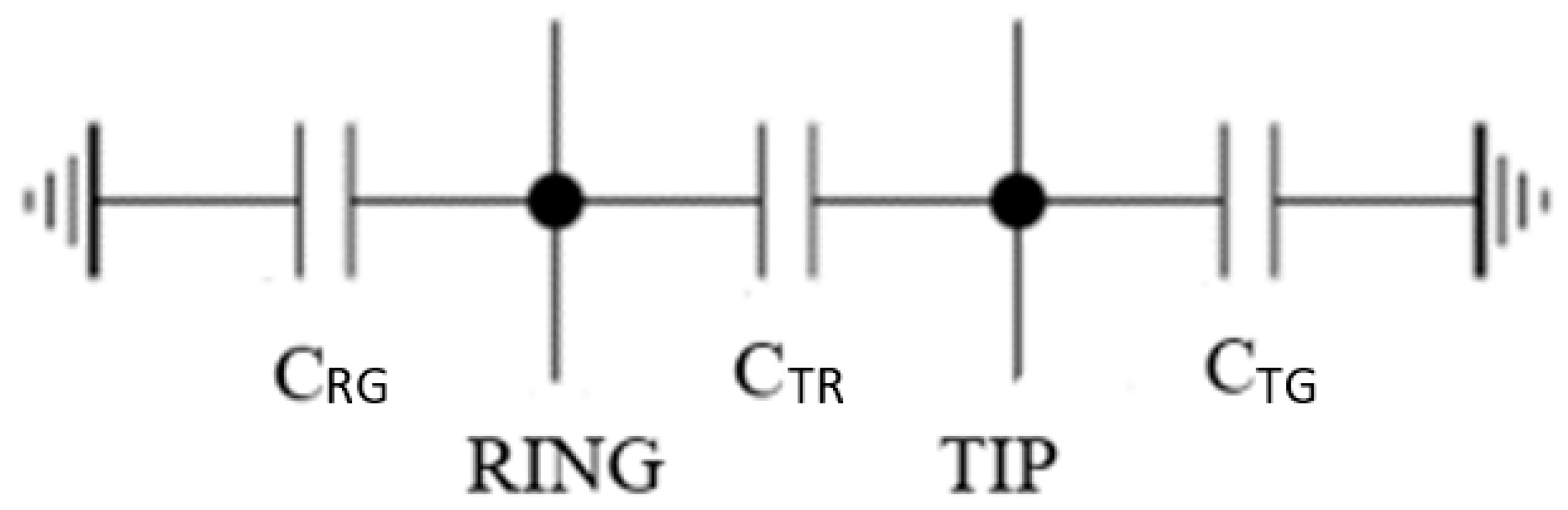
The first parameter is represented by foreign voltages (AC and DC). Foreign voltages may occur differentially between Tip-Ring (TR), between Tip/Ring-Ground (TRG) in a common mode or between Tip-Ground (TG) and between Ring-Ground (RG) in a single-ended mode. The second parameter presents the Capacity (C) determined in relation to three sections (Figure 1):
- Tip-Ground (CTG),
- Tip-Ring (CTR),
- Ring-Ground (CRG).
3.1. Definition of Ranges for Evaluating Test Parameters
The criteria for evaluating test parameters are built-up on the basis of available valid specifications [32,33,34,35]. Since the applied research aim was carried out in a cooperation with the telecommunications network operator and service provider, the required implementation output, derived from evaluated test parameters in connection with their defined ranges and tolerances, is created and determined on the basis of DSL service demands, standard homogeneous symmetric line requirements and expert discussions. The evaluated and analyzed parameters provided by the MELT test output are foreign voltages (AC and DC) and capacity. Categories of the quantities for further processing as follows:
- Direct Current (DC) voltages between sections RG, TR and TG,
- Alternating Current (AC) voltages between sections RG, TR and TG,
- Capacity (C) between sections RG, TR and TG.
In [32], the Tip section may be referred to as “wire A”, the Ring section as “wire B” and the Ground is designated for the reference point. For the correct evaluation of test parameters, it is necessary to define the allowed ranges and permitted tolerances of individual quantities. A possible value range consists of the allowed range, where the value of the quantity does not affect the quality of service, and permitted tolerances, where the value may (but does not necessarily) affect the quality of the transmitted service.
The first quantity involves DC foreign voltages. Row 1 in Table 1 specifies the allowed range of DC foreign voltages between all sections [33].
The permitted tolerances are defined for three possible cases, specifying the possible cause of the failure [34,35]:
Particular values of permissible tolerances for each case are presented in Rows 2, 3 and 4 in Table 1, correspondingly.
The second quantity includes AC foreign voltages. In this case, the defined value ranges are the same as for DC voltages. The only difference is the defined rms voltage Vrms unit.
The third quantity represents the C capacity. Its allowed values are introduced in Row 5 in Table 1. Important sections for analysis are the Ring-Ground and Tip-Ground sections. The Tip-Ring section is evaluated for the same defined range and does not affect the quality of service at excess.
In this case, permitted tolerances are also defined (Row 6 in Table 1). In the first case, the value exceeds the limit range, and in the second, the value is below the limit range. In both cases, there may be a malfunction of the open wire, i.e., the short circuit. If a different capacity value (other than within the permitted tolerance) occurs, the given wire is open (connected for a short time).
3.2. Process of Evaluation of MELT Test Parameters and Analysis of Quantities
The process begins with the MELT test procedure realized by means of Nokia test software 5520 AMS GUI, version 9.7.05-426853. The evaluation of MELT test parameters consists of comparing the quantity value with the values given in the previous Table 1. In total, three quantities (DC, AC and C) are evaluated between three sections (RG, TR and TG), such that the total number of executed quantities is nine. The analysis of quantities consists of determining whether a given value of the quantity meets a specified allowed range, is within the permitted tolerance or is outside an expected range. If the value of the quantity is within the permissible tolerance or outside the specified range, the possible cause of the failure can be determined.
For the purposes of evaluation of the MELT test parameters and analysis of quantities, we realized a mobile application in the environment of the Android operating system [36] which can evaluate MELT test parameters and analyze appropriate homogeneous symmetric lines for DSL service provision.
4. Mobile Application Functionality for Evaluation of Melt Test Parameters and Analysis of Homogeneous Symmetric Lines
For technicians of network operators and service providers, a mobile application is an auxiliary tool for diagnosing and solving faults in metallic access networks. This mobile application, as mentioned, has been designed and optimized for use in mobile devices working with the Android operating system [36]. The main and most important functionality of this mobile application is to evaluate MELT test parameters and analyze any real deployed homogeneous symmetric line for DSL service provision. Since no identical or similar mechanism and/or application has been found in any specialized literature or resources, it can be considered as a new possibility for evaluating measured parameters of a metallic transmission medium and for analyzing DSL service provision on metallic access networks.
4.1. Algorithm of Evaluation of MELT Test Parameters and Analysis of Quantities
The algorithm of evaluation for MEST test parameters is based on comparing the value of a particular evaluated quantity with a specified value. First, the value of quantities is determined by DSL service demands, standard homogeneous symmetric line requirements and expert discussion. This value is prepared within the algorithm for comparison with the acquired measured value of quantities. Second, a GOOD/WARNING/FAIL message statement is performed based on this comparison. Finally, the overall evaluation of the homogeneous symmetric line is subsequently based on the PASS and FAIL message statement. This extract serves for the overall parameter evaluation of the tested homogeneous symmetric line. The structure of the mobile application consists of the main screen, where a list of nine quantities (three quantities, each tested on three sections) is prepared, to which values of quantities can be entered. After entering them, the evaluation of MELT test parameters and analysis of quantities starts. There is a button called Evaluate in the right corner. After pressing it, an overall evaluation of line parameters and analysis of specific quantities is performed.
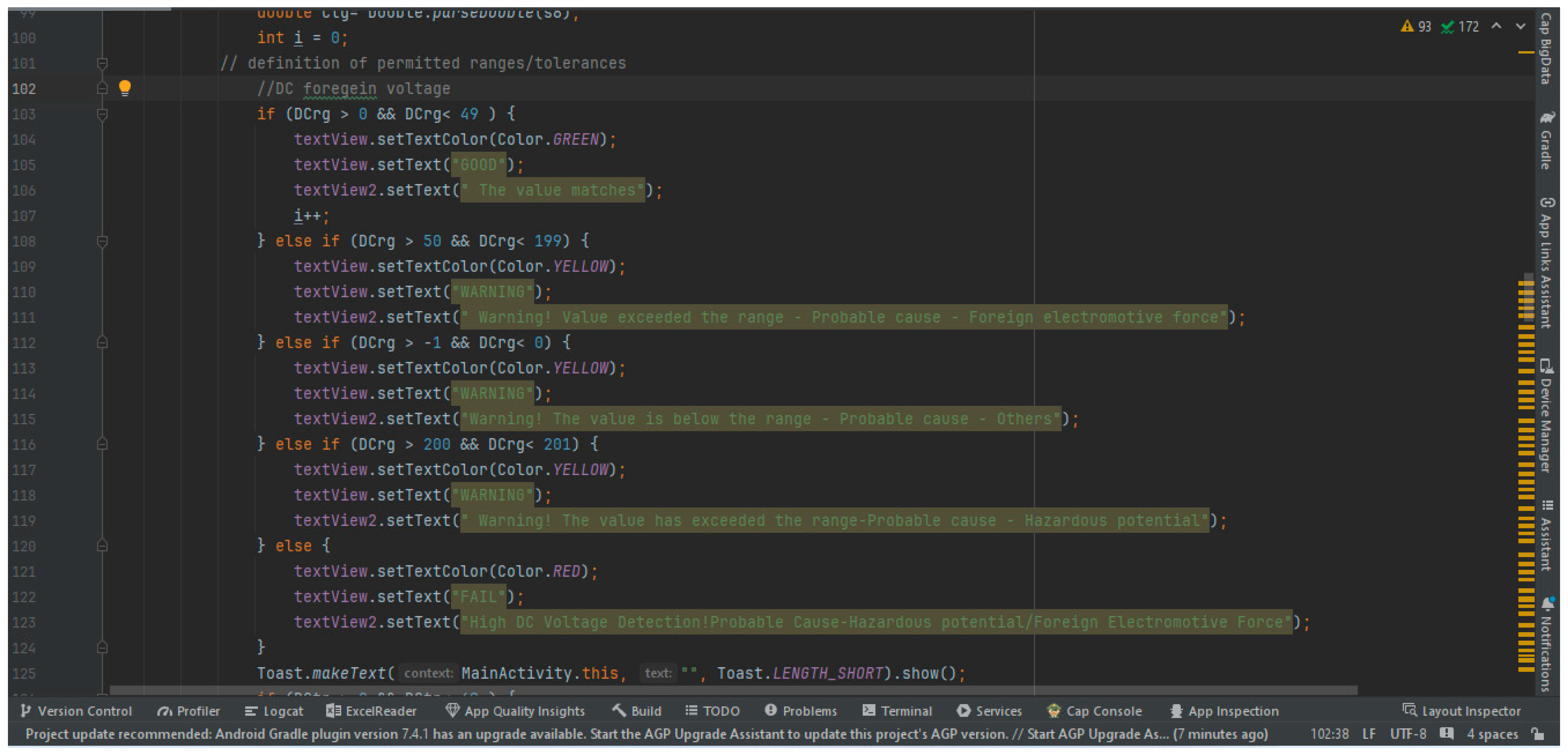
Figure 2 illustrates the structure of the comparison involving the ranges of evaluated parameters and analyzed quantities. As can be seen, the allowed ranges and permitted tolerances for DC foreign voltages, specifically for DC foreign voltages between Ring -Ground (RG), are defined and realized in Lines 102–123. A condition for the allowed range corresponding to Row 1 in Table 1 is realized and evaluated in Lines 103–106, where two text messages are considered. For this condition, the main text message (GOOD) is green colored and the second text message comments closely on the evaluation result. Subsequently, conditions for the permitted tolerances corresponding to Rows 2–4 in Table 1 are defined and evaluated in Lines 108–123. For these conditions, the main text message is yellow (WARNING) or red (FAIL) colored and the second text messages comment closely on appropriate evaluation results. Because the total number of quantities is nine, they must be analyzed in an appropriate and corresponding way in this program.
As mentioned above, three quantities (DC foreign voltage, AC foreign voltage and C capacity) are evaluated and analyzed for three distinct types of sections (RG, TR and TG). The algorithm consists of comparing the value of a particular evaluated quantity with the range defined in the application according to Table 1. The evaluation process begins by loading the measured value of a quantity from the homogeneous symmetric line. After entering the measured values of all relevant quantities, the evaluation process starts in the mobile application. This consists of a statement of reports evaluating quantities and reports that analyze these quantities.
The structure of the MELT test parameter evaluation shall include:
- Text messages—GOOD (quantity in the allowed range), WARNING (quantity in permitted tolerances) or FAIL (out of the allowed range and permitted tolerances).
- Comments on the evaluated measured values of quantities and on possible causes of the failure (in the case of the range excess).
The resulting evaluation consists of the PASS text message if most of the parameters meet the specified criteria or the FAIL text message if several line parameters are above or below the range. Since no literature or other resources explicitly specify how the overall evaluation of the MELT test parameters should be conducted, it has been defined that at least half of the evaluated values of quantities must meet the criteria for a favorable evaluation of the MELT test parameters.
4.2. Evaluation of MELT Test Parameters in the Mobile Application
In this section, the functionalities of the mobile application for evaluating MELT test parameters and for analyzing appropriate homogeneous symmetric lines for DSL service provision are introduced. The mobile application is installed on a tablet that runs with the Android operating system. The application is called “Evaluation of the MELT test”.
Since the test parameter data come from a test software tool that is reserved only for the telecommunication operator, the data obtained from the test measurements are inadaptable in a different area than the created mobile application from a security viewpoint. They are not transferred directly from the test software tool to the mobile application. Data from the test software tool are available as an export in a specific CSV file format. In this way, data are entered into the mobile application that is not available for the commercial market. The mobile application can recognize uncorrected data entry and warns the user to enter corrected data. Data in the mobile application are evaluated once, without any memory recording and without any transmitting, so they cannot be misused. After launching the mobile application, the user can see the main page of the application with nine quantities (see Section 3.2). The measured values of quantities are loaded by the virtual keypad to the corresponding quantity. In total, three categories of quantities (DC/AC foreign voltages and C capacity) are evaluated, where the first quantity from the group is also listed the unit that characterizes the quantity. After entering all the parameters, it is necessary to click on the Evaluate button in the upper right corner.
After clicking on the button, the results of the evaluation of the measured test parameter values and analysis of individual quantities, as well as the overall evaluation of the MELT test, are displayed at the bottom of the screen. The evaluation of measured values consists of GOOD/WARNING/FAIL message statements, where the GOOD message is colored in green, WARNING in yellow and FAIL in red. The analysis of the quantity consists of the extraction of the report; for example, “The quantity corresponds to the range”. If a measured value is evaluated by the WARNING/FAIL message, the possible cause of the failure is also indicated. The final evaluation of the MELT test includes two types of messages, “PASS... Most of the line parameters correspond to the established criteria, no intervention is required.” or “FAIL... Multiple line parameters have exceeded the range, are above or below range. Check the parameters and take additional measurements!”
For verification of the mobile application’s functionalities, we performed experiments and tests on several real deployed homogeneous symmetric lines utilized in real metallic access network infrastructure of one of Slovakia’s telecom network operators. Testing and demonstration of the proposed application took place directly at the network operator side using a test software tool from Nokia (Alcatel-Lucent). Then, the test method was selected (MELT). The MELT test is possible to realize in two ways (testing collective and testing group parameters). The difference is contained in the output display. The standard MELT test procedure should not take more than 20 s from the start-up. After the MELT test, it is possible to view measured test parameter values and export them (CSV format). Examples of the Nokia Sample test software and MELT test parameters are presented in Figure 3 and Figure 4. In Figure 3, the procedure for selecting the MELT option in the Nokia test software is shown. On the left side, the port for testing is selected and appropriate possibilities are displayed by the right mouse button. After the “Actions” option is confirmed, the “Metallic Ended Line Test” option offers two choices (Group Test and Collective Test) differing only in the output display. The “Collective Test” option provides a more detailed output of the tested line parameters. In Figure 4, results for the selected port are displayed with a complete list of MELT test parameters. The upper part contains information about the test progress and the test line; the lower part involves the MELT tested line parameters appropriate for individual sections (RG, TR and TG) together with their classification. Subsequently, parameters—DC/AC foreign voltages and C capacity—are selected and used to evaluate the MELT test parameters and to analyze quantities.
As examples, the following tables (Table 2 and Table 3) present the test parameter values we received after execution of the MELT test procedure by means of the measuring Nokia test software on the real deployed homogeneous symmetric lines of the network operator.
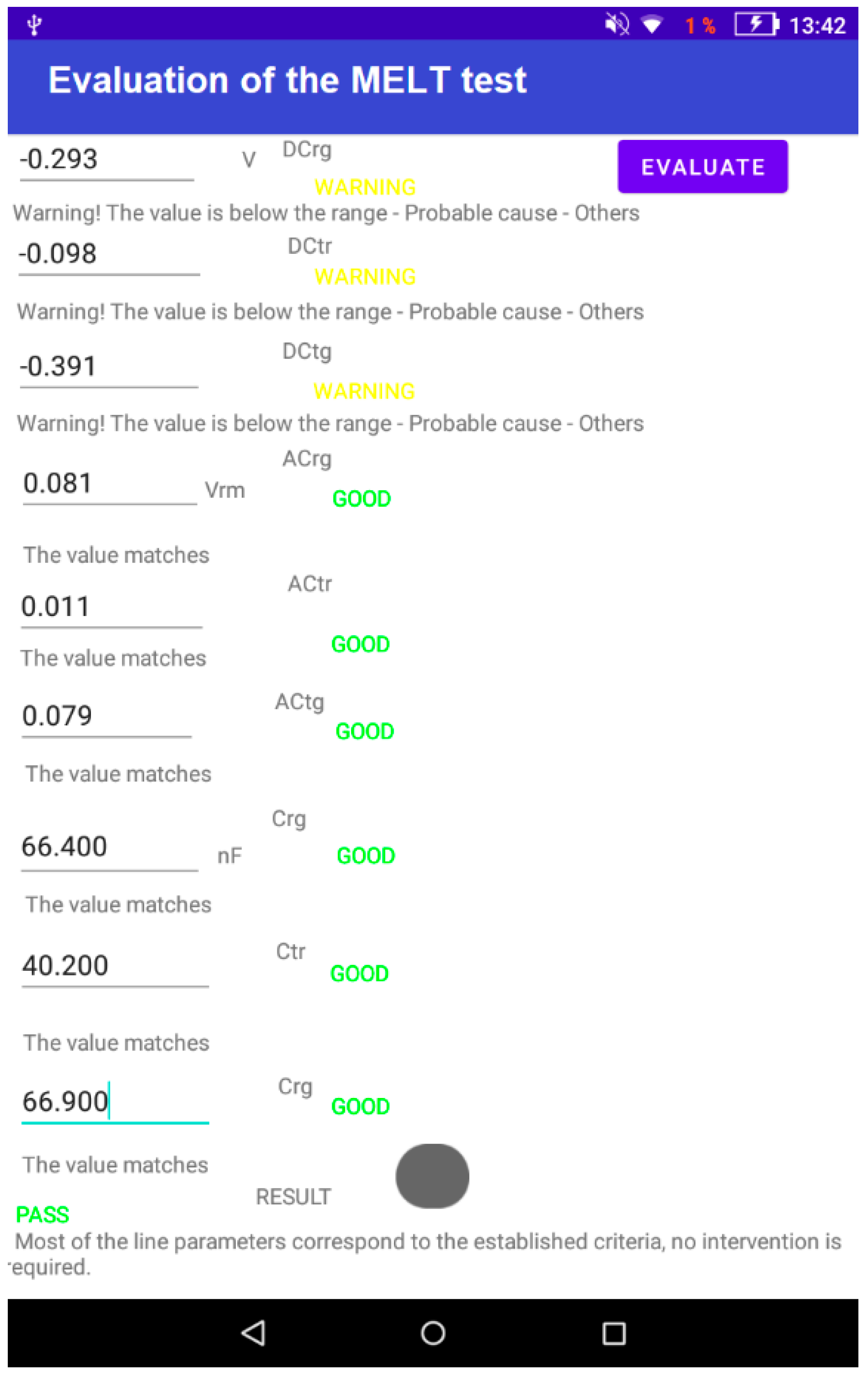
From the above values, the mobile application can assume that the line on which the testing was conducted should be evaluated as overall satisfactory, but only some of the quantities are within the permitted tolerances. To verify the correctness, the mobile application is launched for verifying whether this assumption is correct.
As can be seen in Figure 5, the WARNING message is displayed at the evaluated values of DC foreign voltages between all three sections, RG, TR and TG. Moreover, an unspecified class of foreign voltage levels has been identified as the possible cause of the failure, since all values of DC foreign voltages are below the specified range. Overall, the mobile application evaluated the first tested line with the PASS message. Based on the obtained output, we can confirm that the first tested line #1 is able to maintain DSL service provision without major restrictions. The second tested line #2 has the following parameters (Table 3).
After comparing the values with the reference values (Table 1), the mobile application can assume that the tested line should be evaluated by the PASS message. After loading the measured values into the mobile application, it can verify whether this assumption is correct.
As can be seen in Figure 6, only the value of the DC foreign voltage between the Tip-Ring section was evaluated by the WARNING message. Overall, the second tested line was evaluated by the PASS message, which meets the assumption stated above, and the second line #2 is also suitable for DSL service provision without major restrictions.
5. Conclusions
Metallic access networks utilizing homogeneous symmetric lines as a transmission medium are still in the center of interest of network operators. The utilization of metallic homogeneous lines in future access networks is expected, with necessary advances in different signal processing techniques in DSL technologies for improving their service provision in heavy environmental conditions. For this aim, appropriate simulation models of metallic transmission media can be effectively exploited. Moreover, measurements on metallic homogeneous symmetric lines, together with the evaluation of measured test parameter values, play a significant role also in current days. In mutual cooperation, the analysis of availability on actual homogeneous symmetric lines for DSL service provision can be realized.
In this contribution, we present a created mobile application for evaluating MELT test parameters and for analyzing homogeneous symmetric lines for DSL service provision. The evaluation of MELT test parameters consists of comparing the measured values of the requested parameters of a metallic transmission medium with the standardized values. The analysis of quantities consists of determining whether a given quantity meets a specified allowed range, is within the permitted tolerance or is outside an expected range. A novelty of this work is presented by the innovative mobile application, realized in the environment of an Android operating system, that can evaluate MELT test parameters, diagnose connection failures, solve potential causes and analyze appropriate homogeneous symmetric lines for DSL service provision. Technicians of network operators can utilize this mobile application as a profitable tool for advanced measurements and diagnoses on actual operative homogeneous lines in metallic access networks.
In future works, we can expand this mobile application for evaluating the MELT test parameters with functionalities related to other tests (e.g., SELT and DELT) and/or for evaluating and testing of specifically provided services (IPTV, VoIP, etc.).
Author Contributions
Conceptualization, M.L. and R.R.; methodology, R.R.; software, M.L.; validation, M.L.; formal analysis, M.L.; investigation, M.L.; resources, R.R.; data curation, M.L.; writing—original draft preparation, M.L.; writing—review and editing, R.R.; visualization, M.L.; supervision, R.R.; project administration, R.R.; funding acquisition, R.R. All authors have read and agreed to the published version of the manuscript.
Funding
This work was funded by the Cultural and Educational Grant Agency MŠVVaŠ SR, grant number KEGA 034STU-4/2021 and by the Scientific Grant Agency MŠVVaŠ SR, grant number VEGA 1/0322/24.
Institutional Review Board Statement
Not applicable.
Informed Consent Statement
Not applicable.
Data Availability Statement
Data are contained within the article.
Conflicts of Interest
The author declares no conflicts of interest. The funders had no role in the design of the study; in the collection, analyses, or interpretation of data; in the writing of the manuscript, or in the decision to publish the results.
References
- Keukeleire, N.; Hesmans, B.; Bonaventure, O. Increasing broadband reach with hybrid access networks. IEEE Commun. Stand. Mag. 2020, 4, 43–49. [Google Scholar] [CrossRef]
- Mercian, A.; Gurrola, E.I.; Aurzada, F.; McGarry, M.P.; Reisslein, M. Upstream polling protocols for flow control in PON/xDSL hybrid access networks. IEEE Trans. Commun. 2016, 64, 2971–2984. [Google Scholar] [CrossRef]
- Mazzenga, F.; Giuliano, R. A worst-case performance analysis of approximated zero forcing vectoring for DSL systems. Information 2018, 9, 108. [Google Scholar] [CrossRef]
- Q4/15; Broadband Access over Metallic Conductors. Study Group 15. International Telecommunication Union: Geneva, Switzerland, 2022.
- Sharma, M.; Verdyck, J.; Lefevre, Y.; Tsiaflakis, P.; Moonen, M. MIMO per-tone equalizer design for long reach xDSL. IEEE Open J. Commun. Soc. 2022, 3, 51–64. [Google Scholar] [CrossRef]
- Mazzenga, F.; Giuliano, R. Analytical framework for preliminary planning of very high-speed digital subscriber line access networks. Information 2017, 8, 86. [Google Scholar] [CrossRef]
- Statesmen, D.; Ödling, P.; Zhang, C.; Mecklenbräuker, C. Network modeling and performance evaluation for G.fast. IEEE Access 2021, 9, 164026–164036. [Google Scholar] [CrossRef]
- Róka, R. The utilization of the vectored DMT for the FEXT-free signal transmission by means of the VDSL technology. In Proceedings of the 15th International Workshop on Systems, Signals and Image Processing, Bratislava, Slovakia, 25–28 June 2008; pp. 299–302. [Google Scholar] [CrossRef]
- Zhang, Y.; Zhang, R.; Zhang, J.; Bai, T.; Al Rawi, A.; Moonen, M.; Hanzo, L. Far-end crosstalk mitigation for future wireline networks beyond G.mgfast: A survey and an outlook. IEEE Access 2020, 8, 9998–10039. [Google Scholar] [CrossRef]
- Róka, R.; Urminský, J. Experimental measurements for verification of the parametric model for reference channels in the real PLC environment. J. Electr. Eng. 2008, 59, 146–152. [Google Scholar]
- Skaljo, N.; Begović, A.; Goran, N.; Turajlić, E. On possibilities for improvements of xDSL troubleshooting testing. In Proceedings of the International Conference on Systems, Signals and Image Processing, Osijek, Croatia, 5–7 June 2019; pp. 139–143. [Google Scholar] [CrossRef]
- Ali, K.M.; Messier, G.G.; Lai, S.W. DSL and PLC co-existence: An interference cancellation approach. IEEE Trans. Commun. 2014, 62, 3336–3350. [Google Scholar] [CrossRef]
- Engelen, A.; Weling, N. PLC-xDSL dynamic interference mitigation. In Proceedings of the IEEE International Symposium on Power Line Communications and its Applications, Aachen, Germany, 26–27 October 2021; pp. 25–30. [Google Scholar] [CrossRef]
- Róka, R. Modeling of environmental influences at the signal transmission by means of the VDSL and PLC technologies. Int. J. Commun. Netw. Inf. Secur. 2009, 1, 6–13. [Google Scholar]
- Róka, R. The environment of fixed transmission media and their negative influences in the simulation. Int. J. Math. Comput. Simul. 2015, 9, 190–205. [Google Scholar]
- Galli, S.; Kerpez, K.J.; Mariotte, H.; Moulin, F. PLC-to-DSL interference: Statistical model and impact on VDSL2, Vectoring, and G.fast. IEEE J. Sel. Areas Commun. 2016, 34, 1992–2005. [Google Scholar] [CrossRef]
- Róka, R. The design of a PLC modem and its implementation using FPGA circuits. J. Electr. Eng. 2009, 60, 43–47. [Google Scholar]
- Oksman, V.; Strobel, R.; Wang, X.; Wei, D.; Verbin, R.; Goodson, R.; Sorbara, M. The ITU-T’s new G.fast standard brings DSL into the gigabit era. IEEE Commun. Mag. 2016, 54, 118–126. [Google Scholar] [CrossRef]
- Al-Naffouri, T.Y.; Quadeer, A.A.; Caire, G. Impulsive noise estimation and cancellation in DSL using orthogonal clustering. In Proceedings of the IEEE International Symposium on Information Theory Proceedings, St. Petersburg, Russia, 31 July–5 August 2011; pp. 2841–2845. [Google Scholar] [CrossRef]
- Bai, T.; Zhang, H.; Zhang, J.; Xu, C.; Rawi, A.; Hanzo, L. Impulsive noise mitigation in digital subscriber lines: The state-of-the-art and research opportunities. IEEE Commun. Mag. 2019, 57, 145–151. [Google Scholar] [CrossRef]
- Zafaruddin, S.M.; Chapala, V.K.; Prasad, S. Dual sensor impulse noise cancellation for downstream DSL systems. IEEE Trans. Commun. 2021, 69, 3260–3273. [Google Scholar] [CrossRef]
- Punchihewa, A.; De Silva, A. Tutorial on IPTV and its latest developments. In Proceedings of the International Conference on Information and Automation for Sustainability, Colombo, Sri Lanka, 17–19 December 2010; pp. 45–50. [Google Scholar] [CrossRef]
- Al-Jobouri, L.; Casu, F.; Fleury, M.; Cabrera, J. Video over DSL with LDGM codes for interactive applications. Computers 2016, 5, 9. [Google Scholar] [CrossRef]
- El-Mottaleb, S.; Métwalli, A.; Chehri, A.; Ahmed, H.; Zeghid, M.; Khan, A. A QoS classifier based on machine learning for next-generation optical communication. Electronics 2022, 11, 2619. [Google Scholar] [CrossRef]
- Škaljo, N.; Begović, A.; Behlilović, N. An efficient troubleshooting testing scenario for IPTV over DSL lines: Practical examples. In Proceedings of the International Conference on Systems, Signals and Image Processing, London, UK, 10–12 September 2015; pp. 233–236. [Google Scholar] [CrossRef]
- Sharma, M.; Moonen, M.; Lefevre, Y.; Tsiaflakis, P. MIMO time domain equalizer design for long reach xDSL MIMO channel shortening. IEEE Access 2020, 8, 203468–203477. [Google Scholar] [CrossRef]
- Sharma, M.; Moonen, M.; Lefevre, Y.; Tsiaflakis, P. Resource Sharing Strategies for Point-to-Multipoint Distribution in Next-Generation DSL Networks. IEEE Open J. Commun. Soc. 2023, 4, 2697–2716. [Google Scholar] [CrossRef]
- Bergel, I.; Leshem, A. The performance of zero forcing DSL systems. IEEE Signal Process. Lett. 2013, 20, 527–530. [Google Scholar] [CrossRef]
- Nishiyama, E.; Nishijima, C.; Kuwanami, K. A method for fault detecting on twisted pair cable network by use of m-sequence correlation. In Proceedings of the 30th Annual Conference of IEEE Industrial Electronics Society, Busan, Republic of Korea, 2–6 November 2004; pp. 1929–1934. [Google Scholar] [CrossRef]
- Zafaruddin, S.M.; Bergel, I.; Leshem, A. Signal processing for gigabit-rate wireline communications: An overview of the state of the art and research challenges. IEEE Signal Process. Mag. 2017, 34, 141–164. [Google Scholar] [CrossRef]
- Kerpez, K.J.; Kinney, R. Integrated DSL test, analysis and operations. IEEE Trans. Instrum. Meas. 2008, 57, 770–780. [Google Scholar] [CrossRef]
- G.996.2; Single-Ended Line Testing for Digital Subscriber Lines. International Telecommunication Union: Geneva, Switzerland, 2018.
- G.992.3; Asymmetric Digital Subscriber Line Transceivers 2 (ADSL 2). International Telecommunication Union: Geneva, Switzerland, 2009.
- TR-286; Testing of Metallic Line Testing (MELT) Functionality on xDSL Ports. Issue 1. Broadband Forum: Fremont, CA, USA, 2012.
- TR-286; Testing of Metallic Line Testing (MELT) Functionality on xDSL Ports. Issue 1, Amendment 1. Broadband Forum: Fremont, CA, USA, 2012.
- MEGA. Evaluation of the MELT test_app. Available online: https://mega.nz/folder/xG8gTJ4Z (accessed on 14 April 2024).
Figure 1.
Scheme with defined sections RG, TR and TG for the Capacity parameter.

Figure 2.
Example of the comparison involving the ranges of evaluated parameters and analyzed quantities.
Figure 2.
Example of the comparison involving the ranges of evaluated parameters and analyzed quantities.

Figure 3.
Selection of the MELT option in the Nokia test software.

Figure 4.
Display of the test result with a complete list of MELT test parameters.

Figure 5.
Evaluation of MELT test parameter values of the test line #1 in the mobile application.

Figure 6.
Evaluation of MELT test parameter values of the test line #2 in the mobile application.


Table 1.
Allowed ranges and permitted tolerances of DC foreign voltages and capacities.
| DC (RG, TR, TG) | Minimum Value | Maximum Value |
|---|---|---|
| Allowed range | 0 V | 49 V |
| Permitted tolerance | 50 V | 199 V |
| Permitted tolerance | 200 V | 201 V |
| Permitted tolerance | −1 V | 0 V |
| C (RG, TG, TR) | Minimum value | Maximum value |
| Allowed range | 0 nF | 1000 nF |
| Permitted tolerance | 1000 nF | 1100 nF |
| −3 nF | 0 nF |
Table 2.
Measured values of the first tested line #1.
| RG | TR | TG | |
|---|---|---|---|
| DC [V] | −0.293 | −0.098 | −0.391 |
| AC [Vrms] | 0.081 | 0.011 | 0.079 |
| C [nF] | 66.400 | 40.200 | 66.900 |
Table 3.
Measured values of the second tested line #2.
| RG | RT | TG | |
|---|---|---|---|
| DC [V] | 0.187 | −0.070 | 0.200 |
| AC [Vrms] | 0.107 | 0.012 | 0.109 |
| C [nF] | 17.800 | 61.200 | 17.600 |
Disclaimer/Publisher’s Note: The statements, opinions and data contained in all publications are solely those of the individual author(s) and contributor(s) and not of MDPI and/or the editor(s). MDPI and/or the editor(s) disclaim responsibility for any injury to people or property resulting from any ideas, methods, instructions or products referred to in the content. |
© 2024 by the authors. Licensee MDPI, Basel, Switzerland. This article is an open access article distributed under the terms and conditions of the Creative Commons Attribution (CC BY) license (https://creativecommons.org/licenses/by/4.0/).
Share and Cite
MDPI and ACS Style
Lichý, M.; Róka, R. The Perspective of Metallic Access Networks Based on MELT Parameter Measurements on Homogeneous Symmetric Lines. Appl. Sci. 2024, 14, 3720. https://0-doi-org.brum.beds.ac.uk/10.3390/app14093720
AMA Style
Lichý M, Róka R. The Perspective of Metallic Access Networks Based on MELT Parameter Measurements on Homogeneous Symmetric Lines. Applied Sciences. 2024; 14(9):3720. https://0-doi-org.brum.beds.ac.uk/10.3390/app14093720
Chicago/Turabian StyleLichý, Marek, and Rastislav Róka. 2024. "The Perspective of Metallic Access Networks Based on MELT Parameter Measurements on Homogeneous Symmetric Lines" Applied Sciences 14, no. 9: 3720. https://0-doi-org.brum.beds.ac.uk/10.3390/app14093720
Note that from the first issue of 2016, this journal uses article numbers instead of page numbers. See further details here.