
Magnetorheological Fluid-Based Haptic Feedback Damper


Department of Instrumental and Electrical Engineering, Xiamen University, Xiamen 361000, China
*
Author to whom correspondence should be addressed.
Appl. Sci. 2024, 14(9), 3697; https://0-doi-org.brum.beds.ac.uk/10.3390/app14093697
Submission received: 8 April 2024
/
Revised: 19 April 2024
/
Accepted: 24 April 2024
/
Published: 26 April 2024
(This article belongs to the Section Applied Physics General)
Abstract
:Damping involves the various frictional and other obstructive effects that attenuate free vibration. For a long time, people have mainly used it to make various dampers to reduce mechanical vibration and consume kinetic energy. It is widely used in fields such as aerospace, automotive, and consumer electronics. These dampers mainly act on mechanical structures. In recent years, with the rapid development of novel human–machine interaction methods and force/tactile feedback technology, the damper has begun to act on people, such as when a person interacts with a robot and their force is applied to a structure with damping. This type of damper requires variable damping, and the amount of variation is controlled by the magnitude of human action. This study used magnetorheological fluid (MRF) instead of traditional damping fluids, such as silicone oil, sesame oil, and mechanical oil. Magnetorheological fluid is a controllable fluid with magnetorheological effects, and its viscosity (hardness) can be changed by changing the nearby magnetic field. This study took the design of variable damping keyboard buttons with haptic feedback as an example to study the electromagnetic and dynamic models of variable dampers based on magnetorheological fluids. The experimental setup was designed and used to verify the haptic effectiveness of the scheme, which can be applied to the development of other haptic dampers that require variable damping.
1. Introduction
Haptic feedback is a crucial perceptual modality, with its technology extensively employed in remote-sensing robotic systems, tele-surgery, and other fields [1]. Traditional haptic feedback systems primarily utilize motor drives or other actuating mechanisms, which are often considered as dampers. In current engineering and scientific research fields, traditional damping systems often suffer from problems such as limited adjustment range and slow response speed [2,3]; therefore, the design and construction of a damper that can overcome these difficulties is of great significance to the development of haptic feedback technology.
A magnetorheological fluid comprises magnetic particles, carrier fluids, and stabilizers [4], whose flow properties change significantly under the influence of a magnetic field. Specifically, in the absence of an external magnetic field, an MRF behaves as a low-viscosity Newtonian fluid [5]. However, under the influence of a strong magnetic field, an MRF is transformed into a Bingham fluid [6] characterized by high viscosity and low fluidity. The increase in viscosity imparts solid-like properties to the fluid, and this occurrence is termed the magnetorheological effect [7,8]. Utilizing this effect, magnetorheological fluids (MRFs) have many applications in various fields, such as in the industrial sector, where external magnetic fields can be manipulated to regulate local flow resistance and pressure, thus maintaining bearing clearance under varying loads and enhancing bearing work stability [9,10]. In the healthcare domain, MRFs can be employed for drug delivery or improvement of the tactile feedback experience for distant surgery [11,12,13]. In finishing processes, the incorporation of abrasive particles within an MRF results in a magnetorheological polishing fluid that forms regular micro-abrasive heads under gradient magnetic fields that remove minute surface material from workpieces [14].
Thanks to its controllable and rapidly adjustable characteristics, applying the magnetorheological fluid to dampers may be able to provide an effective solution to the above problem [15,16]. For example, in vehicle suspension systems, magnetorheological dampers can adjust the damping force in real time according to road conditions and vehicle speed to improve the driving stability and comfort of the driver and passengers [17]. In the vibration control of cable-stayed bridges, magnetorheological dampers can effectively suppress the vibration of the cable-stayed cables to improve the safety and service life of the bridges [18].
However, although research on magnetorheological fluids (MRFs) has achieved certain results, applying them to dampers still encounters many challenges and difficulties, such as the difficulty of precise control of the magnetic field applied to the MRFs, the influence of the MRF viscosity on the overall temperature, and the difficulty of decreasing the fabrication cost [19]. For this reason, this study explored the application of magnetorheological fluids in the field of dampers using a keyboard as an example. A keyboard is a common input device in which each key can be considered as a damper; thus, a keyboard was a capable vehicle for testing the magnetorheological fluid damper designed in this study. Among the traditional keyboards, membrane keyboards operate with low noise but are not good enough in terms of haptic response [20]; mechanical keyboards can provide a lot of haptic feedback through key displacement but add noise and monotonous tactile sensation. Moreover, the key damping force of both types of keyboards is fixed at the factory and cannot be adjusted. To address the limitations of traditional keyboards, we used magnetorheological fluids to change their damping force to increase the haptic interaction between humans and machines.
In this study, a keyboard designed based on the magnetorheological fluid damper used a permanent magnet as the output unit of the magnetic field. By adjusting the distance between the magnet and the magnetorheological fluid, it could regulate the viscosity of the magnetorheological fluid. Thus, this simplified the control of the magnetic field and avoided the effect of the temperature change of the electromagnet on the viscosity of the magnetorheological fluid. By applying this magnetorheological fluid-based damper design to a keyboard, the feedback from keyboard users could illustrate the usability of this damped keyboard and reflect the modulation effect of the damper designed in this study. Thus, it could somewhat illustrate the application prospect of this kind of damper in the field of consumer electronics and haptic devices, and inspire people to apply it in more and more extensive fields.
This paper is organized as follows. Section 2 gives the system modeling and theoretical analysis. The feasibility of the proposed scheme is theoretically analyzed. Section 3 gives the system construction and Section 4 gives the psychophysical experiments for testing the usability of the device. The experimental results verified that dampers with variable damping force based on magnetorheological fluids can be used in haptics. Section 5 gives the conclusions.
2. Theoretical Analysis and Simulation
Using the fluid continuity equation and momentum equation, a fluid dynamics model was established. The model calculated the damping force of the magnetorheological fluid when flat-leaf flow occurred under the influence of a magnetic field. A finite element simulation verified the design accuracy of the magnetic field strength, which decreased with the axial distance of a NdFeB magnet array. Additionally, simulations were performed to ascertain the yield stress and viscosity of the Bingham fluid at the base of the button, thereby verifying the correctness of the theoretical computation from the fluid dynamic model.
2.1. Fluid Mechanics Analysis
As mentioned before, a magnetorheological fluid, under the influence of an applied magnetic field, transitions into a Bingham fluid state [21]. Conversely, in areas without an applied magnetic field, it behaves as a Newtonian fluid. In this study, the NdFeB magnet and the magnetorheological fluid demonstrated axisymmetric divisions. We therefore focused on one-quarter of the key area to investigate the distribution of magnetorheological fluid states under the influence of the magnetic field, as demonstrated in Figure 1.
Upon pressing a button, the nitrile rubber film was compressed downward, triggering deformation and causing the fluid beneath the button to flow downward and laterally. Given the button’s small, spherical base, we did not account for extrusion stress in our calculations. The keyboard box device confined the magnetorheological fluid between two plates. Assuming that the length (L) and width (W) of these two plates greatly surpassed the height (B), this flow could be considered a plane Poiseuille flow [22], with coordinates positioned at the midpoint between the two plates, as demonstrated in Figure 2.
The fluid continuity equation is given by
where u, v, and w are the flow velocities of the fluid on the x-, y-, and z-axes.
The momentum equation on the x-axis is given by
where is the density of the fluid and p is the pressure acting on the cross-section of the fluid.
If the fluid behaves as a Newtonian fluid in the absence of an applied magnetic field [23], substituting Equation (1) into Equation (2) yields
Substituting the boundary condition when and into the equation yields
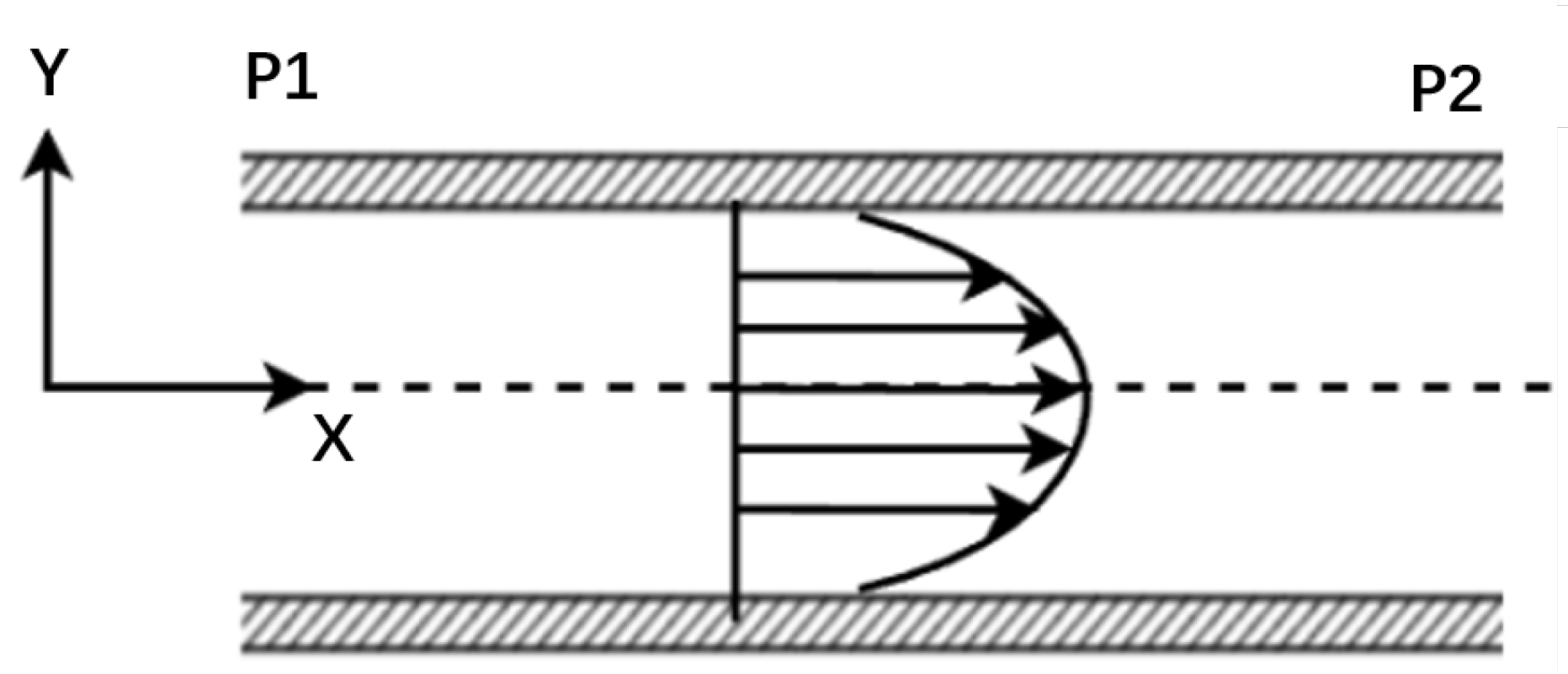
This represents the general solution for the planar Poiseuille flow of a Newtonian fluid induced by a pressure gradient, which exhibits a parabolic velocity profile, as demonstrated in Figure 3. Moreover, we need to calculate the maximum velocity corresponding to the vertex of the parabola:
From this, the flow rate of the Newtonian fluid per unit time is determined using
For a Bingham fluid with an applied magnetic field, and considering the boundary condition when and , we can calculate
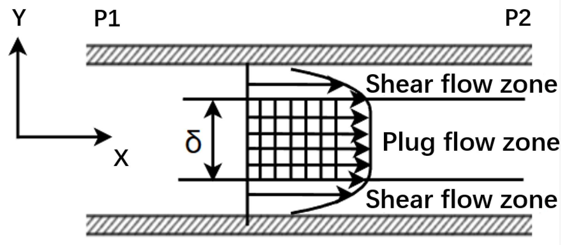
Observably, there is a constant speed region within the Bingham fluid known as the plug flow region, denoted by , which is the height of this plug flow zone. The velocity distribution of a Bingham fluid is shown in Figure 4.
According to Equations (7)–(9), the flow rate of the Bingham fluid per unit time is calculated using
Assuming the fluid velocity is V, the flow rate per unit time of the magnetorheological fluid between two plates is calculated using
Simultaneously solving Equations (6), (10), and (11), we find the pressure gradients for both Newtonian and Bingham fluids, which are represented as and , respectively:
where c is a constant that can be adjusted according to specific circumstances in the range [2, 3]. The damping force generated due to the pressure difference is calculated as follows:
Substituting Equations (12)–(14), we can calculate the damping forces of both the Newtonian fluid and Bingham fluid , respectively:
The total damping force F is the sum of the two:
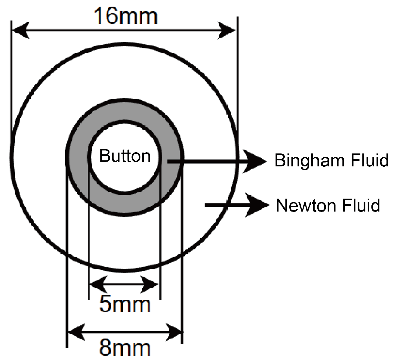
The designed magnetorheological fluid keyboard device sealed the magnetorheological fluid in a nitrile rubber film and placed it in the keyboard box using an 8 mm × 8 mm specification NdFeB magnet, the key shaft was a cylindrical shape with a diameter of 5 mm, and the bottom end was hemispherical. The damping force of magnetorheological fluid operating in extrusion mode was ignored when calculating, and only the damping force in valve mode was calculated. An axial cross-sectional view of the magnetic rheological fluid state distribution around each key axis is shown in Figure 5.
We took B as 8 mm; and as mm and mm, respectively; and as mm and 4 mm, respectively; and substituted the above values into the damping force calculation formula:
The curve equation of the relationship between the shear rate and viscosity at 40 °C was
The curve equation of the relationship between shear rate and viscosity at 40 °C was
The shear rate versus viscosity curves of the MRF used in this study and the conventional silicone oil [24] damping fluid at 40 °C were plotted in the same graph, as shown in Figure 6. It can be seen that both the silicone oil and MRF exhibited shear thinning. That is, as the shear rate increased, the viscosity of both decreased, but the rate of decrease gradually slowed down. This property enabled them to maintain good fluidity at high shear rates. However, the viscosity value of the MRFs was higher than that of silicone oils over the entire range of shear rates. This means that the MRFs were able to provide a higher damping effect under the same shear conditions.
In addition, there are other emerging damping fluids, such as shear-thickening fluid (STF) [25] and electro-rheological fluid (ERF) [26]. STF mainly relies on the microstructural changes caused by shear to realize the thickening effect, and such changes enable the fluid to rapidly harden when impacted, thus absorbing energy. ERFs are similar to MRFs in that their rheological properties are altered by the action of an electric field, and the viscosity or shear stress of an ER fluid can change significantly under the action of an applied electric field. In contrast, the viscosity of silicone oil damping fluid is relatively stable, and similar to STF, its own viscosity follows the external shock changes. ERF and MRF are able to regulate the viscosity by a electromagnetic field, and thus, it is more controllable compared with the former two. Furthermore, in applications that require a fast response and reversible conversion, ERF may be more advantageous, while in applications that require precise control of vibration and shock, MRF may be more suitable.
2.2. Magnet Array Simulation
In order to investigate the relationship between the magnetic field strength and the magnet distance, the magnetic field without the current module of COMSOL6.0 is used in this study for the finite element analysis. The “Magnetic Field, No Current” interface of COMSOL’s AC/DC module allowed us to simulate the distribution of magnetic field generated by a static magnetic source, such as a permanent magnet in the absence of current flow. During the simulation process, we used the Magnetic Field, No Current module to build an accurate physical model that takes into account the geometry of the magnets, the magnetization direction and the relative positions between the magnets. By setting appropriate boundary conditions and initial conditions, we simulated the diffusion and propagation of the magnetic field in space, and the simulation results are shown in the Figure 7.
Due to the large distance between the NdFeB magnets, the magnetic field interference was minimal, and no additional shielding device was required. In addition, the magnetic field strength attenuated greatly with distance, which showed that the method of controlling the distance between the NdFeB magnet and the magnetorheological fluid in this study was feasible to adjust the magnetic field strength at the magnetorheological fluid.
We took the magnetic field strength dataset in the ordinate range of 0 mm to 20 mm at the central axis of the NdFeB magnet and plotted the magnetic field strength and distance curve, as shown in Figure 8.
2.3. Fluid Simulation
The Bingham fluid was simulated using a 3D laminar flow model. We established the relationship between the viscosity and shear rate by combining it with Equation (20) and setting the inlet velocity to 0.2 m/s and the fluid height to 8 mm. The diagram depicting the fluid velocity and viscosity sections is presented in Figure 9.
An inspection of the diagram reveals that the fluid’s velocity skirting along the wall was zero, while it progressively increases toward the center. However, this outward velocity decreased as we approached the direct center, where the viscosity was amplified due to lower speeds. This heightened viscosity made it more challenging for the button to displace the fluid laterally, subsequently increasing the damping force.
Shear data and velocity data collected from a vertical line at the fluid’s outlet were graphed into a one-dimensional curve, as revealed in Figure 10 and Figure 11, respectively. Then, one can determine the corresponding fluid viscosity at any given position in the vertical direction by substituting the shear rate value into Equation (20).
3. Experimental System Construction
The construction of the experimental setup was completed, and the control circuit to effectuate the distance adjustment was also designed. This enabled key pressing to analyze the functionality of character input into the computer keyboard. Human–machine interaction was used to confirm the optimal distance between the NdFeB magnet and the magnetorheological fluid, as perceived by users for maximum comfort.
3.1. System Architecture
The model of the magnetorheological fluid haptic feedback keyboard system employed a NdFeB magnet to generate a magnetic field, is illustrated in Figure 12, where MCU is a microcontroller for controlling the whole device; ADC is an analog-to-digital conversion module for converting the analog signal output from the pressure sensor into a digital signal for inputting into the MCU; Com is an interface for the MCU to communicate with the computer, and the serial communication interface is used here; and PWM is a pulse-width modulation signal for driving the servo.
The proximity of the NdFeB magnet to the magnetorheological fluid contained in its compartment modulated the fluid’s viscosity and yield stress. Consequently, this affected the damper force exerted by the keys. The magnetorheological fluid was housed within nitrile rubber. When a key was pressed and the force on the pressure sensor surpassed the stipulated threshold, a voltage signal was generated, realizing the function of key detection. Simultaneously, the single-chip microcomputer controlled the servo to elevate the NdFeB magnet clamping device. Thus, the strength of the magnetic field formed by the magnet at the magnetorheological fluid was changed, leading to a change in viscosity, yield stress, and the damping force experienced upon pressing the key.
3.2. 3D Design
The 3D model of the designed haptic feedback keyboard device is shown in Figure 13. The top view of the real device is shown in Figure 14, and the side view of the real device is shown in Figure 15.
The keyboard device attached the pressure sensor film to the surface of the square key, the key was limited by the key shaft, the shaft body was equipped with a round head screw, and the round head diameter was greater than the diameter of the key hole left by the keyboard box cover such that the key was not disengaged from the device. The keyboard box cover, keyboard box, and keyboard bracket were fixed with screws and knurled nuts, and the upper and lower ends of the key box were covered with nitrile rubber film to hold the magnetorheological fluid. The four servos were fixed on each side of the keyboard stand. When the servo drove the rudder disc to rotate, the screw on the side of the NdFeB magnet clamping device located in the center of the rudder disc was moved, and the magnet and the clamping device moved upward due to the action of the four-corner limit axis of the clamping device.
The keys were secured between the keyboard case and the bottom of the keyboard bracket using four smooth screws as limit axes and knurled nuts in the keyboard. During the pressing process, the magnet became stuck in the clamping device and was not prone to lateral movement. When it was necessary to adjust the damping force, the damping force level was sent to the microcontroller through the computer, and the microcontroller calculated and output a PWM wave to control the servo mechanism to rotate at a certain angle, causing the clamping device to move up and down. Through this mechanism, precise control of the damping force could be achieved within an adjustable range of 0 to 3 millimeters.
4. Psychophysical Experiments
In order to test the sense of experience of using the keyboard designed based on a magnetorheological fluid damper, two psychophysical experiments were carried out to subjectively and objectively evaluate the validity of the proposed variable-damper keyboard. The electrical setup of device is shown in Figure 16.
4.1. Experiment 1
The variable-damper keyboard device based on magnetorheological fluid needs to be user-oriented. In order to verify its usability, this experiment subjectively assessed the experience of using the device. The subjects reported the degree of comfort during using the device.
Subjects: 15 volunteers were invited to conduct the experiment, involving 8 males and 7 females. The ages of the subjects were between 20 and 23 years old, and they had normal finger skin touch, had never participated in this or other related studies, and were not clear about the purpose of the experiment.
Process: The experimental steps were as follows:
- (1)
- The distance between the permanent magnets and the magnetorheological fluid layer was adjusted separately in the four damped buttons so that the distances were graded as 0 mm, 1.5 mm, 3 mm, and no magnet (the permanent magnet was removed in one button). The configuration is shown in Table 1 and Figure 17.
- (2)
- The volunteer pressed each of the four keys until the host computer output the key value represented by the key.
- (3)
- The volunteer’s feedback on the distance between the permanent magnet and the magnetorheological fluid layer corresponding to the most comfortable key was recorded.
Results and analysis: In the feedback given by the volunteers, more than 90% of the users were able to accurately distinguish the damping force levels. The statistical results are shown in the Table 2, which show that the degree of comfort was the highest when the NdFeB magnet was 1.5 mm away from the bottom of the magnetorheological fluid. This indicates that the magnetorheological fluid damping force could effectively improve the degree of comfort of the keys. Moreover, this damping force was adjustable to meet the needs of different users.
4.2. Experiment 2
From experiment 1, it can be understood that the damping force generated by the magnetorheological fluid under the action of a proper magnetic field (regulated by controlling the distance) could increase the degree of comfort of the damped keystrokes. The results of experiment 1 are highly subjective. In order to evaluate the device more objectively, this experiment analyzed the effect of this damping force on the speed and error rate of keystroke input.
Experimental setup: The specific key configuration was based on the device in Figure 16, and the output of the corresponding characters of the four keys were defined as “abcd” (upper-left key output a, lower-left key output b, upper-right key output c, lower-right key output d). During the experiment, the volunteers input the given strings on these four keys.
Subjects: 20 volunteers were invited to participate in this experiment, involving 12 males and 8 females aged between 20 and 23 years old. The subjects had normal finger skin tactile sensation and had never participated in this type of research or other related studies, and were not sure of the purpose of the experiment.
Process: The experimental steps were as follows:
- (1)
- A string (100 characters) containing only “abcd” characters was generated, where the number of each character was equal.
- (2)
- The distance between the magnet and the magnetorheological fluid layer in the device was set to one of four random distances (0 mm, 1.5 mm, 3 mm, Non; all four keys were the same), as shown in Table 3.
- (3)
- The volunteers entered the string as fast as they could. The results were not displayed by the host computer and were stored on a data card for statistical analysis.
- (4)
- Steps 1, 2, and 3 were repeated four times. All volunteers completed the above experiment.
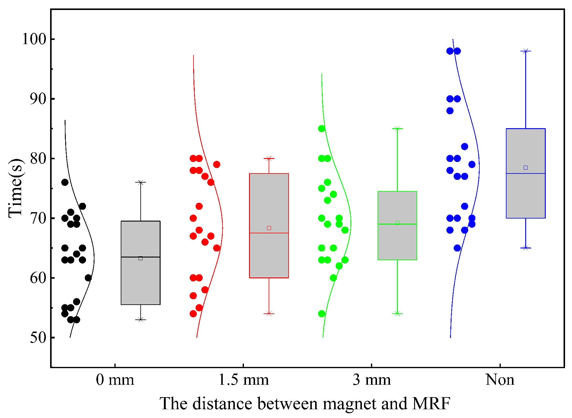
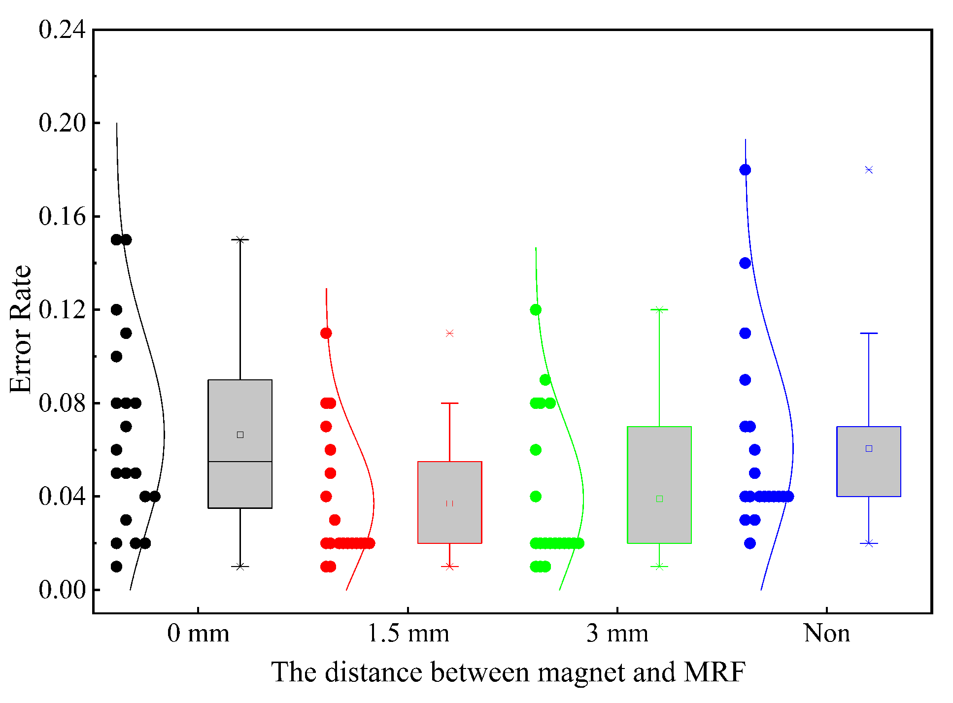
Results: The input time is shown in Figure 18 and the input error rate is shown in Figure 19. It can be seen from Figure 18 that the volunteers spent the least amount of time at a distance of 0 mm, the most amount of time in the non-magnet state, and the time spent in the other two cases was moderate and close to each other. The ANOVA showed that there was a significant difference between the four cases (F = 11.07, p < 0.01); furthermore, the t-test showed that there was no significant difference in the time spent at a distances of 1.5 mm and 3 mm (t = 1.686, p = 0.374). Figure 19 shows the error rate of inputting characters at the four magnet distances. The occurrence of errors consisted of input character errors, missed inputs, repeated inputs, etc. The volunteers made the most input errors at the 0 mm distance, followed by the non-magnet condition, and the lowest error rates in the other two conditions. The ANOVA showed a significant difference between the four cases (F = 3.357, p < 0.03); furthermore, the t-test showed that there was no significant difference in the error rates at 1.5 mm and 3 mm distances (t = 1.686, p = 0.419).
Analysis: The experimental results show that at a distance of 0 mm, the magnetic field strength was the largest, and the damping force output by the magnetorheological fluid was the largest, which made the key feel hard, the trigger stress was the largest, and the key stroke was the shortest, which led to the fastest input speed; however, the short stroke caused the rebound feedback to be small, which made the operator’s uncertainty about the input result increase, and thus, led to a high error rate. In contrast, in the non-magnet state, the damping force of the magnetorheological fluid output was the smallest, which made the key feel soft, the trigger stress was the smallest, and the key stroke was the longest, which made the input speed the slowest; however, the soft feel and the small trigger stress also caused the rebound feedback to be small, which likewise caused the operator’s uncertainty about the input result to be increased, thus causing a high error rate. For the distances of 1.5 mm and 3 mm, the damping force was moderate, which caused an excellent hand feel, and the operator input the characters at a fast speed and the error rate was low. Consequently, this experiment showed that the proposed device could improve the ease of use and input accuracy by adjusting the damping force.
5. Conclusions
In this study, we calculated and simulated the variable damping force generated by magnetorheological fluid and controlled by the distance between it and the NdFeB magnet. A prototype was implemented to examine the design usability and the tactile feedback in human–machine interaction. Users could experience different levels of damping force feedback when pressing a key, contingent on the distance between the magnet and the magnetorheological fluid. Compared with traditional mechanical keyboards (dampers), the proposed magnetorheological fluid keyboard exhibited less noise and offered a controllable hand feel, among other features. This study can be applied to other magnetorheological fluid dampers to apply variable damping in haptic applications.
In larger-scale practical applications, the use of magnetorheological fluid dampers may be limited by several factors. First, the magnetic field coupling problem is a challenge that cannot be ignored. In this study, the distribution of magnets was not compact, and thus, there was no need to consider the coupling between the magnets. However, in practical applications, the magnets may be much closer to each other, and in this case, the interaction between magnets will not be able to be ignored, which will cause control trouble; in addition, separate rudder control requires a large distance of movement, and thus, the control method in device transparency design will need to be evaluated in future work.
In this study, our research focused on a preliminary exploration of the application of magnetorheological fluid dampers, with the aim to verify their feasibility and performance through theoretical and experimental analyses. However, durability, reliability, and long-term effectiveness are important metrics for assessing the performance of dampers, and evaluating these metrics is important for accelerating the market adoption of MRF dampers. Therefore, future work will mainly focus on improving and evaluating the performance of magnetorheological fluid dampers.
Author Contributions
Conceptualization, P.K., S.L. and T.Z.; methodology, P.K.; software, P.K. and S.L.; validation, S.L.; formal analysis, P.K.; investigation, S.L.; resources, T.Z.; data curation, P.K.; writing—original draft preparation, P.K. and S.L.; writing—review and editing, P.K. and T.Z.; visualization, P.K. and S.L.; supervision, T.Z.; project administration, T.Z.; funding acquisition, T.Z. All authors read and agreed to the published version of the manuscript.
Funding
This research was funded by the Fundamental Research Funds for the Central Universities under grants 20720220084 and 20720220071.
Institutional Review Board Statement
Not applicable.
Informed Consent Statement
Not applicable.
Data Availability Statement
The original contributions presented in the study are included in the article, further inquiries can be directed to the corresponding author.
Conflicts of Interest
The authors declare no conflicts of interest.
References
- Liu, G.Y.; Liao, H.P.; Zhao, X. Haptic device and interface to reproduce force and tactile feedback of biological tissues. Sensors Actuators-Phys. 2024, 366, 115022. [Google Scholar] [CrossRef]
- Kamikawa, Y.; Okamura, A.M. Comparison Between Force-Controlled Skin Deformation Feedback and Hand-Grounded Kinesthetic Force Feedback for Sensory Substitution. In Proceedings of the 2015 IEEE International Conference on Information and Automation, Lijiang, China, 8–10 August 2015; pp. 943–948. [Google Scholar]
- Zhang, L.X.; Xiong, H.X.; Han, L.L. Design and implementation of a 6 DOF delta force feedback controller for tele-operation. IEEE Robot. Autom. Lett. 2018, 3, 2174–2181. [Google Scholar]
- Jiang, N.; Sun, S.; Ouyang, M.X. A highly adaptive magnetorheological fluid robotic leg for efficient terrestrial locomotion. Smart Mater. Struct. 2016, 25, 95019. [Google Scholar] [CrossRef]
- Jansen, Y.; Karrer, T.; Borchers, J. MudPad: Localized Tactile Feedback on Touch Surfaces. In Proceedings of the UIST’10, New York, NY, USA, 3–6 October 2010. [Google Scholar]
- Yang, T.H.; Kwon, H.J.; Lee, S.S. Development of a miniature tunable stiffness display using MR fluids for haptic application. Sens. Actuators Phys. 2010, 163, 180–190. [Google Scholar] [CrossRef]
- Ryu, S.; Yang, T.H.; Kim, S.Y. Design of a new miniature haptic button based on magnetorheological fluids. In Proceedings of the IEEE International Conference on Automation Science and Engineering (CASE), Seoul, Republic of Korea, 20–24 August 2012; pp. 121–124. [Google Scholar]
- Ishizuka, H.; Miki, N. Development of a tactile display with 5 mm resolution using an array of magnetorheological fluid. Jpn. J. Appl. Phys. 2017, 56, 06GN19. [Google Scholar] [CrossRef]
- Muzakkir, S.M.; Kumar, D. Analysis of a magnetorheological brake with a single low carbon steel disc using ANSYS. In Proceedings of the 2017 International Conference on Innovative Mechanisms for Industry Applications (ICIMIA), Bengaluru, India, 21–23 February 2017; pp. 717–719. [Google Scholar]
- Wang, W.; Li, H.; Xiao, M. Design method and experiment of robot joint flexible drive based on magnetorheological fluid. In Proceedings of the 2020 5th International Conference on Automation, Control and Robotics Engineering (CACRE), Dalian, China, 19–20 September 2020; pp. 140–144. [Google Scholar]
- Park, Y.J.; Choi, S.B. A new tactile transfer cell using magnetorheological materials for robot-assisted minimally invasive surgery. Sensors 2021, 21, 3034. [Google Scholar] [CrossRef] [PubMed]
- Park, Y.J.; Lee, E.S.; Choi, S.B. A Cylindrical Grip Type of Tactile Device Using Magneto-Responsive Materials Integrated with Surgical Robot Console: Design and Analysis. Sensors 2022, 22, 1085. [Google Scholar] [CrossRef] [PubMed]
- Zhang, L.S.; Fan, J.J.; Gu, S.X. A Novel Master Haptic Interface Based on MR-Fluids for Endovascular Catheterization. In Proceedings of the 2022 IEEE International Conference on Mechatronics and Automation (ICMA), Guilin, China, 7–10 August 2022; pp. 1269–1274. [Google Scholar]
- Tae, H.Y.; Jeong, H.K. A Minature MR Actuator with Impedance Sensing Mechanism for Haptic Application. In Proceedings of the ASME 2012, Stone Mountain, GO, USA, 19–21 September 2012. [Google Scholar]
- Fournier, J.A.; Cheng, S.H. Impact of Damper Stiffness and Damper Support Stiffness on the Efficiency of a Linear Viscous Damper in Controlling Stay Cable Vibrations. J. Bridge Eng. 2014, 19, 4. [Google Scholar] [CrossRef]
- Onozuka, Y.; Minoru, O.; Manabu, O. Rendering friction and viscosity using a wearable 4 degrees of freedom force feedback device with magnetorheological fluid clutches and pneumatic artificial muscles. In Proceedings of the IECON 2019—45th Annual Conference of the IEEE Industrial Electronics Society, Lisbon, Portugal, 14–17 October 2019; Volume 1, pp. 705–711. [Google Scholar]
- Sahin, H.; Liu, Y.; Wang, X. Full-scale magnetorheological fluid dampers for heavy vehicle rollover. J. Intell. Mater. Syst. Struct. 2007, 18, 1161–1167. [Google Scholar] [CrossRef]
- Vatandoost, H.; Norouzi, M.; Alehashem, S.M.S. A novel phenomenological model for dynamic behavior of magnetorheological elastomers in tension-compression mode. J. Smart Mater. Struct. 2017, 26, 065011. [Google Scholar] [CrossRef]
- Dutra, R.M.A.; Andrade, D. Magnetorheological fluid in prostheses: A state-of-the-art review. J. Intell. Mater. Syst. Struct. 2024, 35, 485–516. [Google Scholar] [CrossRef]
- Zhang, Y.Z.; Zou, J.J.; Wang, H.J. A single-layer less-wires stretchable wearable keyboard based on pressure switch conductive textile. Smart Mater. Struct. 2022, 31, 105008. [Google Scholar] [CrossRef]
- Zhang, J.H.; Du, W.F. A visualized flows analysis of postponed-set mortar with Bingham liquid in a single-screw extruder. In Proceedings of the 2010 International Conference on Mechanic Automation and Control Engineering, Wuhan, China, 26–28 June 2010; pp. 6287–6291. [Google Scholar]
- Smith, W.R.; Wissink, J.G. Parameterization of travelling waves in plane Poiseuille flow. J. Appl. Math. 2014, 79, 22–32. [Google Scholar] [CrossRef]
- Chen, Y.; Gao, J.; Chen, X. Comparison of the break-up behaviors of newton and shear thinning non-newton fluid in jet dispensing for LED packaging. In Proceedings of the 2015 16th International Conference on Electronic Packaging Technology (ICEPT), Changsha, China, 11–14 August 2015; pp. 1029–1032. [Google Scholar]
- Venczel, M.; Bognár, G.; Veress, A. Temperature-Dependent Viscosity Model for Silicone Oil and Its Application in Viscous Dampers. J. Process. 2021, 9, 331. [Google Scholar] [CrossRef]
- Yeh, F.Y.; Chang, K.C.; Chen, T.W. The dynamic performance of a shear thickening fluid viscous damper. J. Chin. Inst. Eng. 2011, 37, 983–994. [Google Scholar] [CrossRef]
- Gokce, C.I.; Halil, I.U. Investigation of vibration damping properties of electroactive polyanthracene/silicone oil dispersions. J. Intell. Mater. Syst. Struct. 2022, 33, 641–652. [Google Scholar]
Figure 1.
Distribution of the magnetorheological fluid states under the influence of a magnetic field.
Figure 1.
Distribution of the magnetorheological fluid states under the influence of a magnetic field.

Figure 2.
The plane Poiseuille flow distribution map.

Figure 3.
Newton fluid velocity distribution map.

Figure 4.
Bingham fluid velocity distribution map.

Figure 5.
Axial cross-sectional view of the distribution of magnetorheological fluid states around the key axis.
Figure 5.
Axial cross-sectional view of the distribution of magnetorheological fluid states around the key axis.

Figure 6.
Shear rate vs. viscosity curves.

Figure 7.
Magnetic field strength of magnet array.

Figure 8.
The magnetic field strength and distance curve.

Figure 9.
The diagram depicting the fluid velocity and viscosity sections.

Figure 10.
Velocity data collected from the vertical line of the fluid outlet.

Figure 11.
Shear rate data collected from the vertical line of the fluid outlet.

Figure 12.
The system architecture.

Figure 13.
The 3D model of the keyboard.

Figure 14.
Top view of real keyboard.

Figure 15.
Side view of real keyboard.

Figure 16.
The electrical connection of device.

Figure 17.
The experimental setup diagram.

Figure 18.
Input times under different conditions.

Figure 19.
Error rates under different conditions.


Table 1.
Configuration sheet in experiment 1.
| Location | Distance | Description |
|---|---|---|
| Upper left | 1.5 mm | Distance between MRF and magnet was 1.5 mm |
| Upper right | No magnets | No magnet under MRF |
| Bottom left | 0 mm | The magnet is adjacent to MRF |
| Bottom right | 3 mm | Distance between MRF and magnet was 3 mm |
Table 2.
Proportion of comfort feel for different buttons.
| The Distance between Magnet and Magnetorheological Fluid | Proportion (%) |
|---|---|
| 0 mm | 20 |
| 1.5 mm | 40 |
| 3 mm | 26.67 |
| No magnets | 13.33 |
Table 3.
Configuration sheet for experiment 2.
| Case | Distance | Description |
|---|---|---|
| Case 1 | 0 mm | The magnet was adjacent to MRF (all four keys) |
| Case 2 | 1.5 mm | Distance between the MRF and magnet was 1.5 mm (all four keys) |
| Case 3 | 3 mm | Distance between the MRF and magnet was 3 mm (all four keys) |
| Case 4 | No magnets | No magnet under the MRF (all four keys) |
Disclaimer/Publisher’s Note: The statements, opinions and data contained in all publications are solely those of the individual author(s) and contributor(s) and not of MDPI and/or the editor(s). MDPI and/or the editor(s) disclaim responsibility for any injury to people or property resulting from any ideas, methods, instructions or products referred to in the content. |
© 2024 by the authors. Licensee MDPI, Basel, Switzerland. This article is an open access article distributed under the terms and conditions of the Creative Commons Attribution (CC BY) license (https://creativecommons.org/licenses/by/4.0/).
Share and Cite
MDPI and ACS Style
Kang, P.; Liu, S.; Zeng, T. Magnetorheological Fluid-Based Haptic Feedback Damper. Appl. Sci. 2024, 14, 3697. https://0-doi-org.brum.beds.ac.uk/10.3390/app14093697
AMA Style
Kang P, Liu S, Zeng T. Magnetorheological Fluid-Based Haptic Feedback Damper. Applied Sciences. 2024; 14(9):3697. https://0-doi-org.brum.beds.ac.uk/10.3390/app14093697
Chicago/Turabian StyleKang, Pei, Sijia Liu, and Tao Zeng. 2024. "Magnetorheological Fluid-Based Haptic Feedback Damper" Applied Sciences 14, no. 9: 3697. https://0-doi-org.brum.beds.ac.uk/10.3390/app14093697
Note that from the first issue of 2016, this journal uses article numbers instead of page numbers. See further details here.