1. Introduction
A UAV has a simple structure and strong terrain adaptability, does not need complex operations to change the circular rotation distance of the rotor, and only requires the speed of the rotor to be changed to alter the trajectory of the flight. UAVs can also perform a wide range of movements, giving them a wide range of applications, including precision agriculture [
1], managing forest fires [
2], urban transportation [
3], crime detection [
4], express delivery [
5], etc.
Furthermore, the work by Israel Domínguez et al. [
6] demonstrates the development of a low-cost quadrotor experimental platform, specifically detailing a methodology for implementing an observer-based Proportional Integral Derivative (PID) controller. This emphasizes the critical need for practical, real-world testing environments to evaluate and refine control algorithms, ensuring their reliability under actual operating conditions despite inherent system nonlinearities and disturbances.
Addressing another sophisticated application, M. Eusebia Guerrero-Sánchez and colleagues tackled [
7] the challenge of safely and efficiently transporting cable-suspended payloads with quadrotors. Utilizing an Interconnection and Damping Assignment Passivity-Based Control (IDA-PBC) approach, they developed a robust control strategy that effectively attenuates swing, enhancing payload stability during transport. This method showcases the adaptability of UAVs to complex tasks where dynamic uncertainties and parametric variability are significant factors.
UAVs are nonlinear systems with complex dynamic behavior, so it is important to determine how to design the controller and which control strategies can reduce delays, enhance the vehicle’s robustness, increase the control quality, and reduce the control error. The existing UAV controllers can be roughly divided into linear robust controllers, nonlinear controllers, and intelligent controllers. Among them, linear robust control technology is older and more classic, and it has been widely used in many fields due to its simplicity of implementation and flexibility of parameter adjustment. However, traditional linear control methods face numerous limitations when dealing with the underactuated nonlinear characteristics [
8] of quadrotor UAVs. In order to overcome these limitations, researchers have carried out in-depth research and made improvements to this control method. For example, Ivan Gonzalez-Hernandez et al. [
9] proposed an integral-based sliding mode controller to improve the altitude control performance of quadrotor UAVs; however, it still belongs to the linear control category. Further advancing UAV control technology, Roger Miranda-Colorado and Luis T. Aguilar [
10] have developed a robust PID control methodology specifically for quadrotors that not only enhances trajectory tracking and regulation tasks but also incorporates a power reduction methodology. This novel approach uses the cuckoo search algorithm for controller-gains tuning and designs trajectories that minimize jerk, thus reducing power demand even under parametric uncertainty and aerodynamical disturbances. In addition to enhancing control precision, reducing power consumption is also critical for improving UAV efficiency and operational longevity. Roger Miranda-Colorado and colleagues [
11] have addressed this by developing a methodology that integrates trajectory design with controller-gains tuning using a cuckoo search algorithm. Their approach, employing a terminal sliding modes controller analyzed via strict Lyapunov functions, has demonstrated notable reductions in power consumption while maintaining robust performance against aerodynamic disturbances and parametric uncertainties, does not thoroughly explore more complex nonlinear control or adaptive control strategies, and shows obvious limitations when dealing with systems that have significant nonlinear characteristics and dynamic uncertainties.
Xiao Liang et al. [
12] proposed a novel nonlinear control method based on backward control, which was specially designed for the transportation system of quadrotor UAVs; it not only considers the nonlinear characteristics of the system but also addresses the challenges caused by external interference and the internal dynamic uncertainty of the system. However, it does not adapt well to unforeseen changes in system dynamics or external disturbances.
Roger Miranda-Colorado et al. [
13] discussed a variable-gain sliding mode control strategy based on Lyapunov’s theory to improve the robustness of the quadcopter to external disturbances and changes in internal parameters. However, nonlinear controllers are less flexible when it comes to modeling inaccurate or unforeseen changes in system dynamics. In contrast to intelligent or adaptive controllers, it is not suitable for systems with high uncertainty or rapidly changing conditions.
Muhammad Awais Sattar and Abdulla Ismail [
14] proposed an adaptive fuzzy PID control method that combines PID control, fuzzy logic, and an adaptive control strategy to improve the adaptability and control performance of quadrotor UAVs in complex dynamic environments. The basic motion of the quadrotor UAV was controlled, and the effectiveness of the proposed control strategy was verified via a simulation.
In the Adaptive Dynamic Reconfiguration Control (ADRC) framework, the tuning of the extended state observer (ESO) parameters and the nonlinear state error feedback (NLSEF) control law is critical. Due to the complexity of these adjustments, a range of optimization techniques are essential for their precise calibration. Therefore, to fine-tune these parameters effectively, it is essential to integrate the fuzzy predictions, rules, and strategies of adaptation optimization methods. Researchers have adopted different strategies to enhance the performance of PID controllers. To achieve accurate control, one researcher implemented an auto-coupling PID controller (SC-PID) by constructing a nonlinear mathematical model and deriving the transfer function of each channel of the attitude loop. On the other hand, some researchers rely on the deep knowledge base and rule set of the expert system to optimize the parameters of PID controllers. Based on a comprehensive analysis of system performance and response, this method enables the dynamic adjustment of PID parameters to adapt to changing flight environments and conditions, aiming to improve the accuracy and robustness of controllers. In intelligent controllers, there are many algorithms inspired by nature that employ adaptive parameters, such as PID algorithms based on neural networks [
15], genetic algorithms [
16,
17,
18,
19], hybrid genetic algorithms [
20], etc.
To optimize their systems control effect, Li Wei et al. [
21] proposed an improved particle swarm optimization algorithm to imitate the social behavior of bird hunting and fish swimming. In addition, many scientists have used this algorithm for the optimization of drone controllers [
22,
23,
24,
25,
26,
27,
28,
29,
30,
31]. Tri Kuntoro Priyambodo et al. [
32] explored a method for finding the input parameters of a PID control system through an ant colony optimization algorithm that finds the shortest path from the nest to food based on the colony’s ability. Using a multi-objective variant of the bat algorithm, Nitish Katal and Parvesh Kumar [
33] designed a fractional-order PID controller for the robust flight control of unmanned aerial vehicles (UAVs). The optimization function was formulated as a mixed sensitivity problem to ensure robust behavior. Its controller ensured a good tracking and robustness margin, ensuring a robust response in the presence of uncertainty.
Therefore, an optimization algorithm based on animal behavior has the advantages of strong global search ability, high robustness, easy implementation and parallelization, adaptability, and a wide application range. Compared to the above-mentioned optimization algorithms, the whale optimization algorithm (WOA) provides a novel search strategy that simulates the encirclement, spiral, and fast dash mechanisms in whale predation behavior and has the advantages of simple operation and fewer control parameter requirements, especially when dealing with the optimization problems of high-complexity systems such as quadrotor UAVs.
However, the whale algorithm suffers from the problem of early convergence, which means that the population converges to a disadvantaged maximum. In particular, due to the low initial population diversity, the algorithm can easily fall into the local optimal solution such that the global optimal solution of the problem cannot be reached.
To address this issue, chaotic mapping is introduced to compensate for the shortcomings of the standard whale optimization algorithm. Combined with fuzzy forecasting, this not only fully leverages fuzzy logic to manage the complexity and uncertainties of quadrotor UAV systems but also employs chaotic sequences from chaotic systems to enhance search space diversity and accelerate convergence. By applying chaos to the swarm’s historical optima, it assists in escaping local optima, thereby improving the algorithm’s global search capability. The automatic adjustment of PID controller parameters via the whale optimization algorithm enables dynamic optimal parameter selection, and the integration of fuzzy control and convergence speed enhances the controller’s adaptability, boosting the system’s overall performance. This novel intelligent controller is better suited for navigating systems with complex variations and changing environments.
The innovative aspects of this study include the following:
To address the low convergence accuracy and slow convergence speed issues associated with the traditional whale optimization algorithm (WOA), an initial population diversity strategy combining logical chaos mapping and skewed tent mapping is proposed.
The CRICLE modification enhances the conventional whale algorithm. By utilizing the whale algorithm to optimize the fuzzy PID in comparison to the conventional PID, it was discovered that the chaotic whale optimization algorithm’s fuzzy PID controller exhibits superior performance.
2. Quadrotor Dynamic Equation
2.1. Preliminary Definition of the Controller
Despite its symmetrical appearance, a drone is a nonlinear dynamic system with four inputs and six outputs. A competent controller should ensure that the drone stabilizes quickly upon reaching its predetermined position. Quadcopters are composed of four rotors placed at 90-degree intervals, achieving balance by rotating two rotors clockwise and the other two counter-clockwise. This configuration is crucial for maintaining balance and control during flight.
2.2. Definition of a Mixed-Coordinate System
At present, the mainstream research divides the body structure of UAVs into “+”-shaped and “X”-shaped, which present different aerodynamics and control dynamics and have a significant impact on their performance and application applicability. The “+” configuration features arms aligned with the drone’s frontal axis, facilitating intuitive yaw adjustment as the thrust is directly aligned with the drone’s direction. This setup improves forward flight efficiency by reducing air resistance, which is critical for linear trajectory missions. However, it complicates roll and pitch maneuvers, requiring different thrusts on the motors diagonally opposite each other, which may limit the UAV’s maneuverability.
On the contrary, the X configuration has arms in a diagonal direction, ensuring balanced maneuverability on all flight axes (yaw, pitch, and roll), which is attributed to the symmetrical distribution of propulsion. This layout not only supports agile and stable flight dynamics but also optimizes payload distribution and sensor placement, providing an unobstructed forward view that is critical for surveillance and FPV flight. The inherent design of the X configuration, despite slightly increasing the complexity of yaw control, significantly enhances the overall agility and application versatility of the quadcopter.
Our UAVs use a “+” configuration due to its wide applicability and inherent advantages in solving specific control system challenges, despite obvious difficulties, such as delayed control responses and the robustness of control strategies under variable flight conditions. These challenges are exacerbated by the unique dynamic nature of the + configuration, but our chaos whale optimization algorithm fuzzy PID controller overcomes them with propellers that are directly aligned with the drone’s fuselage axis, introducing complexity in achieving the precise control of yaw, pitch, and roll motion. This complexity requires the development of advanced control algorithms that are able to compensate for the inherent time delay and ensure the stability of the drone in different operating scenarios and its responsiveness to control inputs. Our novel controller aims to address these nuanced control issues, leveraging the configuration’s simple design to innovate powerful control solutions. Our choice is driven by the potential to enhance drone performance through customized control strategies designed to address specific aerodynamic and control dynamic issues within the “+ configuration.”
Subsequently, we establish a coordinate system (
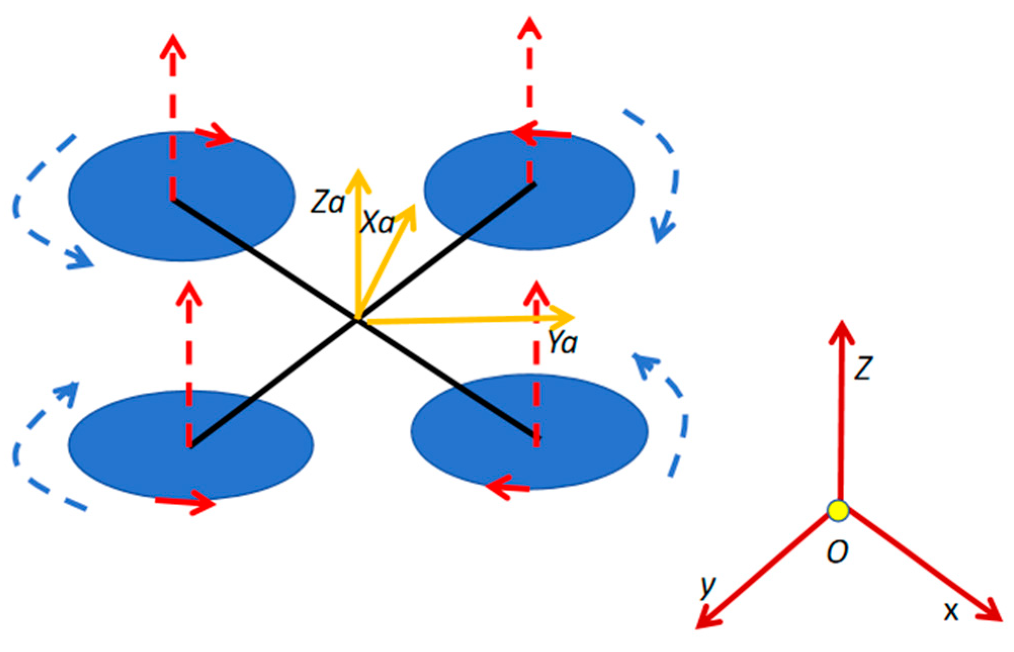
Figure 1) and formulate a dynamic equation, making the following assumptions:
The drone’s center of mass and body origin coincide at one point in the coordinate system.
The drone’s mass is uniformly distributed, with perfect structural symmetry, excluding elastic variations.
Gyroscopic effects and friction forces acting on the drone’s body are ignored.
The Earth’s curvature is disregarded, and a flat Earth surface is assumed to simplify the model.
Given the strong coupling and underactuated nature of UAVs, modeling necessitates the initial determination of coordinate systems, including both the body and geographic coordinate systems.
In
Figure 1, the geographical coordinate system is denoted by red lines, while the body coordinate system is represented by yellow lines. Within the body coordinate system, the three axes are labeled Xa, Ya, and Za. The system’s origin is positioned at the center of gravity of the body, with the Xa axis aligned parallel to the body and oriented in the direction of the body’s motion in the positive direction. The Za axis is perpendicular to the Xa axis and directed upwards, ensuring that the thrust component F1 along the Za axis is naturally positive, opposing the direction of gravitational force g. This configuration allows the control algorithm to directly compare thrust and gravity since both forces have components in the same direction within the body’s coordinate system. Thus, situated within the body’s vertical plane of symmetry, the Ya axis is perpendicular to the OXaZa plane.
The inertial frame (I) is defined as the geographical coordinate system with the Earth’s center as its origin point. The positive direction of the X-axis points eastward from the origin, while the Y-axis points northward. The Z-axis is perpendicular to the OXY plane, extending towards the sky.
2.3. The Establishment of the Model Equation
Firstly, we create a mathematical model of the six degrees of freedom and use them to design the controller for the inner and outer loops:
In order to model the dynamics of the quadrotor UAV, we first consider its six degrees of freedom. These degrees of freedom describe all the possible motions of the UAV in space: three translational motions (vertical lift, lateral side-to-side movement, and forward–backward translation) and three rotational motions (rotation around three main axes, i.e., roll, pitch, and yaw). These six degrees of freedom correspond to the six output variables of the UAV state, which are as follows:
x, y, z: These are the coordinates of the position in the ground coordinate system.
ϕ, θ, ψ: These correspond to the roll, pitch, and yaw angles of the UAV, respectively.
The input variable is the total lift generated by the four rotor blades F1 and three moments around the body spindle F2, F3, F4. Now, we use the constant of proportionality KT to represent the thrust–rotor speed (W) relationship and KM to express the relationship between torque and speed. The moments of inertia are represented by Jx, Jy, and Jz expression, and the distance from the motor to the center of the body is denoted by d.
Next, we establish the rotation matrix as the transformation matrix equation between two coordinate systems. The conversion from the geographic coordinate system to the body coordinate system V (vehicle frame) can be accomplished through rotation about the yaw angle. The transformation involving yaw α, pitch β, and roll γ can be represented by transformation matrix A [
34] as follows:
Next, we utilize Newton’s second law to formulate the linear dynamic equations [
35,
36], obtaining the acceleration components in each direction.
Here, T represents the lift force, and M is the mass of the drone.
Then, by applying Newton’s second law and transforming it through rotation matrix A, we obtain the linear velocity equations [
36,
37]. The components of speed in the ground coordinate system are as follows:
˙represent the speed along the X, Y, and Z axes of the ground coordinate system, respectively. Ultimately, these speed components will be used to update the drone’s velocity and position within the ground coordinate system.
Next, we represent the drone’s angular dynamics using the Euler equations of motion [
38]:
Here, represent the angular velocities around the X, Y, and Z axes, respectively. Since the equations obtained above are nonlinear and interdependent, numerical methods such as the Euler method or the Runge–Kutta method can be used to approximate the integration of these equations at each time step Δt.
We choose the Euler method for numerical integration.
Here γn, βn, and αn are the angular velocities at the current time step, while γn+1, βn+1, and αn+1 are the angular velocities at the next time step. This process is repeated throughout the simulation time, resulting in a time series of angular velocities.
Finally, we establish a nonlinear dynamic model [
39,
40]. Since the state equations describe all the dynamic behaviors of the drone, including linear dynamics (position and velocity) and angular dynamics (attitude and angular velocity), by combining the previous equations, we obtain the linear state equations and angular dynamic state equations.
Based on Newton’s laws of mechanics and the laws of rotational dynamics, we can construct a mathematical model describing the motion of a quadrotor drone:
In the equation of linear velocity (Equation (6)), represent the rate of change of the position vector (X, Y, Z) in the ground coordinate system; Φ, θ, and ψ are Euler angles, representing roll, pitch, and yaw, respectively; F1 is the total lift produced by the rotors; M is the mass of the quadrotor drone; and G is the acceleration due to gravity.
For the equation of angular velocity (Equation (7)), ˙α˙, ˙β˙, and ˙γ˙ represent the rate of change of the yaw, pitch, and roll angular velocities, respectively; Jx, Jy, and Jz are the moments of inertia about the body’s X, Y, and Z axes, respectively; d is the distance from the motor to the body center; and F2, F3, and F4 are the distances from the motor to the body center.
2.4. Parameter Determination
In the process of deduction and refinement for learning, significant experimentation is required to ascertain the values of the model parameters. Given that the control system demands lower resources at this stage, the choice of fuzzy logic for the control system is deemed reasonable. Notably, the thrust function determined through this experimental mechanism aligns more closely with a cubic function derived from parabolic trajectory analyses. The parameters extracted from this identification process are as follows:
Below is how each parameter is obtained and their role in computations and the program:
The way M is obtained is “Measured using a scale”. In the dynamic model in MATLAB, mass plays a vital role in calculating the thrust required for lift and maneuvering through the thrust equation. It directly affects the calculation of acceleration in translational motion equations and impacts the controller’s compensation for gravity.
L is derived from measurements of the physical UAV. It is crucial in the controller’s calculation of torques generated by the motors, which decides the quadrotor’s rotation and stability. It is used to calculate the moments for pitch, roll, and yaw adjustments in the rotational dynamics equations.
J_x, J_y, J_z are obtained using bifilar pendulum tests. These parameters are used to determine the angular accelerations in the simulation’s Euler equations of motion. They are critical for accurately modeling the UAV’s rotational dynamics and for the PID controller to stabilize angular motions.
D is measured from the UAV’s structure. It impacts the calculation of moments and thus the control inputs needed for attitude control. It is used in torque calculations where longer lever arms equate to greater turning forces for the same amount of motor torque.
KT is determined through thrust tests with a dynamometer. It allows the conversion of motor RPM into physical thrust values in the simulation model, which is used by the optimization algorithm to adjust the PID gains for precise altitude control.
KM, similar to KT, is discovered through motion testing. It helps in adjusting motor control inputs within the whale optimization algorithm to fine-tune the PID controller’s performance.
G is the acceleration due to gravity. It is a fixed input in the control system equations, factored into the lift force calculations to maintain the UAV in the air and to correct for the gravitational pull during flight maneuvers.
K_D is experimentally determined through computational fluid dynamics simulations. It is integrated into the dynamic model to account for the resistance experienced by the rotating parts, affecting the UAV’s energy efficiency and the PID controller’s response to rotational commands.
B_a is obtained through empirical testing, measuring the resistance to rotation at different speeds. It is included in the simulation to ensure that the controller compensates for these frictional forces when maintaining stable flight or when changing directions.
K_t is obtained from motor testing; this constant is essential for the control algorithms that manage motor speed. It is used to accurately translate control inputs into motor torques, which is crucial for maintaining desired thrust levels and for maneuvering the UAV.
K_v is also obtained from motor testing; the k_v value is used in the motor control subsystem of the UAV’s simulation model. It helps the optimization algorithm to understand the relationship between voltage and the resulting motor speed, thus enabling precise speed control for stable flight.
L_a is usually measured in an electrical way, and it is used in the electrical modeling of the motor in the UAV control system to determine the current consumption and the phase difference between voltage and current. This affects the PID controller’s ability to accurately adjust the motor speed in a variety of operations.
I_g is directly measured using a bifilar pendulum setup; it is crucial in the control system for predicting the response of the rotors to the control inputs. It affects the dynamics of how quickly a rotor can accelerate or decelerate, which in turn influences the UAV’s agility and stability.
R_a is measured using electrical instruments. It plays a role in efficiency calculations.
γ_2 is derived by fitting empirical thrust data to a polynomial model; this coefficient refines the thrust model by accounting for nonlinearities in thrust force generation. The simulation allows for more accurate prediction and control of the UAV’s vertical acceleration and deceleration, which is crucial for tasks such as landing or avoiding obstacles.
γ_3 is also derived by fitting empirical thrust data to a polynomial model; like γ_2, this higher-order coefficient provides even finer control over thrust force modeling. It is used by the controller to ensure an accurate representation of the UAV’s lift dynamics, especially under different loads and speed changes.
Next, we propose a control strategy based on the ground coordinate system position vectors (
,
,
) along with the rates of change of the roll, pitch, and yaw angular velocities (˙α˙, ˙β˙, ˙γ˙). The designed controller [
41] regulates the rate of change of the position vector through an outer loop, while the inner loop targets the angular velocities of yaw, pitch, and roll. The input to the controller is based on the difference between the actual and desired values, with the output being the corresponding control quantity required to achieve precise control. Next, we will detail the design process of the controller, including the selection and optimization of parameters. The controller uses the deviation between actual and target values as the input to generate appropriate control signals as outputs, enabling precise adjustment of the system.
3. Structure of the Control System
3.1. Design of Control System
We developed a fuzzy PID controller design method based on the whale optimization algorithm, tailored to the nonlinear kinematic characteristics of quadrotor UAVs. Our approach includes a cascaded control architecture, where the inner loop is responsible for attitude control—specifically the angles of roll (ϕ), pitch (θ), and yaw (ψ)—while the outer loop manages position control, targeting displacement at the x, y, and z coordinates. The control system uses the difference between the desired and actual positions as the input for the outer loop controller, which then calculates the necessary lift. Simultaneously, the desired angles output by the outer loop and the actual angles from the inner loop are used to compute angular errors. These errors serve as inputs for the inner loop controller, which then determines the input torques required to maneuver the quadrotor drone. This integrated approach enables the comprehensive management of the drone’s six degrees of freedom, including both orientation and displacement. In the subsequent sections, we will elucidate the application of different controllers in the inner and outer loops and elaborate on the results of these implementations.
Figure 2 illustrates the configuration of the control system.
Figure 2 shows M, l, J_x, J_y, J_z, d, KT, KM, G, γ_2, γ_3. These parameters are defined in
Table 1, representing the mass of the quadcopter UAV, the distance from each rotor to the center of gravity, the moment of inertia around the X-axis, the moment of inertia around the Y-axis, the moment of inertia around the Z-axis, the distance from the motor to the center of the body, the thrust constant of the rotor, the torque constant of the rotor, the gravitational acceleration, and the second- and third-order thrust coefficients. Kp, Ki, and Kd represent the proportional, integral, and derivative gain of the PID controller, respectively. Ee could represent the external error or environmental error that affects the attitude and position of the UAV. E generally stands for the error signal, which is the difference between the desired attitude (or position) and the actual attitude (or position). This error signal is often the input to the control system.
denotes the derivative of the error over time, which reflects the rate of change of the error. It is a term often used in PID (Proportional–Integral–Derivative) control systems, where it contributes to the D-component, providing a prediction of future errors based on the current rate of change.
The diagram outlines a control system for a quadrotor UAV that achieves precise control and robustness to interference by integrating error feedback into real-time adjustments, ensuring that the UAV can effectively respond to changes in its environment and maintain its intended flight path.
3.2. Design of Fuzzy PID Controller
In this part, we detail the adaptive tuning method of the PID controller, which uses fuzzy PID to autotune the parameters and optimizes the command response ability of the controller through the incremental PID strategy. The output of the controller is generated using the following formula:
Here, Kp, Ki, and Kd denote the proportional gain, integral gain, and differential gain, respectively, and are modulated in the following proportions.
In this equation, u(t) denotes the control drive; e(t) is the error signal; Kp0, Ki0, and Kd0 represent the basic gain of the PID controller; and δKp, δKi, and δKd are adjusted according to the requirements. This adaptive approach enables the controller to adapt to fluctuations in system dynamics and external disturbances, maintaining stability and performance efficiency.
In this study, a control method combining fuzzy PID control and the whale optimization algorithm is adopted, and its structure is shown in
Figure 3. The chaotic whale can adjust the δKp, δKi, and δKd of the PID controller, and then, the controller can control the controlled object. We conclude that combining chaotic mapping, the whale algorithm, the fuzzy rule, and PID control has a good control effect.
The design of the fuzzy control rules in this study is described in
Table 2.
In the fuzzy control presented in this article, there are typically two inputs: the error (E) and the rate of change of the error (EC), along with one output, which is the gain of the control signal.
Table 2 encompasses a set of rules for three fuzzy controllers, targeting the proportional gain (Kp), integral gain (Ki), and differential gain (Kd). Each cell’s values, such as PB, PM, ZO, NS, NM, and NB, represent the linguistic variables of the fuzzy sets, corresponding to distinct fuzzy logic rules.
The significance of each fuzzy logic rule is as follows:
NB (Negative Big): A significant negative number, indicating a large and negative error or a large and negative rate of change of error.
NM (Negative Medium): A medium negative number, implying a moderate and negative error or a moderate and negative rate of change of error.
NS (Negative Small): A small negative number, suggesting a small and negative error or a small and negative rate of change of error.
ZO (Zero): Zero, meaning the error is near zero, or the rate of change of error is near zero.
PS (Positive Small): A small positive number, signifying a small and positive error or a small and positive rate of change of error.
PM (Positive Medium): A medium positive number, denoting a moderate and positive error or a moderate and positive rate of change of error.
PB (Positive Big): A significant positive number, indicating a large and positive error or a large and positive rate of change of error.
For instance, if the error (E) is a large positive number (PB), and the rate of change of error (EC) is also a large positive number (PB), then the proportional gain (Kp) might be set to a medium negative number (NM), meaning the controller may reduce the output to attempt to minimize this large positive error.
3.3. Whale Algorithm-Optimized Fuzzy Control Rules
In the design of a fuzzy PID controller based on the whale optimization algorithm (WOA), the number of control rules increases significantly due to the complexity of the seven fuzzy state variables and the dual-input–triple-output system. Specifically, with a fuzzy logic approach, the number of control rules alone can be in the hundreds. Determining these rules often relies on the experience and knowledge of experts and can be a daunting task. To solve this problem, a whale optimization algorithm is introduced in this study to optimize the rule set in the fuzzy controller.
Given that the ITAE (Integral of Time-weighted Absolute Error) takes into account the product of the absolute error and time, it emphasizes the system’s performance in the presence of long-standing errors in contrast to other performance metrics, such as Mean Absolute Error (MAE) or Mean Squared Error (MSE). This emphasis is due to ITAE’s calculation where the longer the error persists, the greater its impact on the overall performance metric. This weighting method effectively penalizes large errors persisting over time, encouraging the control system to reduce errors more rapidly and achieve a steady state quickly. Moreover, ITAE reduces reliance on expert experience, making the optimization process more objective and reliable. In multi-input multi-output systems, each output directly affects performance, and ITAE allows for a balanced consideration of the long-term performance of each output, thereby finding an optimized overall solution in complex control systems. In short, ITAE provides an effective means of balancing long-term performance and rapid system responsiveness. In this study, when designing the fuzzy PID controller using the Chaotic Mapping Whale Optimization Algorithm (WOA), considering the potential high complexity and the potentially large number of control rules, utilizing ITAE as the performance criterion simplifies the controller design. It quantifies the control system’s response to errors over time and provides a clear objective function, enabling the whale optimization algorithm to explicitly pursue a control strategy that reduces long-term errors throughout the optimization process.
Therefore, in this study, we use integration time multiplied by the absolute error (ITAE) as a performance criterion to evaluate the optimization process. This criterion is achieved by calculating the time integration of the error of the control quantities X1 and X2. In the whale optimization algorithm, the fitness function is defined as , where H(t) denotes the control error. The goal of optimization is to maximize this fitness function, which means that the larger the value of the fitness function, the better the control performance achieved.
3.4. Whale Algorithm
3.4.1. Conventional Whale Optimization Algorithm
The traditional whale optimization algorithm (WOA) is a biomimetic optimization algorithm proposed by Mirjalili and Lewis in 2016 [
42] to mimic the social behavior and hunting mechanisms of humpback whales. It has been applied in various fields, including in control systems such as fuzzy PID (proportional–integral–derivative) controllers for stabilizing quadcopter UAVs. In this case, the WOA can optimize the parameters of the PID controller to improve performance and stability.
The algorithm functions by simulating the bubble-net hunting strategy of humpback whales, which is described below.
Encircling prey: Whales locate and encircle their prey before starting the bubble-net feeding method. Mathematically, this behavior is modeled as
In this equation, is the position vector of the target, which is the best solution found so far, is the whale’s position vector, and are coefficients that help determine the nature of the whale’s movement toward the prey or target, t is the current iteration, and is the calculated distance vector between the whale’s position and the target’s position.
Bubble-net attacking method (exploitation phase): This phase includes two approaches: shrinking encirclement and spiral position update.
Shrinking encirclement mechanism: This is achieved by decreasing the value of in the equation.
Spiral position update: The spiral equation between the whale and the prey (optimal solution) is defined as
In the scenario described above, is the distance between the whale and its prey. The constant b is used to define the spiral shape, and l is a random number within the range of [−1, 1].
Searching for prey (exploration phase): To simulate the random search for prey, the WOA utilizes the vector , where the position of the search agents is updated when , allowing the whales to search outside the region of the current best solution. This mechanism ensures global optimization capability and exploration of the search space.
Parameter adaptation: The algorithm adaptively adjusts the parameters throughout the optimization process to balance exploration and exploitation, ensuring that the algorithm converges to the global optimum.
In the context of quadcopter control, the WOA is generally used to optimize the PID control parameters (Kp, Ki, and Kd) to achieve the desired performance criteria, such as minimum overshoot, settling time, and steady-state errors. The optimization process is as follows:
Define the cost function based on the dynamic response characteristics of the quadcopter.
Initialize the population of the candidate solution (whales) using random PID parameters.
Iteratively apply the WOA step to adjust the PID parameters to the optimal set of minimized cost functions.
This approach makes it possible to design a quadcopter control system that adaptively responds to changes in dynamics and external disturbances, thereby enhancing stability and maneuverability.
3.4.2. Chaotic Mapping-Optimized Whale Algorithm
The chaos mapping-enhanced whale optimization algorithm represents a simple method for tuning the PID controller, which is essential for achieving the expected dynamic response in the control system. Its rationale relies on the use of complex models of chaos theory to diversify the initial population of potential solutions, enabling a more thorough exploration of the solution space. The enhanced mathematical foundation is built on top of the application of logic mapping, expressed as . When the parameter value is within a certain range, it becomes more refined due to its chaotic behavior. By merging chaotic sequences, the algorithm is unlikely to succumb to the local optimal trap, which is a common drawback of traditional time-loss methods. This results in a more robust and reliable PID controller, as the optimization process explores all possible parameter settings, ensuring the responsiveness and stability of the control system.
In practice, the chaotic WOA first generates initial populations using chaotic sequences [
43] to ensure good distribution in the latent solution space. Each individual in the population represents a set of PID parameters. The algorithm then iteratively updates each individual’s position in the population using the original WOA equation and chaotic sequences to navigate to the optimal PID parameter set. This process involves evaluating the performance of each group using a predefined cost function that reflects the expected outcomes of the control system, such as minimal overshoot, fast settling time, and low steady-state error.
The use of chaotic mapping to initialize the whale optimization algorithm (WOA) has several advantages over the traditional WOA. Due to its inherent irregularity and stochasticity, chaotic mapping can more uniformly cover the search space, avoiding the convergence of candidate solutions to local optima. This results in a more diverse initial population, which enhances the global search capability and could more rapidly converge to the global optimum. Thus, incorporating chaotic mapping into the WOA can enhance the algorithm’s ability to escape from local minima, enable a more thorough exploration of the solution space, and help solve complex optimization problems such as tuning PID controllers.
Therefore, we integrate chaotic mapping into the optimization process, aiming to enhance the performance and reliability of the PID controller by boosting global search capabilities and preventing premature convergence.


