

Rapid Prototyping of Anomalous Reflective Metasurfaces Using Spray-Coated Liquid Metal
by
 , , and
Glan Allan V. Manio
*,†,
Matthew T. Kouchi
†,
Saige J. Dacuycuy
†,
Aaron T. Ohta
 and
and
Wayne A. Shiroma
* Department of Electrical and Computer Engineering, University of Hawai’i at Mānoa, Honolulu, HI 96822, USA
*
Authors to whom correspondence should be addressed.
†
These authors contributed equally to this work.
Materials 2024, 17(9), 2003; https://0-doi-org.brum.beds.ac.uk/10.3390/ma17092003
Submission received: 20 March 2024
/
Revised: 20 April 2024
/
Accepted: 22 April 2024
/
Published: 25 April 2024
(This article belongs to the Special Issue Liquid Metals: From Fundamentals to Applications)
Abstract
:Reconfigurable intelligent surfaces (RISs) have the potential to improve wireless communication links by dynamically redirecting signals to dead spots. Although a reconfigurable surface is best suited for environments in which the reflected signal must be dynamically steered, there are cases where a static, non-reconfigurable anomalous reflective metasurface can suffice. In this work, spray-coated liquid metal is used to rapidly prototype an anomalous reflective metasurface. Using a pressurized air gun and a plastic thin-film mask, a metasurface consisting of a 6 × 4 array of Galinstan liquid–metal elements is sprayed within minutes. The metasurface produces a reflected wave at an angle of 28° from normal in response to a normal incident 3.5-GHz electromagnetic plane wave. The spray-coated liquid–metal metasurface shows comparable results to an anomalous reflective metasurface with copper elements of the same dimensions, demonstrating that this liquid–metal fabrication process is a viable solution for the rapid prototyping of anomalous reflective metasurfaces.
1. Introduction
Reconfigurable intelligent surfaces (RISs) promise to improve coverage for signals negatively impacted by obstructions present in the line-of-sight (LOS) path, making them an attractive technology for 5G and beyond mobile communications [1]. A typical RIS combines passive reflective elements with active devices such as varactors [2,3,4,5] or PIN diodes [6,7,8,9], while others use phase-tunable materials such as liquid crystals [10,11,12], 2D materials [13,14,15,16,17], or phase-change materials [18,19]. Creating a tunable reflection phase gradient across a surface enables the RIS to dynamically redirect an incoming signal to an anomalous direction not predicted by Snell’s Law.
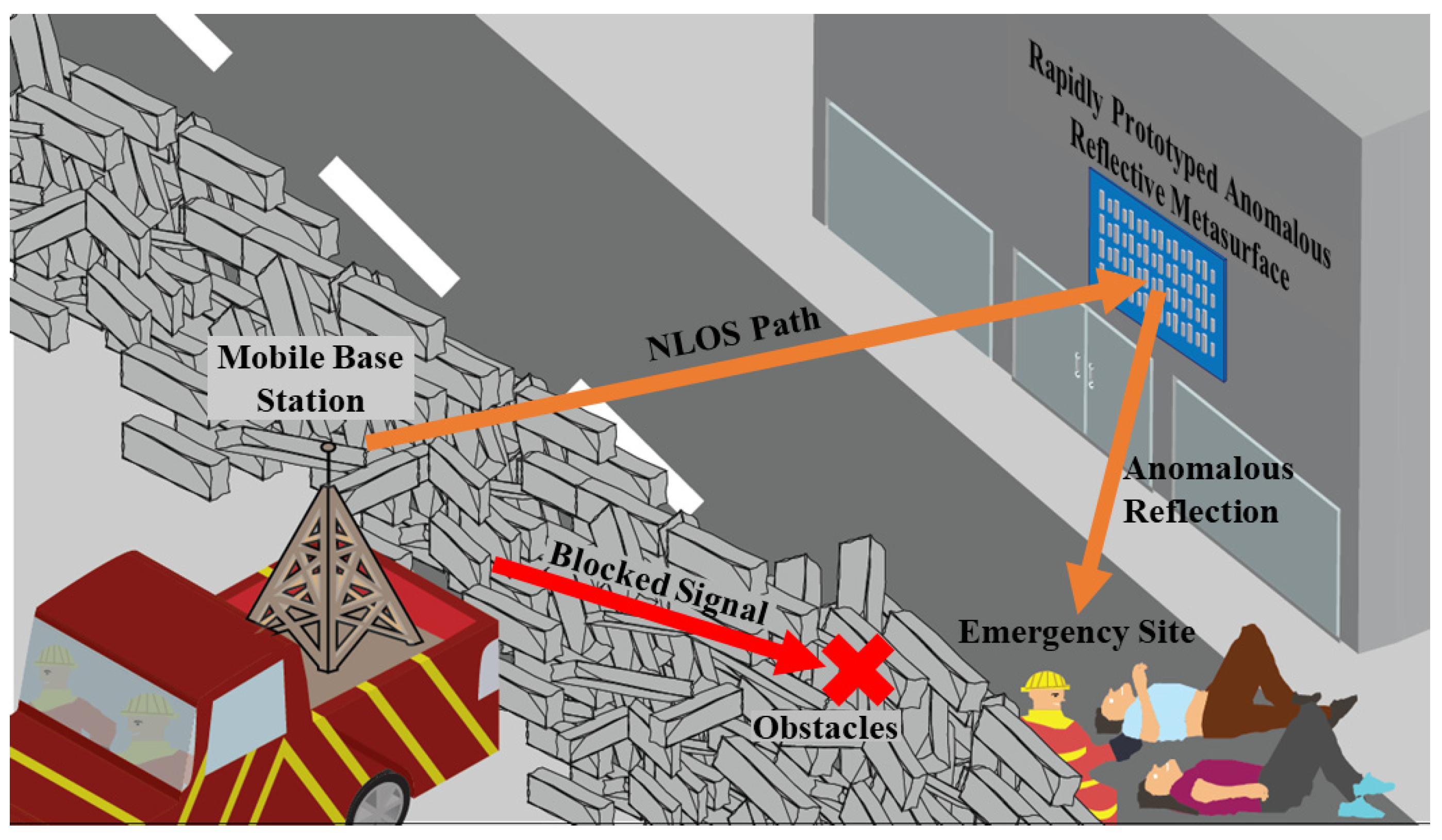
In some use cases, however, an RIS may require little to no reconfiguration of the reflected signal [20]. For example, in the aftermath of a natural disaster, a rapid-response network can be set up, as shown in Figure 1. Here, a mobile base station is deployed to an emergency worksite, but obstacles block a LOS link from being established to emergency workers aiding survivors. Under such conditions, where the emergency workers are relatively stationary for hours at a time, a static anomalous reflective surface with little to no reconfigurability is sufficient. The reflective metasurface can be rapidly prototyped and positioned to provide an anomalous-angle non-line-of-sight (NLOS) link to the emergency workers. If the emergency workers subsequently move to a different site, say to the top left of Figure 1, another rapidly prototyped metasurface can be quickly fabricated using a different template that provides the appropriate anomalous reflection angle.
Although a static anomalous reflective metasurface is limited to a fixed reflection angle, it is simpler and less expensive than an RIS with active elements. Metasurface geometries have previously been created with copper elements using etching, milling, or placing copper tape on an unclad substrate [21]. Other metasurfaces have been explored using sputter deposition [22], inkjet printing [23], screen printing [24,25], and 3D printing to create reflective elements [26]. Although these fabrication methods are effective, spray-coated liquid metal for rapid prototyping has numerous advantages compared to traditional fabrication methods. The main components that differentiate our proposed method are portability, simplicity, and scalability. Compared to methods such as copper milling/etching, 3D printing, and inkjet printing, spray-coating provides a faster fabrication time with less expensive equipment. The proposed method also has a simple fabrication process, only requiring the creation of a mask and spray-coating the liquid metal onto a substrate. Once the mask is created, spray-coating of liquid metal has a faster scalability implementation, where the mask can be moved to new locations for the addition of reflective elements. Therefore, an alternative rapid prototyping method utilizing spray printing of liquid–metal metasurface elements is investigated.
The liquid metal used here is Galinstan (Rotometals Incorporated, San Leandro, CA, USA), a near eutectic gallium-based alloy consisting of Ga 68.5 wt%, In 21.5 wt%, Sn 10 wt%. Galinstan, with this composition, has a melting temperature of 11 °C [27]. Due to the adhesiveness of Galinstan occurring from the oxide skin produced by the spray deposition, electrolytes such as sodium hydroxide (NaOH) can be used to remove Galinstan after use and preserve the substrate material for reusability [28,29]. Galinstan also has a high electrical conductivity of 3.46 × 10⁶ S/m [30], making it an attractive metal for the aerosol spray deposition of conductive films [31,32].
Although spray deposition using conductive paint has been previously demonstrated for transmissive metasurfaces [33], this paper reports the first rapidly prototyped aerosol spray deposited liquid–metal anomalous reflective metasurface. Using a pressurized air gun and a plastic thin-film mask, liquid metal is patterned on a substrate, with an array of liquid–metal elements capable of being sprayed within minutes. Successful tests were conducted, demonstrating the viability of anomalous reflective metasurfaces fabricated using the rapid prototyping method.
2. Materials and Methods
One of the defining features of an anomalous reflective metasurface is its ability to induce reflections at an angle that is not predicted by the conventional Snell’s Law. This is made possible by engineering a phase gradient on the surface between two media, which, in turn, is generated by periodically arranging unit cells with varying geometries across the surface [34]. To quickly apply these geometries to a surface, spray deposition of liquid metal is utilized.
2.1. Unit Cell Design
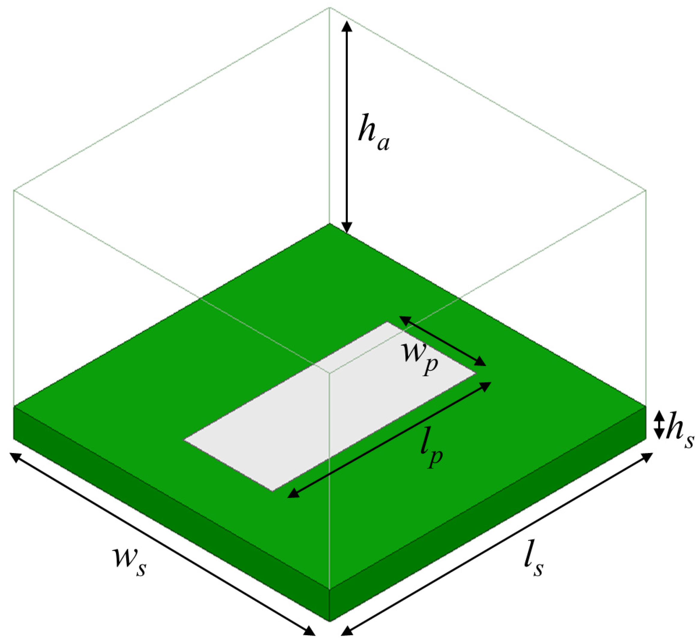
Figure 2 shows the metasurface unit cell, which consisted of a rectangular Galinstan element (length lp, width wp, height hp) on a Rogers RT/duroid 5880 substrate (hs = 3.175 mm, εr = 2.2, tan δ = 0.0009) (Rogers Corporation, Chandler, AZ, USA). This substrate was specifically selected because of its low-loss characteristics to enhance the reflective metasurface efficiency. A 35.6-μm-thick copper backplane was positioned beneath the substrate. The unit cell dimensions (length ls, width ws) largely set the operating frequency of 3.5 GHz.
The unit cell was designed in Ansys HFSS, using a Floquet-port simulation to mimic a normally incident uniform electromagnetic plane wave source on an infinite array of these unit cells. The air-box height ha was set to λ0/4, although de-embedding was enabled to simulate the reflection coefficient S11 at the surface. The key to designing an anomalous reflective metasurface is to vary the geometry within a given unit cell—thereby resulting in a distinct S11 state—and then positioning different unit cell states in a quasi-periodic pattern that yields a phase gradient for the desired anomalous reflection.
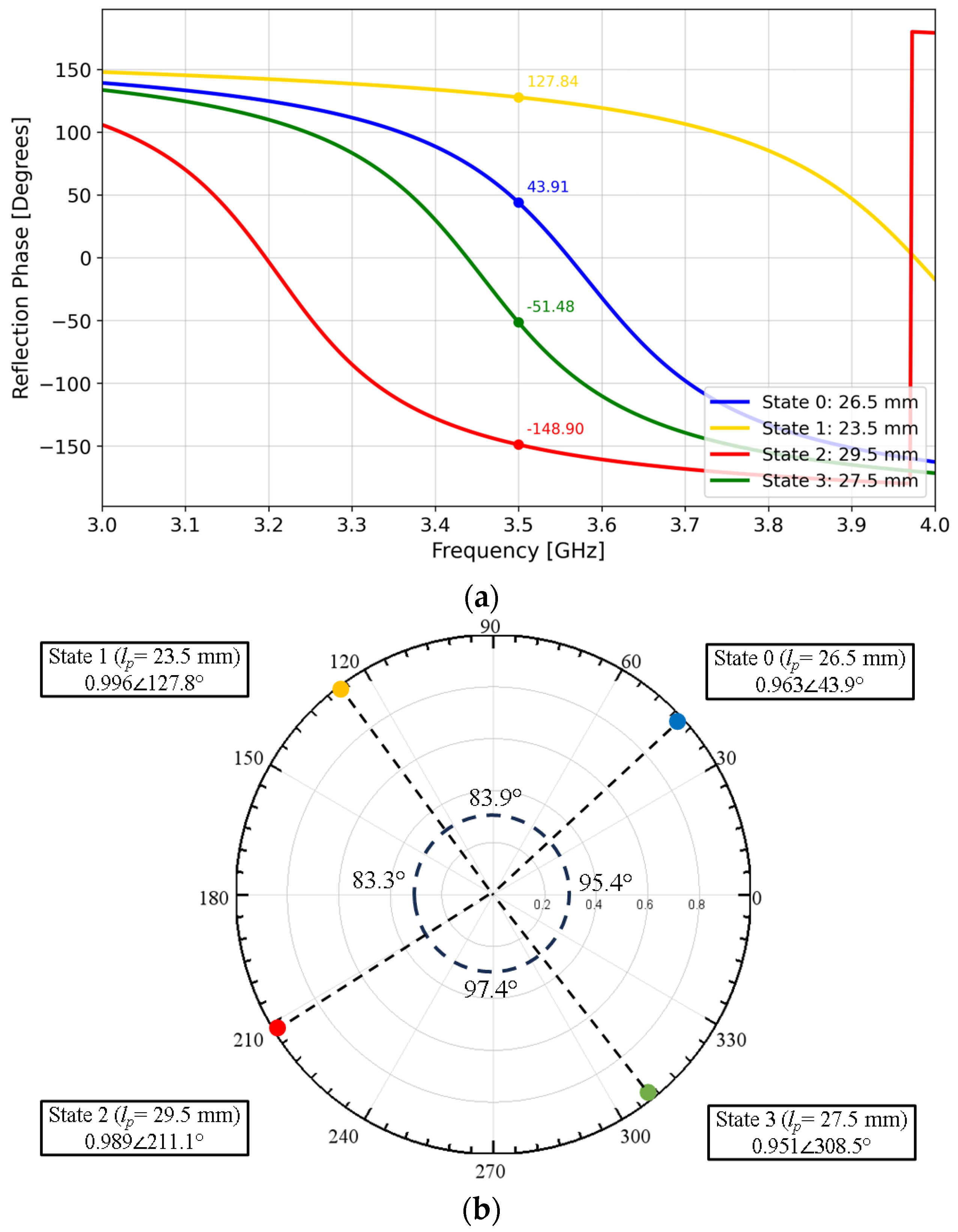
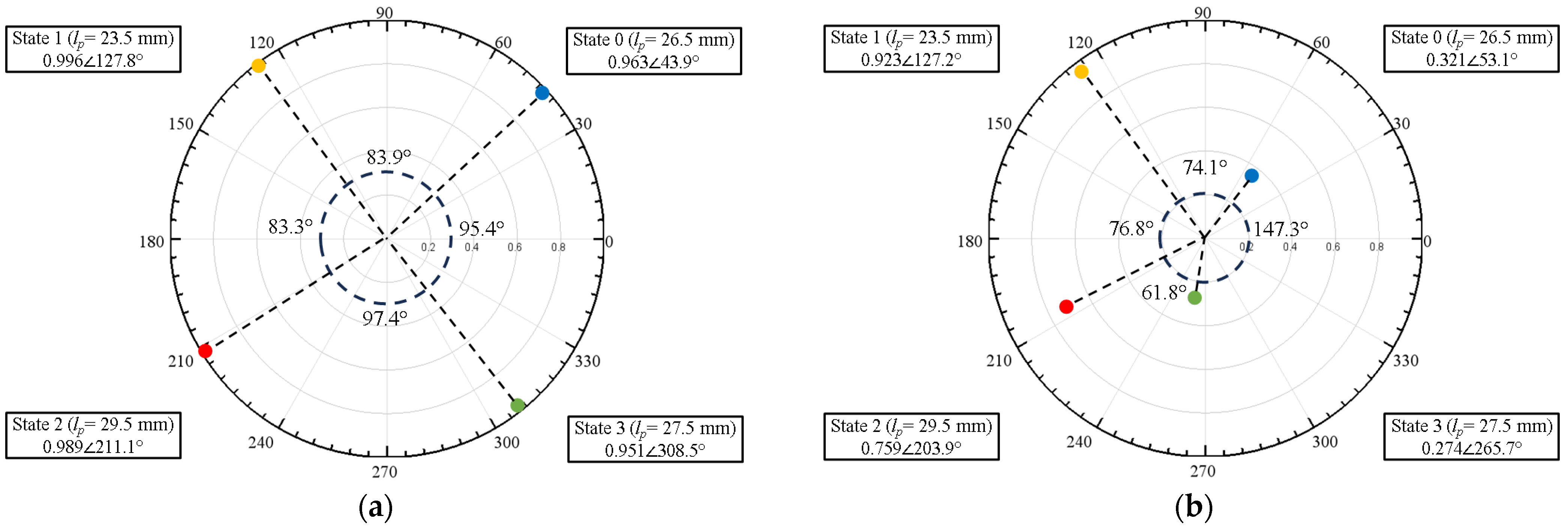
For example, if lp is set to 26.5 mm, a Floquet-port simulation that mimics an infinite array of identical unit cells results in the blue curve of the reflection phase versus frequency response shown in Figure 3a. Repeating the Floquet-port simulation for lp = 23.5, 29.5, and 27.5 mm resulted in three additional curves (yellow, red, green).
In short, varying the patch length lp results in four distinct S11 states that are approximately 90° apart at 3.5 GHz (Figure 3b), hereafter referred to as State 0, 1, 2, and 3. An array consisting of an alternating State 0-1-2-3 periodic pattern of these unit cells then yields a 360° phase gradient in ~90° increments. This phase gradient, in turn, results in anomalous reflection as predicted by the Generalized Snell’s Law of Reflection [35]. Based on a 3.5-GHz operating frequency with a State 0-1-2-3 phase progression pattern, the anomalous reflection angle for normal incidence given by the Generalized Snell’s Law is:
An anomalous reflective metasurface with four unit-cell states ~90° apart is known as 2-bit coding [36], where arranging the unit cells in the State 0-1-2-3 pattern results in a single-beam reflection. Similarly, a metasurface with just two unit-cell states ~180° apart is known as 1-bit coding. A 1-bit metasurface with a State 0-0-2-2 pattern would result in the same reflection angle θr as the State 0-1-2-3 pattern but would also produce a symmetric beam at −θr [37]. Eliminating the symmetric beam to realize a single-beam reflection would require a large oblique angle of incidence [38].
2.2. Array Design
The unit cell results presented above were based on an HFSS Floquet-port simulation, which assumes an infinite array. An HFSS bistatic radar cross-section (RCS) simulation was performed next, again using a periodic State 0-1-2-3 pattern to simulate a finite array.
Figure 4 shows the bistatic RCS of a 16 × 16 element array with a simulated reflected beam at ~36°, in agreement with the Generalized Snell’s Law calculation. Figure 4 also shows that a 6 × 4 element array results in a lower directivity as expected for a smaller array, but the ~28° reflection is still close to that predicted by Generalized Snell’s Law and has the additional advantage of requiring ~10 times fewer elements than a 16 × 16 array. The sections that follow thus focus on the smaller 6 × 4 array.
2.3. Fabrication
A 0.1-mm thick mylar/transparency film was used as a mask for the spray-coating process. The mask was placed on a 229 mm × 152 mm Rogers RT/duroid 5880 substrate, and a Master G233 commercial airbrush (TCP Global Corporation, Las Vegas, NV, USA) was used to spray-coat Galinstan liquid metal, with the airbrush nozzle positioned perpendicular to the substrate surface. To reduce oxidation of the spray-coated liquid metal, the air pressure was set to the lowest setting of 20 psi, and the airbrush nozzle was placed 5 cm from the substrate surface [39]. Each patch was sprayed for less than one second in an up-and-down S-pattern, one element at a time until all patches had an even coating of liquid metal (Figure 6).
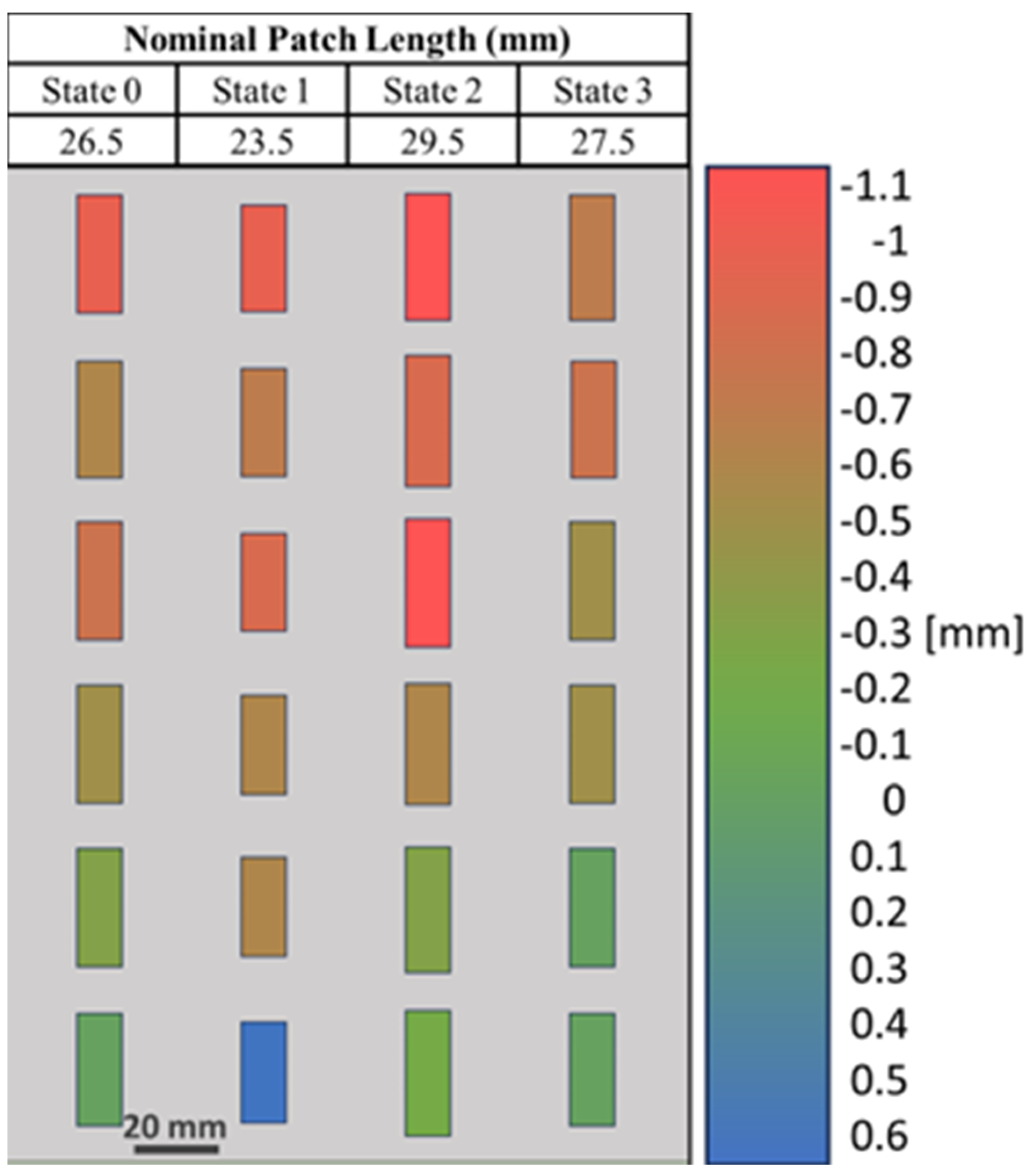
After fabrication, small variations in the lengths of several patches were observed (Figure 7). To investigate further, the dimensions of each of the 24 patches were measured (Figure 8). The average variation in patch length lp was 1.74%, where most of the patches exhibited shorter lengths due to under-spraying. The average variation in the patch width wp was 0.22%, which is negligible (Table S1). A simulation using the as-fabricated lengths of each patch is shown in Figure 9. A detailed explanation comparing these two curves follows in Section 4.
3. Results
3.1. Bistatic RCS Measurements
Figure 10 shows the experimental setup for measuring the metasurface’s bistatic RCS. A 9-dBi-gain transmitter antenna was positioned for normal incidence at the boresight of the Device Under Test (DUT), while a 9-dBi-gain receiver antenna was mounted to a Newport MM3000 1-axis motion controller (Newport Corporation, Irvine, CA, USA) and rotated azimuthally about the metasurface DUT in 2° increments. A Keysight FieldFox N9951B network analyzer (Keysight, Santa Rosa, CA, USA) was connected to both antennas. To accurately measure the performance and avoid multipath interference, the experiment was conducted in a large open area outdoors with the metasurface DUT positioned in the far field of both the Rx and Tx antennas.
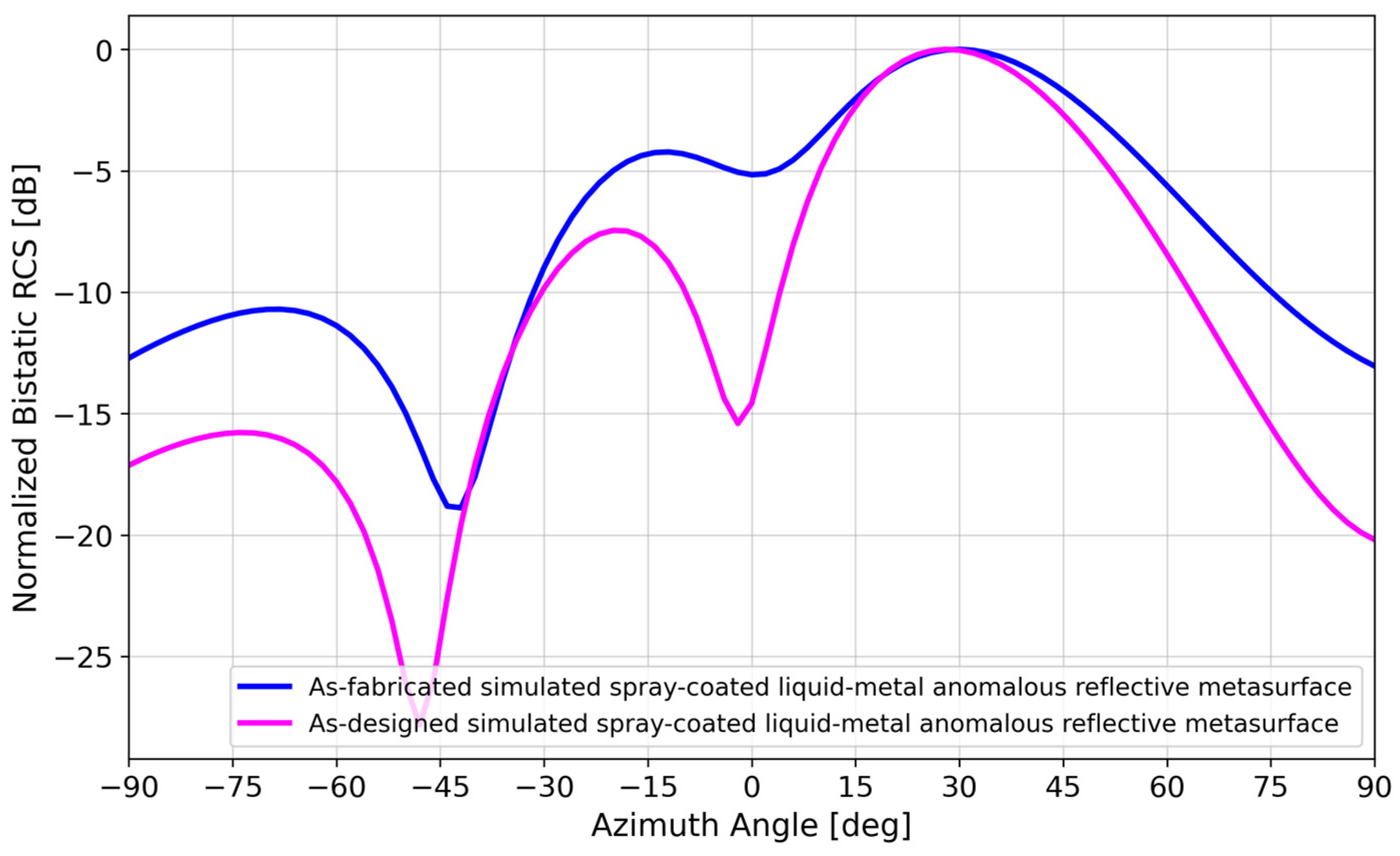
Figure 11 compares the bistatic RCS of the as-fabricated simulated versus measured spray-coated liquid–metal metasurface. There is good agreement, particularly at the ~28° anomalous reflection angle. This agreement is closely maintained for most of the single-beam lobe between 24 and 30°.
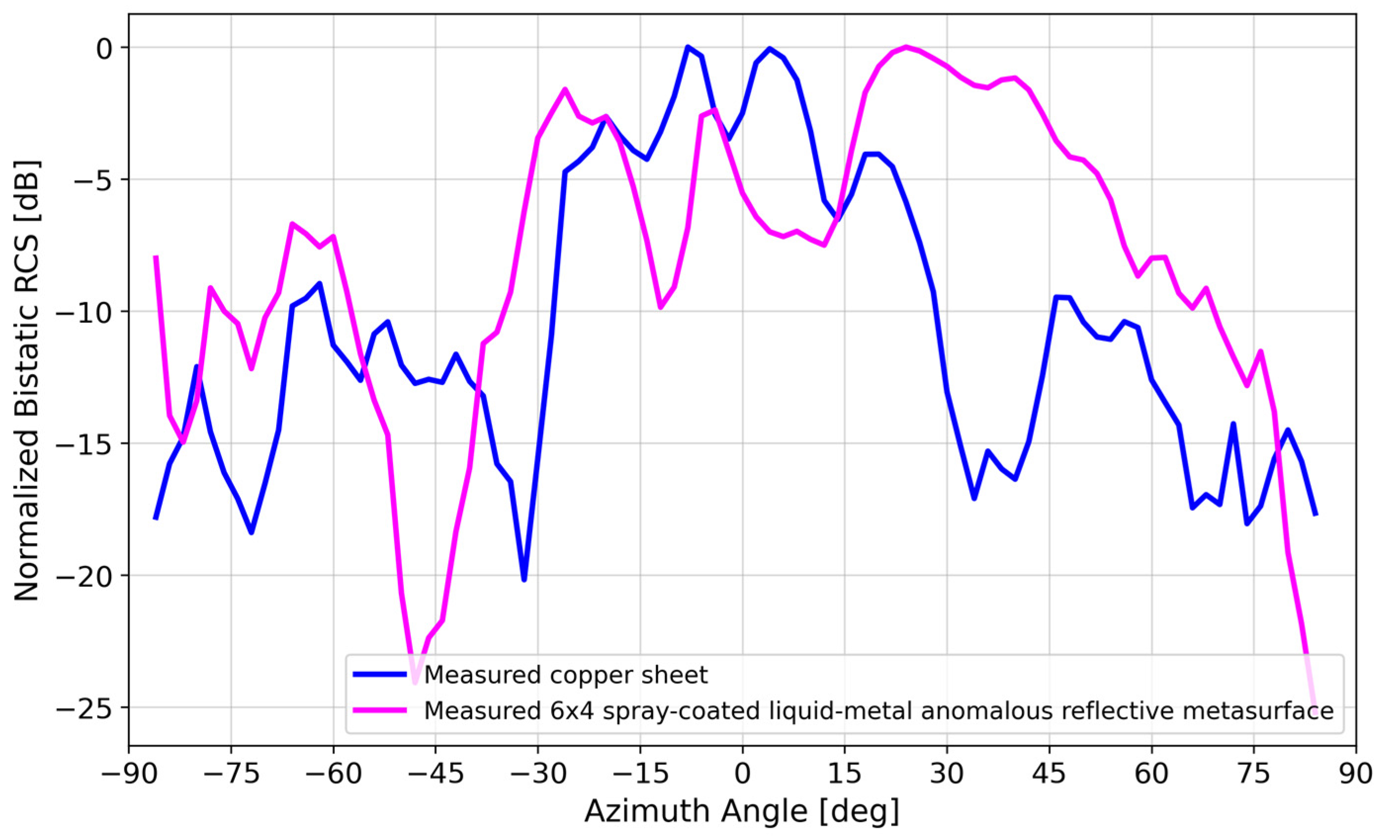
Figure 12 compares the measured bistatic RCS of the spray-coated liquid metal to that of a copper sheet of the same size, replacing the metasurface DUT in Figure 10. At the 28° anomalous reflection angle, the copper sheet reflected ~9 dB less power than the spray-coated liquid–metal reflective metasurface. On average, the spray-coated liquid–metal reflective metasurface performed ~10 dB better than the copper sheet within the 20°–40° anomalous reflection beamwidth.
3.2. Directivity Analysis
Adopting the methodology employed by [40], we compared (1) the maximum directivity of a uniform aperture of the same area as the 6 × 4 metasurface, (2) the simulated maximum directivity of the as-designed and as-fabricated 6 × 4 liquid–metal metasurface from HFSS, and (3) the measured maximum directivity of the fabricated 6 × 4 liquid–metal metasurface. Table 1 summarizes this comparison.
For a perfectly conducting uniform aperture of the same area as the 6 × 4 metasurface (A = 229 mm × 152 mm), the maximum directivity is = 17.7 dBi [41]. For a liquid–metal metasurface occupying the same area, the maximum directivity was 16.4 dBi (as designed) and 13.9 dBi (as-fabricated), according to HFSS simulations (Figure 13).
The measured maximum directivity can be estimated from [41]
where are the half-power beam widths in orthogonal planes. Based on the measured data for the 6 × 4 liquid–metal metasurface in Figure 12, the maximum directivity was estimated to be 13.2 dBi after subtracting 3 dB due to the sizable minor lobe [41].
As seen in Table 1, the measured maximum directivity was 4.5 dB less than that of a comparison perfectly conducting uniform aperture. By comparison, [40] had an 8 dB difference, understandably larger given the significantly higher frequency and design complexity compared to this paper’s passive design.
4. Discussion
Ensuring high array reflectivity (large |S11|) requires adequate conductivity of the liquid–metal patches, which in turn requires minimizing liquid–metal oxidation during the spray-coating process. This section discusses the effect of process variations introduced during the fabrication process—specifically, the effect of liquid–metal patch length variations due to spray-time durations and liquid–metal bulk conductivity variations due to oxidation.
4.1. Effect of Variations in Patch Length
A short spraying duration is desired to reduce liquid–metal oxide formation, which reduces electrical conductivity [39]. However, a shorter spraying duration also increases the chance of under-spraying. Liquid metal may not coat the target surface evenly, resulting in incomplete coverage of some areas and, therefore, uneven patch lengths lp, as previously shown in Figure 7 and Figure 8.
Floquet-port and finite-array simulations were performed in HFSS to study the effect of variations in patch length lp, which affect unit-cell resonances due to inductance and capacitance effects [42], thereby affecting array performance. Figure 14 illustrates the change in S11 if the patch lengths varied ±0.5 mm from their nominal values in Figure 3. It was observed that the effects of lp variations in all four states were not uniform, with State 0 (lp = 26.5 mm) and State 3 (lp = 27.5 mm) having the most potential to introduce error because of the wide phase variability. Figure 15 illustrates the effect of varying the lengths of all State 3 unit cells in a 6 × 4 array by ±0.5 mm from its nominal value of 27.5 mm. It is interesting to note the similarity of Figure 15 to Figure 9, where two lobes appeared instead of the well-defined lobe at 28°. While Figure 9 is a simulation of the array incorporating the as-fabricated shortened patch lengths, which predicts both the anomalous reflecting lobe at 28° as well as an emerging broadside lobe at 0°, Figure 14 provides the insight leading to this behavior: that the shortening of certain states in particular lead to a phase-gradient imbalance.
4.2. Effect of Variations in Liquid–Metal Bulk Conductivity
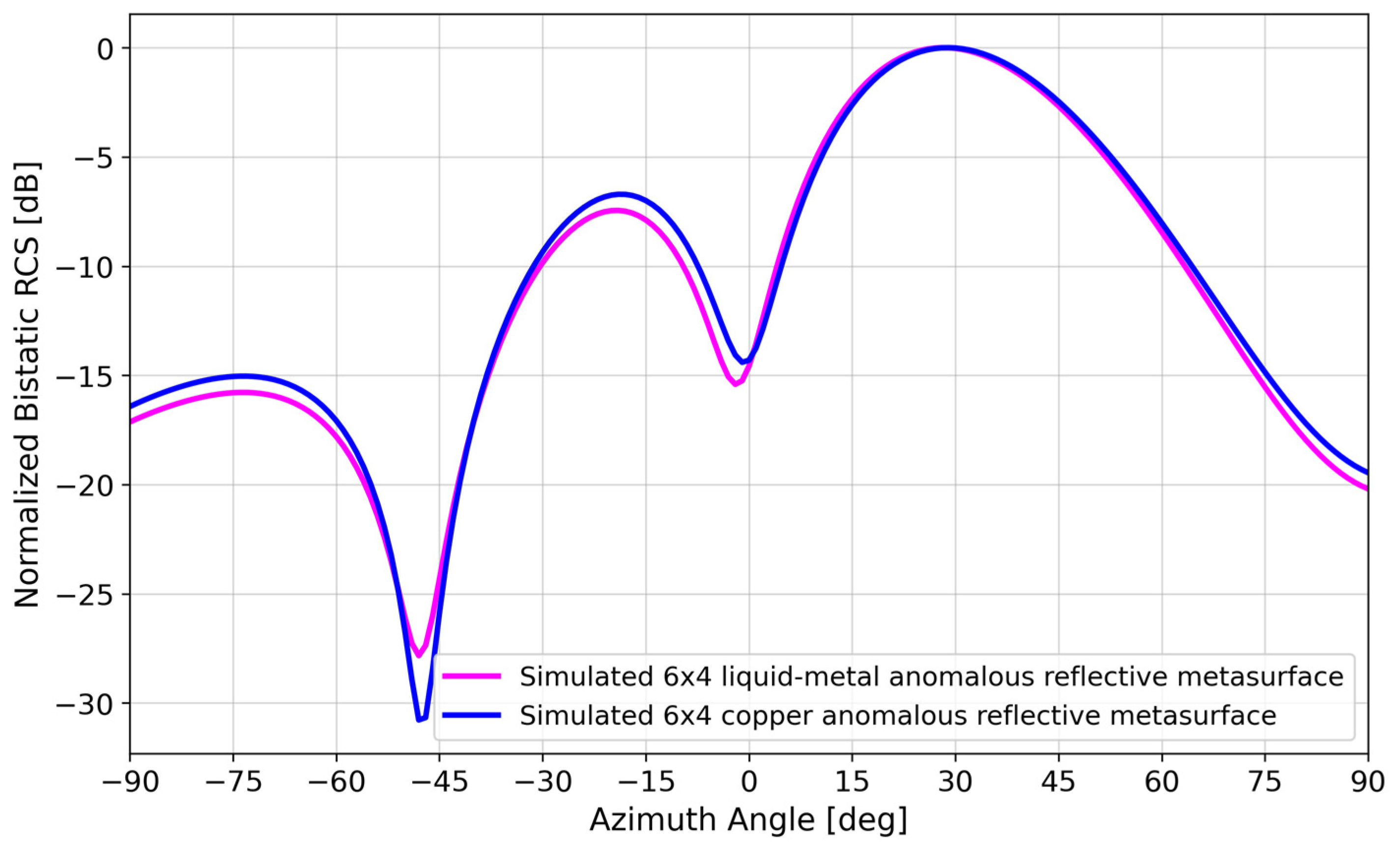
Figure 5 shows that there was a negligible difference in the bistatic RCS simulation of a Galinstan versus copper 6 × 4 array, despite the order-of-magnitude difference in conductivity (3.46 × 10⁶ S/m vs. 5.8 × 10⁷ S/m).
Experimentally, however, we did observe a difference away from the anomalous reflection angle. For comparison purposes, a 6 × 4 copper array (Figure 16) was fabricated with a Silhouette Portrait 3 craft cutter using 0.15-mm-thick copper tape cut to the dimensions indicated in the caption of Figure 2 for the State 0-1-2-3 pattern. The detailed fabrication process is described in [43].
Figure 17 compares the measured bistatic RCS patterns of the copper vs. spray-coated liquid–metal metasurface. Although there was good agreement at the ~28° anomalous reflection angle, the agreement at boresight was not as good, with the spray-coated liquid–metal metasurface mimicking a copper sheet, reflecting ~10 dB more power than the copper array.
Section 4.1 discussed how patch length variations induced by pressure spraying explain some of the undesired boresight reflection effects. In addition, the radiation pattern of the metasurface can also be affected by the bulk conductivity of the reflective elements. Individual element conductivity varied depending on the amount of oxide formed due to the employed spraying parameters. In this section, we discuss liquid–metal bulk conductivity as another factor.
Liquid–metal pressure-spraying with an airbrush is characterized by three main parameters: spraying time, spraying distance, and air pump pressure [39]. In our application, air-pump pressure was constant, but due to the manual spraying procedure, spraying time and distance were variable. The liquid–metal thickness applied during the process was proportional to the spraying time and inversely proportional to the spraying distance. In addition, as the patch thickness increased, its bulk conductivity decreased due to an increased presence of oxide [39]. During longer spraying periods, the oxide layer on the liquid–metal surface was constantly broken, allowing more metal to become exposed to air. Thus, precautions must be taken to reduce the amount of air exposure to the liquid–metal patches, mainly in the form of low pressure and decreased spraying times.
Figure 18 illustrates the change in S11 at 3.5 GHz if the conductivity was reduced from 3.46 × 10⁶ S/m to 1.4 × 10⁴ S/m. The bulk conductivity upper-bound value was taken from [31], while the lower-bound value was from the work presented in [39], in which 1.4 × 10⁴ S/m was the smallest conductivity value measured using similar airbrush spraying parameters as our tests.
The most obvious effect in comparing Figure 18a,b was the |S11| reduction for States 0, 2, and 3, but interestingly, there was not too much of an effect on ∠S11, compared to the effect of patch length on ∠S11 as shown in Figure 14. This is supported by the bistatic RCS pattern of a homogeneously low-conductivity metasurface illustrated in Figure 19, in which the anomalous reflection lobe at 28° was maintained. However, due to the decreased phase gradient between adjacent unit cells, the metasurface approached that of a uniform metal sheet, with more boresight reflection and a reduced side lobe due to the reduced phase gradient along the surface.
Other factors, such as the resulting droplet size of the liquid metal due to the employed spraying parameters and the temperature of the liquid metal, could contribute to the change in bulk conductivity that results in the slight deformation of the radiation pattern in Figure 19. In combination with the effects of the variation on patch length and the amount of oxide due to the spraying parameters, the resulting mismatch between the simulated and fabricated spray-coated liquid–metal anomalous reflective metasurface seen in Figure 11 occurred.
5. Conclusions
This paper presented what is believed to be the first rapidly prototyped anomalous reflective metasurface based on spray-coating of Galinstan liquid metal. As a demonstration, a 6 × 4 element spray-coated liquid–metal metasurface operating at 3.5 GHz demonstrated an anomalous reflection at 28°, similar to a metasurface with copper reflective elements of the same dimensions. Differences between the measured and simulated results of the spray-coated liquid–metal metasurface were attributed to variances in the fabricated patch lengths and the bulk conductivity of the liquid–metal films. Therefore, future works could be geared toward fabrication process improvements.
Manual spray-coating was used to fabricate the liquid–metal reflective metasurface, making it susceptible to variations in patch dimensions and conductivity. Computer-controlled spray-coating would help achieve constant spraying parameters, removing unwanted variations and improving both the fabrication process and RF performance.
The liquid–metal spray-coating prototyping technique has the potential for reusability, scalability, and reconfigurability. Other prototyping methods, such as sputter deposition, inkjet printing, screen printing, and 3D printing, suffer from equipment limitations that affect the scalability and cost of the metasurface. With pre-existing masks, our proposed approach for rapid prototyping of anomalous reflective metasurfaces allows for faster fabrication with inexpensive deposition equipment. Our proposed approach also offers lower recurring costs as the masks, the substrates, and the Galinstan are potentially reusable, as Galinstan can be removed and recycled using an electrolyte solution like sodium hydroxide [44].
The performance of a metasurface is highly dependent on the scalability of the array, which is only limited by the size of the substrate and the material of the mask. To overcome the size limitation of the substrate, a tiling method could be used where multiple substrates are placed together, and the liquid metal elements are then spray-coated using a mask. The material of the mask determines its reusability, which means that a sturdier material that is compatible with liquid metal would allow a mask to be reused indefinitely, allowing for easier scalability.
With pre-existing masks and removable reflective elements, our proposed liquid–metal spray-coating technique offers potential reconfigurability of the metasurface. The reflective metasurface demonstrated in this paper was able to redirect a normal beam toward one anomalous angle. Other angles are possible by using a different template with a different coding sequence, e.g., State 0-0-2-2. Some sequences even resulted in multiple anomalous angles so that multiple response teams in Figure 1 can be linked to the mobile base station simultaneously.
Supplementary Materials
The following supporting information can be downloaded at https://0-www-mdpi-com.brum.beds.ac.uk/article/10.3390/ma17092003/s1, Table S1. As-fabricated measurements of 6 × 4 spray-coated liquid–metal anomalous reflective metasurface patch dimensions.
Author Contributions
Conceptualization, S.J.D., A.T.O. and W.A.S.; methodology, S.J.D., A.T.O. and W.A.S.; software, G.A.V.M. and M.T.K.; validation, G.A.V.M. and M.T.K.; formal analysis, G.A.V.M. and M.T.K.; investigation, G.A.V.M., M.T.K. and S.J.D.; resources, A.T.O. and W.A.S.; data curation, G.A.V.M. and M.T.K.; writing—original draft preparation, G.A.V.M., M.T.K. and S.J.D.; writing—review and editing, G.A.V.M., M.T.K., S.J.D., A.T.O. and W.A.S.; visualization, G.A.V.M., M.T.K., S.J.D., A.T.O. and W.A.S.; supervision, A.T.O. and W.A.S.; project administration, A.T.O. and W.A.S.; funding acquisition, A.T.O., W.A.S., G.A.V.M., M.T.K. and S.J.D. contributed equally to this paper. All authors have read and agreed to the published version of the manuscript.
Funding
This research was supported in part by the U.S. National Science Foundation under Grant #ECCS-1807896.
Institutional Review Board Statement
Not applicable.
Informed Consent Statement
Not applicable.
Data Availability Statement
The data presented in this study are available upon request.
Conflicts of Interest
The authors declare no conflict of interest.
References
- Poulakis, M. Metamaterials Could Solve One of 6G’s Big Problems [Industry View]. Proc. IEEE 2022, 110, 1151–1158. [Google Scholar] [CrossRef]
- Araghi, A.; Khalily, M.; Safaei, M.; Bagheri, A.; Singh, V.; Wang, F.; Tafazolli, R. Reconfigurable Intelligent Surface (RIS) in the Sub-6 GHz Band: Design, Implementation, and Real-World Demonstration. IEEE Access 2022, 10, 2646–2655. [Google Scholar] [CrossRef]
- Da Silva, L.G.; Chu, Z.; Xiao, P.; Cerqueira, S.A. A Varactor-Based 1024-Element RIS Design for Mm-Waves. Front. Comms. Net. 2023, 4, 1086011. [Google Scholar] [CrossRef]
- Sayanskiy, A.; Belov, A.; Yafasov, R.; Lyulyakin, A.; Sherstobitov, A.; Glybovski, S.; Lyashev, V. A 2D-Programmable and Scalable Reconfigurable Intelligent Surface Remotely Controlled via Digital Infrared Code. IEEE Trans. Antennas Propag. 2023, 71, 570–580. [Google Scholar] [CrossRef]
- Rao, J.; Zhang, Y.; Tang, S.; Li, Z.; Shen, S.; Chiu, C.-Y.; Murch, R. A Novel Reconfigurable Intelligent Surface for Wide-Angle Passive Beamforming. IEEE Trans. Microw. Theory Tech. 2022, 70, 5427–5439. [Google Scholar] [CrossRef]
- Dai, L.; Wang, B.; Wang, M.; Yang, X.; Tan, J.; Bi, S.; Xu, S.; Yang, F.; Chen, Z.; Renzo, M.D.; et al. Reconfigurable Intelligent Surface-Based Wireless Communications: Antenna Design, Prototyping, and Experimental Results. IEEE Access 2020, 8, 45913–45923. [Google Scholar] [CrossRef]
- Wu, L.W.; Ma, H.F.; Wu, R.Y.; Xiao, Q.; Gou, Y.; Wang, M.; Wang, Z.X.; Bao, L.; Wang, H.L.; Qing, Y.M.; et al. Transmission-Reflection Controls and Polarization Controls of Electromagnetic Holograms by a Reconfigurable Anisotropic Digital Coding Metasurface. Adv. Opt. Mater. 2020, 8, 2001065. [Google Scholar] [CrossRef]
- Kashyap, B.G.; Theofanopoulos, P.C.; Shekhawat, A.S.; Modi, A.Y.; Sengar, A.P.S.; Kumar, S.K.V.; Chang, A.; Osman, T.; Alkhateeb, A.; Trichopoulos, G.C. A Reconfigurable Intelligent Surface for 5G Wireless Communication Applications. In Proceedings of the 2021 IEEE International Symposium on Antennas and Propagation and USNC-URSI Radio Science Meeting (APS/URSI), Singapore, 4–10 December 2021; pp. 111–112. [Google Scholar]
- Pei, X.; Yin, H.; Tan, L.; Cao, L.; Li, Z.; Wang, K.; Zhang, K.; Bjornson, E. RIS-Aided Wireless Communications: Prototyping, Adaptive Beamforming, and Indoor/Outdoor Field Trials. IEEE Trans. Commun. 2021, 69, 8627–8640. [Google Scholar] [CrossRef]
- Kim, H.; Oh, S.; Bang, S.; Yang, H.; Kim, B.; Oh, J. Independently Polarization Manipulable Liquid-Crystal-Based Reflective Metasurface for 5G Reflectarray and Reconfigurable Intelligent Surface. IEEE Trans. Antennas Propag. 2023, 71, 6606–6616. [Google Scholar] [CrossRef]
- Kang, B.; Choi, H.; Lee, C.; Kang, B.; Huh, J.; Youn, Y.; Hong, W. 70-3: Tunability of Reconfigurable Intelligent Surface (RIS) Using Liquid Crystal (LC) According to Various Bias Voltage Levels. In SID Symposium Digest of Technical Papers; Wiley: Hoboken, NJ, USA, 2023; Volume 54, pp. 993–996. [Google Scholar] [CrossRef]
- Cai, G.; Li, Y.; Zhang, Y.; Jiang, X.; Chen, Y.; Qu, G.; Zhang, X.; Xiao, S.; Han, J.; Yu, S.; et al. Compact Angle-Resolved Metasurface Spectrometer. Nat. Mater. 2024, 23, 71–78. [Google Scholar] [CrossRef] [PubMed]
- Guo, C.; Yu, J.; Deng, S. Hybrid Metasurfaces of Plasmonic Lattices and 2D Materials. Adv. Funct. Mater. 2023, 33, 2302265. [Google Scholar] [CrossRef]
- Zhang, J.; Zhu, W. Graphene-Based Microwave Metasurfaces and Radio-Frequency Devices. Adv. Photon. Res. 2021, 2, 2100142. [Google Scholar] [CrossRef]
- Meng, Y.; Feng, J.; Han, S.; Xu, Z.; Mao, W.; Zhang, T.; Kim, J.S.; Roh, I.; Zhao, Y.; Kim, D.-H.; et al. Photonic van Der Waals Integration from 2D Materials to 3D Nanomembranes. Nat. Rev. Mater. 2023, 8, 498–517. [Google Scholar] [CrossRef]
- Carrasco, E.; Tamagnone, M.; Perruisseau-Carrier, J. Tunable Graphene Reflective Cells for THz Reflectarrays and Generalized Law of Reflection. Appl. Phys. Lett. 2013, 102, 104103. [Google Scholar] [CrossRef]
- Chen, Z.; Chen, X.; Tao, L.; Chen, K.; Long, M.; Liu, X.; Yan, K.; Stantchev, R.I.; Pickwell-MacPherson, E.; Xu, J.-B. Graphene Controlled Brewster Angle Device for Ultra Broadband Terahertz Modulation. Nat. Commun. 2018, 9, 4909. [Google Scholar] [CrossRef] [PubMed]
- Matos, R.; Pala, N. A Review of Phase-Change Materials and Their Potential for Reconfigurable Intelligent Surfaces. Micromachines 2023, 14, 1259. [Google Scholar] [CrossRef] [PubMed]
- Zhang, Y.; Fowler, C.; Liang, J.; Azhar, B.; Shalaginov, M.Y.; Deckoff-Jones, S.; An, S.; Chou, J.B.; Roberts, C.M.; Liberman, V.; et al. Electrically Reconfigurable Non-Volatile Metasurface Using Low-Loss Optical Phase-Change Material. Nat. Nanotechnol. 2021, 16, 661–666. [Google Scholar] [CrossRef] [PubMed]
- Häger, S.; Heimann, K.; Böcker, S.; Wietfeld, C. Holistic Enlightening of Blackspots With Passive Tailorable Reflecting Surfaces for Efficient Urban mmWave Networks. IEEE Access 2023, 11, 39318–39332. [Google Scholar] [CrossRef]
- Dacuycuy, S.J.; Manio, G.A.V.; Kouchi, M.T.; Shiroma, W.A.; Ohta, A.T. Electrically Actuated Liquid-Metal Unit Cell for an Intelligent Reflecting Surface. In Proceedings of the 2023 IEEE 18th International Conference on Nano/Micro Engineered and Molecular Systems (NEMS), Jeju Island, Republic of Korea, 14–17 May 2023; pp. 100–103. [Google Scholar]
- Wang, H.; Sun, Y.; Zhang, Y.; Luo, B.; Cao, Z.; Liu, Y.; Lu, Z.; Tan, J. Optically Transparent and Microwave Diffusion Coding Metasurface by Utilizing Ultrathin Silver Films. Opt. Express 2021, 29, 36430. [Google Scholar] [CrossRef] [PubMed]
- Alizadeh, P.; Parini, C.G.; Rajab, K.Z. Optically Reconfigurable Unit Cell for Ka-band Reflectarray Antennas. Electron. Lett. 2017, 53, 1526–1528. [Google Scholar] [CrossRef]
- Williams, R.J.; Gjonbalaj, A.M.; Green, K.D.; Wells, B.M. Generation of Arbitrarily Directed Split Beams with a Reflective Metasurface. Opt. Express 2022, 30, 25318. [Google Scholar] [CrossRef]
- Yang, Y.; Wang, R.; Vaseem, M.; Makki, B.; Shamim, A. A Via-Less Fully Screen-Printed Reconfigurable Intelligent Surface for 5G Millimeter Wave Communication. In Proceedings of the 2023 IEEE International Symposium on Antennas and Propagation and USNC-URSI Radio Science Meeting (USNC-URSI), Portland, OR, USA, 23–28 July 2023; pp. 215–216. [Google Scholar]
- Zhang, S. Three-dimensional Printed Millimetre Wave Dielectric Resonator Reflectarray. IET Microw. Antennas Propag. 2017, 11, 2005–2009. [Google Scholar] [CrossRef]
- Shentu, J.; Pan, J.; Chen, H.; He, C.; Wang, Y.; Dodbiba, G.; Fujita, T. Characteristics for Gallium-Based Liquid Alloys of Low Melting Temperature. Metals 2023, 13, 615. [Google Scholar] [CrossRef]
- Eaker, C.B.; Dickey, M.D. Liquid Metal Actuation by Electrical Control of Interfacial Tension. Appl. Phys. Rev. 2016, 3, 031103. [Google Scholar] [CrossRef]
- Gough, R.C.; Morishita, A.M.; Dang, J.H.; Hu, W.; Shiroma, W.A.; Ohta, A.T. Continuous Electrowetting of Non-Toxic Liquid Metal for RF Applications. IEEE Access 2014, 2, 874–882. [Google Scholar] [CrossRef]
- Cheng, S.; Wu, Z. Microfluidic Electronics. Lab Chip 2012, 12, 2782. [Google Scholar] [CrossRef] [PubMed]
- Dickey, M.D. Stretchable and Soft Electronics Using Liquid Metals. Adv. Mater. 2017, 29, 1606425. [Google Scholar] [CrossRef] [PubMed]
- Neumann, T.; Kara, B.; Sargolzaeiaval, Y.; Im, S.; Ma, J.; Yang, J.; Ozturk, M.; Dickey, M. Aerosol Spray Deposition of Liquid Metal and Elastomer Coatings for Rapid Processing of Stretchable Electronics. Micromachines 2021, 12, 146. [Google Scholar] [CrossRef] [PubMed]
- Viskadourakis, Z.; Grammatikakis, K.; Katsara, K.; Drymiskianaki, A.; Kenanakis, G. Fabrication of Metasurfaces on Building Construction Materials for Potential Electromagnetic Applications in the Microwave Band. Materials 2022, 15, 7315. [Google Scholar] [CrossRef]
- Basar, E.; Di Renzo, M.; De Rosny, J.; Debbah, M.; Alouini, M.-S.; Zhang, R. Wireless Communications Through Reconfigurable Intelligent Surfaces. IEEE Access 2019, 7, 116753–116773. [Google Scholar] [CrossRef]
- Yu, N.; Genevet, P.; Kats, M.A.; Aieta, F.; Tetienne, J.-P.; Capasso, F.; Gaburro, Z. Light Propagation with Phase Discontinuities: Generalized Laws of Reflection and Refraction. Science 2011, 334, 333–337. [Google Scholar] [CrossRef] [PubMed]
- Cui, T.J.; Qi, M.Q.; Wan, X.; Zhao, J.; Cheng, Q. Coding Metamaterials, Digital Metamaterials and Programmable Metamaterials. Light Sci. Appl. 2014, 3, e218. [Google Scholar] [CrossRef]
- Chen, L.; Ruan, Y.; Cui, H.Y. Liquid Metal Metasurface for Flexible Beam-Steering. Opt. Express 2019, 27, 23282. [Google Scholar] [CrossRef] [PubMed]
- Liu, L.; Huang, Y.F.; Zhang, H.C. Design of a Wide-Angle and Polarization-Free 1-Bit Programmable Metasurface. Front. Mater. 2022, 9, 933163. [Google Scholar] [CrossRef]
- Elassy, K.S.; Akau, T.K.; Shiroma, W.A.; Seo, S.; Ohta, A. Low-Cost Rapid Fabrication of Conformal Liquid-Metal Patterns. Appl. Sci. 2019, 9, 1565. [Google Scholar] [CrossRef]
- Gros, J.-B.; Popov, V.; Odit, M.A.; Lenets, V.; Lerosey, G. A Reconfigurable Intelligent Surface at mmWave Based on a Binary Phase Tunable Metasurface. IEEE Open J. Commun. Soc. 2021, 2, 1055–1064. [Google Scholar] [CrossRef]
- Balanis, C.A. Antenna Theory: Analysis and Design, 4th ed.; Wiley: Hoboken, NJ, USA, 2016; ISBN 9781118642061. [Google Scholar]
- Marcuvitz, N. Waveguide Handbook; IEE Electromagnetic Waves Series; P. Peregrinus on Behalf of the Institution of Electrical Engineers: London, UK, 1986; ISBN 9780863410581. [Google Scholar]
- Morishita, A.M.; Moorefield, M.R.; Zhang, G.B.; Gough, R.C.; Dang, J.H.; Elassy, K.S.; Shiroma, W.A.; Ohta, A.T. RECi-P: Rapid, Economical Circuit Prototyping. In Proceedings of the 2019 IEEE Texas Symposium on Wireless and Microwave Circuits and Systems (WMCS), Waco, TX, USA, 28–29 March 2019; pp. 1–5. [Google Scholar]
- Teng, L.; Ye, S.; Handschuh-Wang, S.; Zhou, X.; Gan, T.; Zhou, X. Liquid Metal-Based Transient Circuits for Flexible and Recyclable Electronics. Adv. Funct. Mater. 2019, 29, 1808739. [Google Scholar] [CrossRef]
Figure 1.
A rapidly prototyped anomalous reflective metasurface provides an NLOS link between a mobile base station and an emergency site that otherwise has a blocked LOS path.
Figure 1.
A rapidly prototyped anomalous reflective metasurface provides an NLOS link between a mobile base station and an emergency site that otherwise has a blocked LOS path.

Figure 2.
A 3.5-GHz unit cell with ha = 21.4 mm, hs = 3.175 mm, ws = 36.3 mm, ls = 36.3 mm, and wp = 10.3 mm. The patch length lp was set to one of the following values: 26.5, 23.5, 29.5, or 27.5 mm, depending on the desired phase of the reflected signal. The patch height hp was 35 μm, but this dimension is not visible in this figure. A Floquet-port simulation mimics an infinite array of this unit cell geometry.

Figure 3.
(a) Reflection phase versus frequency response and (b) polar plot of four states (States 0 to 3) with a ~90° phase shift in S11 between adjacent states at 3.5 GHz.
Figure 3.
(a) Reflection phase versus frequency response and (b) polar plot of four states (States 0 to 3) with a ~90° phase shift in S11 between adjacent states at 3.5 GHz.

Figure 4.
Simulated bistatic RCS of a 16 × 16 element and 6 × 4 element array to compare to Generalized Snell’s Law calculation.
Figure 4.
Simulated bistatic RCS of a 16 × 16 element and 6 × 4 element array to compare to Generalized Snell’s Law calculation.

Figure 5.
Simulated bistatic RCS of a 6 × 4 liquid–metal metasurface vs. simulated 6 × 4 copper metasurface.
Figure 5.
Simulated bistatic RCS of a 6 × 4 liquid–metal metasurface vs. simulated 6 × 4 copper metasurface.

Figure 6.
(a) Fabricated 6 × 4 element spray-coated liquid–metal metasurface. (b) Dashed line showing the approximate airbrush trajectory during the spray-coating process.
Figure 6.
(a) Fabricated 6 × 4 element spray-coated liquid–metal metasurface. (b) Dashed line showing the approximate airbrush trajectory during the spray-coating process.

Figure 7.
Zoomed-in image of a spray-coated liquid–metal element with under-spraying error. The dashed line indicates the as-designed dimensions of the patch.
Figure 7.
Zoomed-in image of a spray-coated liquid–metal element with under-spraying error. The dashed line indicates the as-designed dimensions of the patch.

Figure 8.
Variations in the patch lengths of the as-fabricated 6 × 4 spray-coated liquid–metal metasurface compared to the nominal as-designed patch lengths. The patch length variations from the as-designed length are indicated with a gradient heat map ranging from red (under-sprayed; as-fabricated patch was shorter than design) to blue (over-sprayed; as-fabricated patch was longer than design).

Figure 9.
Bistatic RCS simulations of the 6 × 4 spray-coated liquid–metal metasurface using the as-designed versus as-fabricated lengths of each patch.
Figure 9.
Bistatic RCS simulations of the 6 × 4 spray-coated liquid–metal metasurface using the as-designed versus as-fabricated lengths of each patch.

Figure 10.
Top view of the experimental setup consisting of an anomalous reflective metasurface DUT, a transmitting horn antenna (Tx) normal to the metasurface, a receiving horn antenna (Rx) on a rotating arm, and a network analyzer.
Figure 10.
Top view of the experimental setup consisting of an anomalous reflective metasurface DUT, a transmitting horn antenna (Tx) normal to the metasurface, a receiving horn antenna (Rx) on a rotating arm, and a network analyzer.

Figure 11.
Normalized bistatic RCS of simulation vs. measurement of the as-fabricated spray-coated liquid–metal metasurface.
Figure 11.
Normalized bistatic RCS of simulation vs. measurement of the as-fabricated spray-coated liquid–metal metasurface.

Figure 12.
Measured bistatic RCS pattern of spray-coated liquid–metal metasurface vs. 229 mm × 152 mm copper sheet.
Figure 12.
Measured bistatic RCS pattern of spray-coated liquid–metal metasurface vs. 229 mm × 152 mm copper sheet.

Figure 13.
Directivity simulations of a 229 mm × 152 mm copper sheet and the as-fabricated and as-designed spray-coated liquid–metal metasurface.
Figure 13.
Directivity simulations of a 229 mm × 152 mm copper sheet and the as-fabricated and as-designed spray-coated liquid–metal metasurface.

Figure 14.
S11 of four unit-cell states at 3.46 × 10⁶ S/m as lp is varied ±0.5 mm.

Figure 15.
Bistatic RCS simulations of a 6 × 4 spray-coated liquid–metal metasurface varying State 3 patch length by ±0.5 mm.
Figure 15.
Bistatic RCS simulations of a 6 × 4 spray-coated liquid–metal metasurface varying State 3 patch length by ±0.5 mm.

Figure 16.
Fabricated 6 × 4 element copper metasurface to compare to the spray-coated liquid–metal metasurface in Figure 6.
Figure 16.
Fabricated 6 × 4 element copper metasurface to compare to the spray-coated liquid–metal metasurface in Figure 6.

Figure 17.
Measured bistatic RCS patterns of (i) 229 mm × 152 mm copper sheet, (ii) spray-coated liquid–metal metasurface, and (iii) static copper metasurface.
Figure 17.
Measured bistatic RCS patterns of (i) 229 mm × 152 mm copper sheet, (ii) spray-coated liquid–metal metasurface, and (iii) static copper metasurface.

Figure 18.
S11 of four unit-cell states at 3.5 GHz for liquid–metal conductivities of (a) 3.46 × 10⁶ S/m and (b) 1.4 × 10⁴ S/m. Figure 18a is identical to Figure 3b but is replicated here to facilitate comparison to Figure 18b.

Figure 19.
Bistatic RCS simulations of a 6 × 4 spray-coated liquid–metal metasurface using Galinstan with varying bulk conductivity. This simulation used the as-designed patch-length dimensions specified in the caption of Figure 2, so the effects of varying conductivity can be observed independent of variations in the as-fabricated patch lengths.


Table 1.
Maximum directivity of liquid–metal metasurface compared to [40].
Table 1.
Maximum directivity of liquid–metal metasurface compared to [40].
| Device | Maximum Directivity [dBi] | ||
|---|---|---|---|
| Uniform Aperture [41] | Analytical Model | Measured | |
| Pin-diode-based Copper RIS 10λ × 10λ, 27.5–29.5 GHz [40] | 30.5 | 27.9 | 22.5 |
| Passive Galinstan Metasurface 2.67λ × 1.77λ, 3.5 GHz [This paper] | 17.7 | 16.4 (As-designed) 13.9 (As-fabricated) | 13.2 |
Disclaimer/Publisher’s Note: The statements, opinions and data contained in all publications are solely those of the individual author(s) and contributor(s) and not of MDPI and/or the editor(s). MDPI and/or the editor(s) disclaim responsibility for any injury to people or property resulting from any ideas, methods, instructions or products referred to in the content. |
© 2024 by the authors. Licensee MDPI, Basel, Switzerland. This article is an open access article distributed under the terms and conditions of the Creative Commons Attribution (CC BY) license (https://creativecommons.org/licenses/by/4.0/).
Share and Cite
MDPI and ACS Style
Manio, G.A.V.; Kouchi, M.T.; Dacuycuy, S.J.; Ohta, A.T.; Shiroma, W.A. Rapid Prototyping of Anomalous Reflective Metasurfaces Using Spray-Coated Liquid Metal. Materials 2024, 17, 2003. https://0-doi-org.brum.beds.ac.uk/10.3390/ma17092003
AMA Style
Manio GAV, Kouchi MT, Dacuycuy SJ, Ohta AT, Shiroma WA. Rapid Prototyping of Anomalous Reflective Metasurfaces Using Spray-Coated Liquid Metal. Materials. 2024; 17(9):2003. https://0-doi-org.brum.beds.ac.uk/10.3390/ma17092003
Chicago/Turabian StyleManio, Glan Allan V., Matthew T. Kouchi, Saige J. Dacuycuy, Aaron T. Ohta, and Wayne A. Shiroma. 2024. "Rapid Prototyping of Anomalous Reflective Metasurfaces Using Spray-Coated Liquid Metal" Materials 17, no. 9: 2003. https://0-doi-org.brum.beds.ac.uk/10.3390/ma17092003
Note that from the first issue of 2016, this journal uses article numbers instead of page numbers. See further details here.