
Enhancing Mechanical Properties: Exploring the Effect of Annealing Temperature on Wire Arc Additively Manufactured High-Strength Steel

Abstract
:1. Introduction
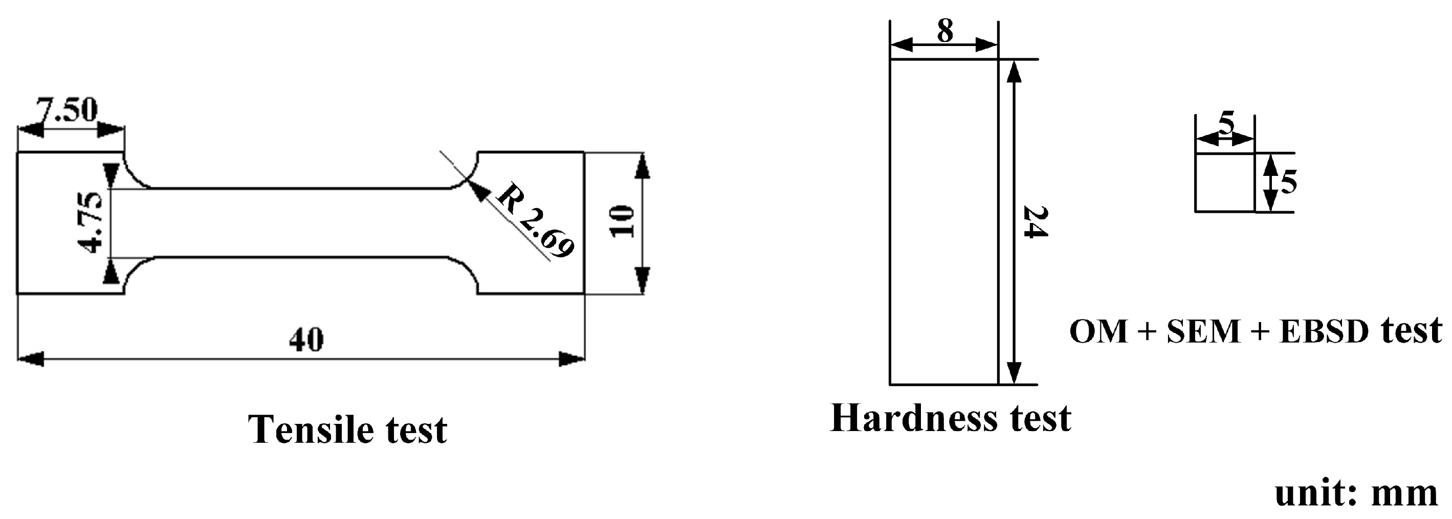
2. Materials and Methods
3. Results
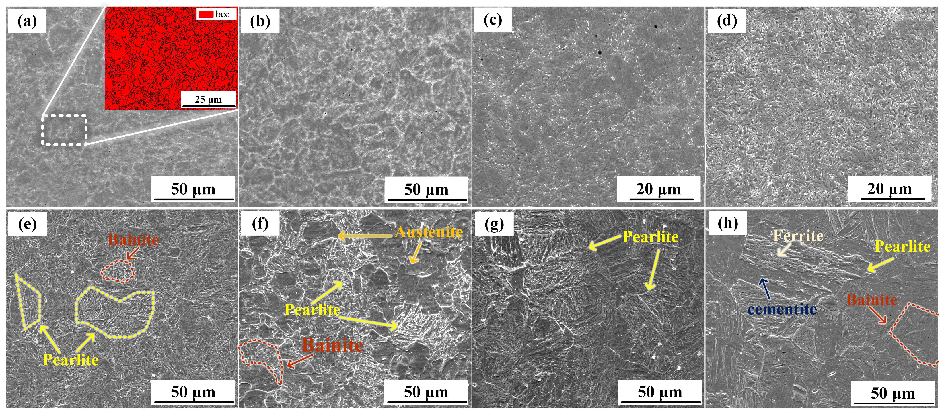
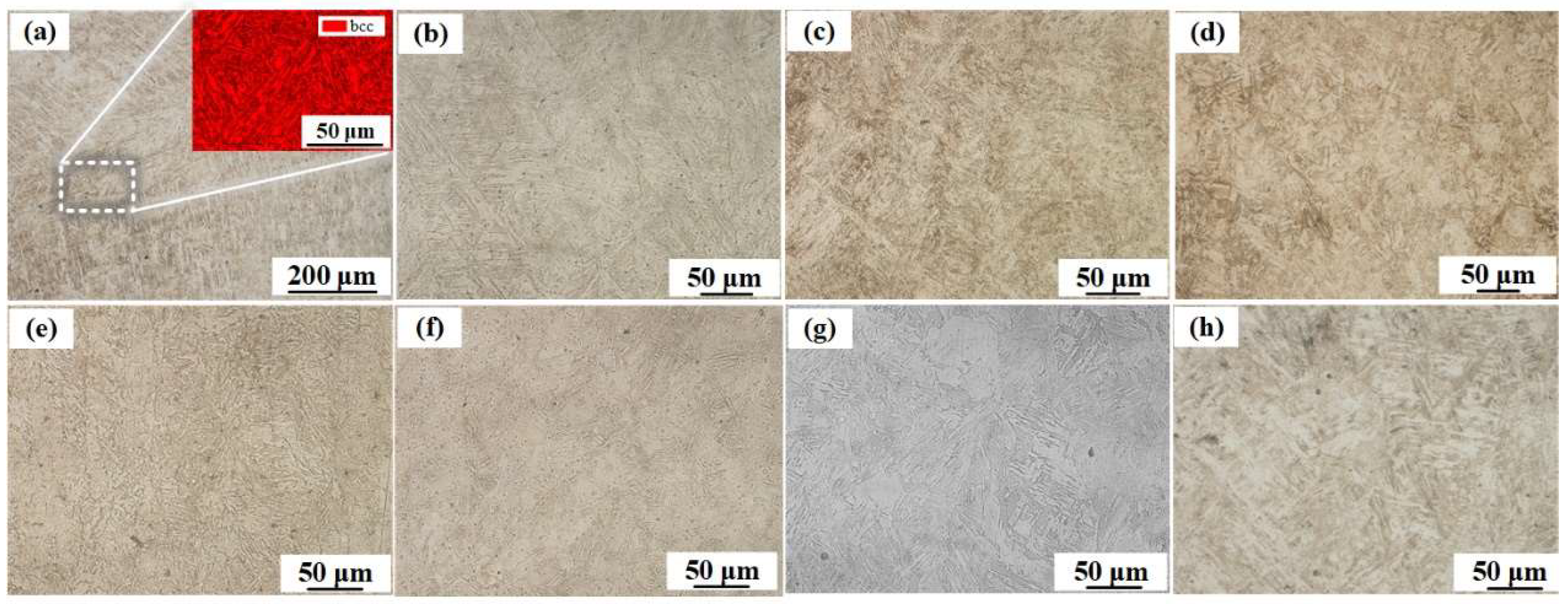
3.1. Microstructure
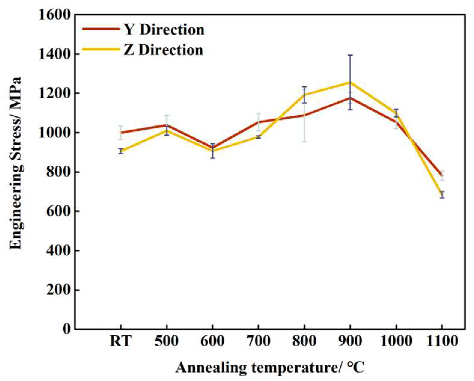
3.2. Mechanical Properties
4. Conclusions
- (1)
- With increasing annealing temperatures, the microstructure in the LCS layer changed from ferrite to a mixture of phases, while the microstructure in the SS layer remained martensite.
- (2)
- As the annealing temperature increases, the grain-selective orientation in the LCS and SS304 layers gradually increases. In the LCS layer, when the annealing temperature reaches 1000 °C, the grains are predominantly oriented in the <110> direction. The FCC structure that appears in the SS304 layer after the annealing treatment is significantly oriented along the <111> direction, which is related to the minimization of the <111> surface energy during austenite recrystallization.
- (3)
- The optimal annealing temperature for this steel was 900 °C. At this temperature, finer pearlite and martensite formed in the LCS layer and SS304 layer, respectively. The steel exhibited maximum tensile strengths of 1176 MPa along the Y direction and 1255 MPa along the Z direction, which was 117.6% and 138.6% of the tensile strength at room temperature.
- (4)
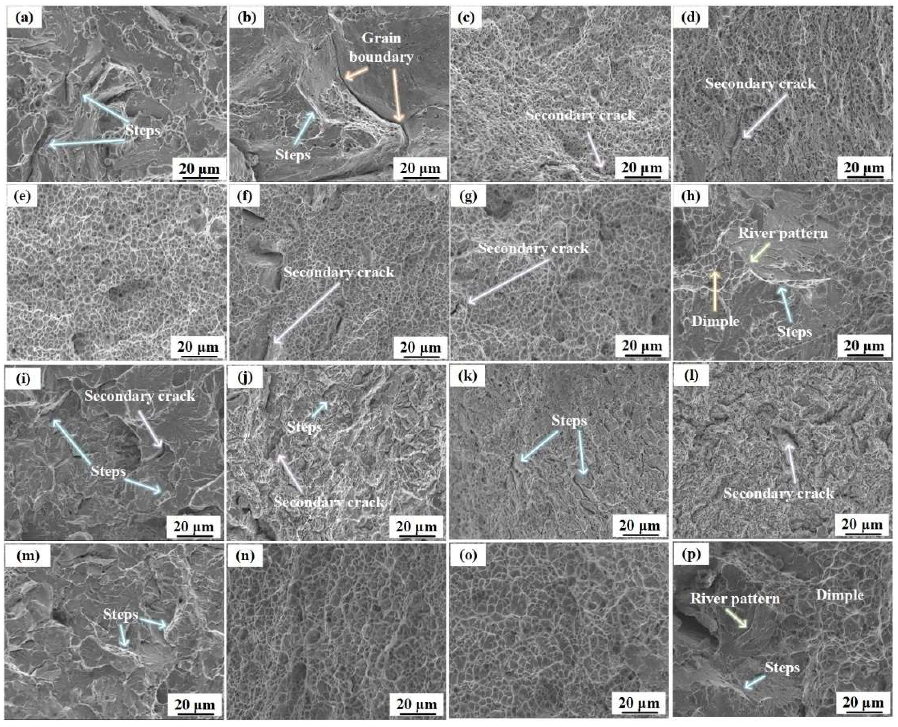
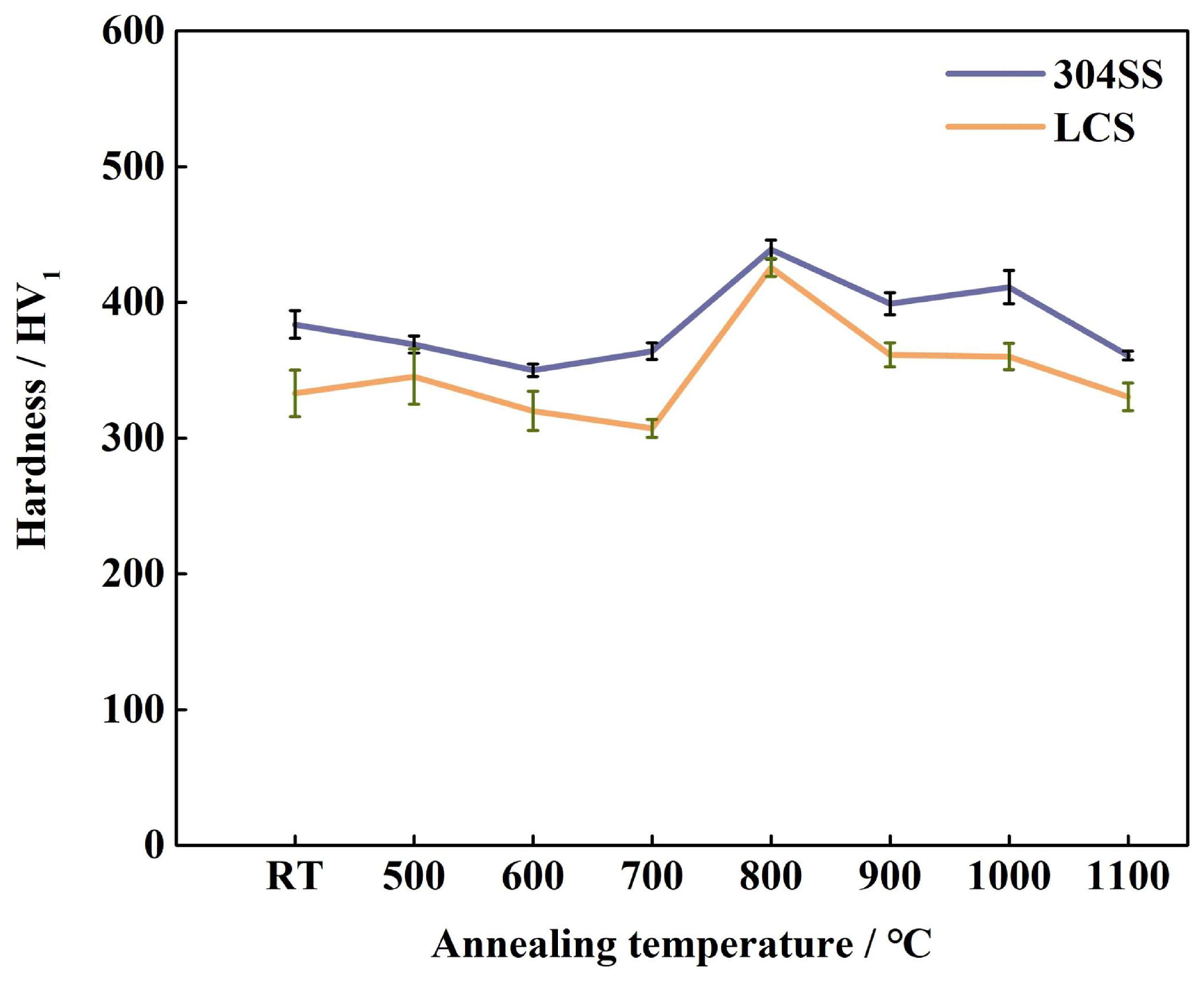
- All Z-directional fractures in the tensile testing occurred in the LCS layer because the martensite in the SS304 layer has a higher microhardness.
Author Contributions
Funding
Institutional Review Board Statement
Informed Consent Statement
Data Availability Statement
Conflicts of Interest
References
- Karthik, G.M.; Kim, H.S. Heterogeneous Aspects of Additive Manufactured Metallic Parts: A Review. Met. Mater. Int. 2021, 27, 1–39. [Google Scholar] [CrossRef]
- Li, K.; Yang, T.; Gong, N.; Wu, J.; Wu, X.; Zhang, D.Z.; Murr, L.E. Additive manufacturing of ultra-high strength steels: A review. J. Alloys Compd. 2023, 965, 171390. [Google Scholar] [CrossRef]
- Avrampos, P.; Vosniakos, G.C. A review of powder deposition in additive manufacturing by powder bed fusion. J. Manuf. Process. 2022, 74, 332–352. [Google Scholar] [CrossRef]
- Negi, S.; Nambolan, A.A.; Kapil, S.; Joshi, P.S.; Manivannan, R.; Karunakaran, K.P.; Bhargava, P. Review on electron beam based additive manufacturing. Rapid Prototyp. J. 2020, 26, 485–498. [Google Scholar] [CrossRef]
- Kumar, N.; Bhavsar, H.; Mahesh, P.V.S.; Srivastava, A.K.; Bora, B.J.; Saxena, A.; Dixit, A.R. Wire arc additive manufacturing—A revolutionary method in additive manufacturing. Mater. Chem. Phys. 2022, 285, 126144. [Google Scholar] [CrossRef]
- Ahmet, E.F.E.; Abdullah, A. A general view of industry 4.0 revolution from cybersecurity perspective. Int. J. Intel. Syst. Appl. Eng. 2020, 8, 11–20. [Google Scholar]
- Liu, Z.; He, B.; Lyu, T.; Zou, Y. A review on additive manufacturing of titanium alloys for aerospace applications: Directed energy deposition and beyond Ti-6Al-4V. JOM 2021, 73, 1804–1818. [Google Scholar] [CrossRef]
- Salunkhe, S.; Rajamani, D. 3—Current trends of metal additive manufacturing in the defense, automobile, and aerospace industries. In Advances in Metal Additive Manufacturing; Reviews: Mechanical Engineering Series; Woodhead Publishing: Sawston, UK, 2023; pp. 413–429. [Google Scholar]
- Grässel, O.; Krüger, L.; Frommeyer, G.; Meyer, L.W. High strength Fe–Mn– (Al, Si), TRIP/TWIP steels development properties application. Int. J. Plast. 2000, 16, 1391–1409. [Google Scholar] [CrossRef]
- Harada, N.; Uesugi, T.; Takigawa, Y.; Higashi, K. Improvement of high temperature strength by addition of vanadium content of Ni–Cr–Mo steel for brake discs. ISIJ Int. 2017, 57, 550–557. [Google Scholar] [CrossRef]
- Atta-Agyemang, S.A.; Kesse, M.A.; Kah, P.; Martikainen, J. Improvement of strength and toughness: The effect on the weldability of high-strength steels used in offshore structures. Proc. Inst. Mech. Eng. Part B J. Eng. Manuf. 2017, 231, 369–376. [Google Scholar] [CrossRef]
- Coelho, A.M.G.; Bijlaard, F. High strength steel in buildings and civil engineering structures: Design of connections. Adv. Struct. Eng. 2010, 13, 413–429. [Google Scholar] [CrossRef]
- Zhang, J.; Zhang, J.; Ding, X. Evaluation of shrinkage and fracture properties of internal cured 100-MPa ultrahigh-strength steel fiber–reinforced concrete. J. Mater. Civ. Eng. 2017, 29, 06017016. [Google Scholar] [CrossRef]
- Mei, L.; Chen, G.; Jin, X.; Zhang, Y.; Wu, Q. Research on laser welding of high-strength galvanized automobile steel sheets. Opt. Lasers Eng. 2009, 47, 1117–1124. [Google Scholar] [CrossRef]
- Kuziak, R.; Kawalla, R.; Waengler, S. Advanced high strength steels for automotive industry. Arch. Civ. Mech. Eng. 2008, 8, 103–117. [Google Scholar] [CrossRef]
- Qiang, X.; Jiang, X.; Bijlaard, F.S.K.; Kolstein, H. Mechanical properties and design recommendations of very high strength steel S960 in fire. Eng. Struct. 2016, 112, 60–70. [Google Scholar] [CrossRef]
- Ueji, R.; Harada, K.; Tsuchida, N.; Kunishige, K. High speed deformation of ultrafine grained TWIP steel. Mater. Sci. Forum 2007, 561–565, 107–110. [Google Scholar] [CrossRef]
- El-Tahawy, M.; Pereira, P.H.R.; Huang, Y.; Park, H.; Choe, H.; Langdon, T.G.; Gubicza, J. Exceptionally high strength and good ductility in an ultrafine-grained 316L steel processed by severe plastic deformation and subsequent annealing. Mater. Lett. 2018, 214, 240–242. [Google Scholar] [CrossRef]
- Yan, F.K.; Liu, G.Z.; Tao, N.R.; Lu, K. Strength and ductility of 316L austenitic stainless steel strengthened by nano-scale twin bundles. Acta Mater. 2012, 60, 1059–1071. [Google Scholar] [CrossRef]
- Chen, A.Y.; Ruan, H.H.; Wang, J.; Chan, H.L.; Wang, Q.; Li, Q. The influence of strain rate on the microstructure transition of 304 stainless steel. Acta Mater. 2011, 59, 3697–3709. [Google Scholar] [CrossRef]
- Ueno, H.; Kakihata, K.; Kaneko, Y.; Hashimoto, S.; Vinogradov, A. Enhanced fatigue properties of nanostructured austenitic SUS 316L stainless steel. Acta Mater. 2011, 59, 7060–7069. [Google Scholar] [CrossRef]
- Matsuda, H.; Mizuno, R.; Funakawa, Y.; Seto, K.; Matsuoka, S.; Tanaka, Y. Effects of auto-tempering behavior of martensite on mechanical properties of ultra-high strength steel sheets. J. Alloys Compd. 2013, 577, S661–S667. [Google Scholar] [CrossRef]
- Mine, Y.; Horita, Z.; Murakami, Y. Effect of hydrogen on martensite formation in austenitic stainless steels in high-pressure torsion. Acta Mater. 2009, 57, 2993–3002. [Google Scholar] [CrossRef]
- Martin, J.H.; Yahata, B.D.; Hundley, J.M.; Mayer, J.A.; Schaedler, T.A.; Pollock, T.M. 3D printing of high-strength aluminium alloys. Nature 2017, 549, 365–369. [Google Scholar] [CrossRef]
- Mereddy, S.; Bermingham, M.J.; StJohn, D.H.; Dargusch, M.S. Grain refinement of wire arc additively manufactured titanium by the addition of silicon. J. Alloys Compd. 2016, 695, 2097–2103. [Google Scholar] [CrossRef]
- Fang, Q.; Zhao, L.; Liu, B.; Chen, C.; Peng, Y.; Tian, Z.; Yin, Y. Microstructure and Mechanical Properties of 800-MPa-Class High-Strength Low-Alloy Steel Part Fabricated by Wire Arc Additive Manufacturing. J. Mater. Eng. Perform. 2022, 31, 7461–7471. [Google Scholar] [CrossRef]
- Jing, C.; Chen, Z.; Liu, B.; Xu, T.; Wang, J.; Lu, T.; Lu, J.; Guo, Y.; Liu, C. Improving mechanical strength and isotropy for wire-arc additive manufactured 304L stainless steels via controlling arc heat input. Mater. Sci. Eng. A 2022, 845, 143223. [Google Scholar] [CrossRef]
- Jin, X.; Li, X.; Zhao, G.; Shao, L.; Wang, H.; Deng, Y.; Chen, Y.; Gao, Y. Research on transition layer microstructure and properties of Al–Cu/Al–Si gradient materials fabricated by cold metal transfer. J. Mater. Res. Technol. 2023, 25, 3835–3846. [Google Scholar]
- Ayan, Y.; Kahraman, N. Fabrication and characterization of functionally graded material (FGM) structure containing two dissimilar steels (ER70S-6 and 308LSi) by wire arc additive manufacturing (WAAM). Mater. Today Commun. 2022, 33, 104457. [Google Scholar] [CrossRef]
- Chen, Y.; Zuo, X.; Zhang, W.; Hao, Z.; Li, Y.; Luo, Z.; Ao, S. Enhanced strength-ductility synergy of bimetallic laminated steel structure of 304 stainless steel and low-carbon steel fabricated by wire and arc additive manufacturing. Mater. Sci. Eng. A 2022, 856, 143984. [Google Scholar] [CrossRef]
- Chen, L.; Wen, Y.; Li, J. A multiscale investigation of deformation heterogeneity in additively manufactured 316L stainless steel. Mater. Sci. Eng. A 2021, 820, 141493. [Google Scholar] [CrossRef]
- Ji, X.; Xie, H.; Su, J.; Jiang, F.; Jie, T.; Zhang, H.; Guo, B. Phase Transformation Behaviors and Dislocation Evolutions of an Additively Manufactured Ti-6Al-4V Alloy under Annealing Treatment. Metals 2023, 13, 1061. [Google Scholar] [CrossRef]
- Yu, F.; Zhang, Y.; Kong, C.; Yu, H. High strength and toughness of Ti–6Al–4V sheets via cryorolling and short-period annealing. Mater. Sci. Eng. A 2022, 854, 143766. [Google Scholar] [CrossRef]
- Ng, C.K.; Bai, K.; Wuu, D.; Lau, K.B.; Lee, J.J.; Cheong, A.K.H.; Wei, F.; Cheng, B.; Wang, P.; Tan, D.C.C.; et al. Additive manufacturing of high-strength and ductile high entropy alloy CoCrFeNiW0.2 composites via laser powder bed fusion and post-annealing. J. Alloys Compd. 2022, 906, 164288. [Google Scholar] [CrossRef]
- Gu, Y.; Yuan, J.; Chen, L. Switching of control mechanisms during the rapid solidification of a melt pool. Phys. Rev. Mater. 2023, 7, 103401. [Google Scholar] [CrossRef]
- Di Schino, A.; Testani, C. Heat Treatment of Steels. Metals 2021, 11, 1168. [Google Scholar] [CrossRef]
- Song, Q.; Chen, X. Corrosive and diffusive behaviors of Cu in the aluminum brazed joints. J. Gansu Univ. Technol. 2002, 28, 19–22. [Google Scholar]
- Liu, Y. Study on Microstructure Transformation and Mechanical Behavior of Welded Joints of Q345C Steel. Master’s Thesis, Southwest Jiaotong University, Chengdu, China, 2017. [Google Scholar]
- Tsuchida, N.; Tomota, Y.; Nagai, K. High-speed deformation for an ultrafine-grained ferrite-pearlite steel. ISIJ Int. 2002, 42, 1594–1596. [Google Scholar] [CrossRef]
- Wang, B.; Zhang, X.; Jia, T.; Wang, B.; Li, Y.; Tian, Y.; Wang, Z.; Wang, G. Transformation Mechanism and Precipitation Behavior of Nanoscale Cementite in Carbon Steels during Ultrafast Cooling. Steel Res. Int. 2022, 93, 2100686. [Google Scholar] [CrossRef]
- Michal, G.M.; Ernst, F.; Heuer, A.H. Carbon paraequilibrium in austenitic stainless steel. Met. Mater Trans A 2006, 37, 1819–1824. [Google Scholar] [CrossRef]
- Benitez, R.; Gao, H.; O'Neal, M.; Lovelace, P.; Proust, G.; Radovic, M. Effects of microstructure on the mechanical properties of Ti2AlC in compression. Acta Mater. 2017, 143, 130–140. [Google Scholar] [CrossRef]
- Mirshekari, B.; Zarei-Hanzaki, A.; Barabi, A.; Moshiri, A.; Abedi, H.R.; Lee, S.J.; Fujii, H. Optimizing the austenite stability in a ferritic lightweight steel through thermomechanical processing. Mater. Charact. 2020, 166, 110367. [Google Scholar] [CrossRef]
- Wang, B.; Zhang, J.M.; Lu, Y.D.; Gan, X.Y.; Yin, B.X.; Xu, K.W. Anisotropy analysis of surface energy and prediction of surface segregation for fcc metals. Acta Phys. Sin. 2011, 60, 506–514. [Google Scholar] [CrossRef]
- Guo, H.; Zhou, P.; Zhao, A.M.; Zhi, C.; Ding, R.; Wang, J.X. Effects of Mn and Cr contents on microstructures and mechanical properties of low temperature bainitic steel. J. Iron Steel Res. Int. 2017, 24, 290–295. [Google Scholar] [CrossRef]
- Xu, S.; Lu, Q.; Ou, Y.; Zhang, P.; Yan, H.; Sun, T.; Ma, S.; Luo, Z.; Tian, Y. Effect of Heat Treatment on the Anisotropic Mechanical Properties of AlSi10Mg Fabricated by Selective Laser Melting. J. Mater. Eng Perform. 2023. [Google Scholar] [CrossRef]
- Xu, K.; Jiang, H.; Yan, J.B.; Zhang, P.; Liu, P.; Cao, G.H.; Yuan, Y. Tensile properties and deformation mechanisms of a solution treated Ni–Fe-based alloy at high temperatures. Mater. Sci. Eng. A 2023, 881, 145418. [Google Scholar] [CrossRef]
- Merson, E.D.; Myagkikh, P.N.; Poluyanov, V.A.; Merson, D.L.; Vinogradov, A. Quasi-cleavage hydrogen-assisted cracking path investigation by fractographic and side surface observations. Eng. Fract. Mech. 2019, 214, 177–193. [Google Scholar] [CrossRef]
- Shen, B.; Li, L.; Yue, C. Summarization of Relationship between Tensile Strength and Hardness of Iron Steel Materials. Mod. Cast Iron 2012, 32, 93–96. [Google Scholar]


| Materials | C | Mn | P | S | Si | Cr | Ni | Cu | Fe |
|---|---|---|---|---|---|---|---|---|---|
| 304 SS | ≤0.07 | ≤2 | ≤0.045 | ≤0.03 | ≤1 | 18–20 | 8–11 | 0 | Bal. |
| LCS | 0.06–0.15 | 1.40–1.85 | ≤0.025 | ≤0.035 | 0.8–1.15 | 0 | 0 | ≤0.5 | Bal. |
| Type | DOF | Maximum Handling Weight (kg) | Weight (kg) | Maximum Reach Distance (mm) |
|---|---|---|---|---|
| YA-1VAR61CJ0 | 6 | 6 | 170 | 1437.5 |
| Type | Rated Power (kW) | Range of Output Current (A) | Range of Output Voltage (V) |
|---|---|---|---|
| YD-350GL | 13.5 | 40~430 (without pulse) 40~350 (with pulse) | 16~35.5 (without pulse) 16~31.5 (with pulse) |
Disclaimer/Publisher’s Note: The statements, opinions and data contained in all publications are solely those of the individual author(s) and contributor(s) and not of MDPI and/or the editor(s). MDPI and/or the editor(s) disclaim responsibility for any injury to people or property resulting from any ideas, methods, instructions or products referred to in the content. |
© 2023 by the authors. Licensee MDPI, Basel, Switzerland. This article is an open access article distributed under the terms and conditions of the Creative Commons Attribution (CC BY) license (https://creativecommons.org/licenses/by/4.0/).
Share and Cite
Chen, Y.; Hao, Z.; Li, Y.; Liu, C.; Liu, Y.; Luo, Z.; Ao, S. Enhancing Mechanical Properties: Exploring the Effect of Annealing Temperature on Wire Arc Additively Manufactured High-Strength Steel. Materials 2023, 16, 6969. https://0-doi-org.brum.beds.ac.uk/10.3390/ma16216969
Chen Y, Hao Z, Li Y, Liu C, Liu Y, Luo Z, Ao S. Enhancing Mechanical Properties: Exploring the Effect of Annealing Temperature on Wire Arc Additively Manufactured High-Strength Steel. Materials. 2023; 16(21):6969. https://0-doi-org.brum.beds.ac.uk/10.3390/ma16216969
Chicago/Turabian StyleChen, Yi, Zhizhuang Hao, Yang Li, Chao Liu, Yongkang Liu, Zhen Luo, and Sansan Ao. 2023. "Enhancing Mechanical Properties: Exploring the Effect of Annealing Temperature on Wire Arc Additively Manufactured High-Strength Steel" Materials 16, no. 21: 6969. https://0-doi-org.brum.beds.ac.uk/10.3390/ma16216969