Article

Optimally Splitting Solar Spectrums by Concentrating Solar Spectrums Splitter for Hydrogen Production via Solid Oxide Electrolysis Cell

1
Faculty of Maritime and Transportation, Ningbo University, Ningbo 315211, China
2
College of New Energy, Ningbo University of Technology, Ningbo 315211, China
*
Authors to whom correspondence should be addressed.
Submission received: 25 March 2024 / Revised: 22 April 2024 / Accepted: 25 April 2024 / Published: 26 April 2024
(This article belongs to the Special Issue Solar Cells, Circuits and Systems for PV Conversion)

Abstract

:
The concentrating solar spectrums splitter (CSSS)-driven solid oxide electrolysis cell (SOEC) is an attractive technology for green hydrogen production. The CSSS mainly comprises a concentrating photovoltaic (CPV), which converts sunlight with shorter wavelengths into electricity, and a concentrating solar collector (CSC), which converts the remaining sunlight into heat. However, the optimal splitting of the solar spectrums is a critical challenge that directly impacts the efficiency and normal operation of the SOEC. To address this challenge, a mathematical model integrating the CSSS with the SOEC is developed based on principles from thermodynamics and electrochemistry. By analyzing the requirements of electricity and heat for the SOEC, the model determines the optimal configuration and operational parameters. The results show that the anode-supported type, higher operating temperature, larger inlet flow rate of water, higher operating pressure of the SOEC, higher operating temperature of the CSC, and larger electric current of the CPV contribute to allocating more solar spectrums to the CSC for heat generation. However, the greater effectiveness of the heat exchangers, higher operating temperature, and larger optical concentration ratio of the CPV exhibit contrasting effects on the spectrum allocation. The obtained results provide valuable theoretical guidance for designing and running the CSSS for hydrogen production through SOEC.

1. Introduction

Due to swift economic growth and global population expansion, there has been a substantial surge in the consumption of fossil fuels. Unfortunately, this trend has resulted in adverse consequences, such as global warming [1], environmental pollution [2], and resource scarcity [3], thereby impeding the progress of social sustainability. Consequently, it has become exceedingly urgent to develop low-carbon, clean, and efficient renewable energy sources. Hydrogen can be regarded as a feasible solution to address environmental disruption and energy challenges [4]. It possesses excellent combustion properties and a high energy density, and it does not produce emissions of greenhouse gases, such as carbon dioxide, nitrogen oxides, and sulfur oxides, making it a safe and reliable energy option [5,6]. Moreover, hydrogen is easy to store and transport, making it highly versatile and applicable in various fields [7,8]. These inherent characteristics position hydrogen as a pivotal component in the development of sustainable energy carriers [9].
Currently, there are several technologies available for hydrogen production from water decomposition, including electrolysis, photocatalytic processes, and thermochemical processes [10]. Among them, water electrolysis has gained significant attention as a hydrogen production method due to its high purity and environmentally friendly nature [11]. However, due to the large amount of electricity required, it is relatively expensive in terms of cost-effectiveness [12,13]. Solar energy, as the most plentiful and environmentally friendly renewable energy source, presents a promising solution for hydrogen production by integrating photovoltaic conversion and electrolysis [14,15]. This approach not only reduces the cost of hydrogen production but also enables the storage of intermittent and fluctuating solar energy in the form of hydrogen fuel. Compared to low-temperature electrolysis, such as proton exchange membrane electrolysis cells and alkaline water electrolysis cells, solid oxide electrolysis cell (SOEC) has a notable cost advantage [16]. This is primarily attributed to the utilization of a high operating temperature, which minimizes the electrical energy requirement, enhances electrode activity, and reduces overpotentials during the electrochemical processes [17,18,19,20]. The fundamental principle behind the use of solar-driven SOEC for hydrogen production involves the efficient utilization and splitting of the solar spectrums using a concentrating solar spectrums splitter (CSSS). The CSSS effectively directs sunlight to a concentrating photovoltaic (CPV) system and a concentrating solar collector (CSC) [21,22,23,24]. The CPV system converts the shorter wavelengths of solar energy into electricity, while the CSC collects and converts the remaining wavelengths of solar energy into heat. The electricity and heat generated by the CPV and CSC are then supplied to the SOEC for hydrogen production [25,26,27]. Consequently, the hybrid system combining CSSS and SOEC technologies holds great promise for efficient and sustainable hydrogen production.
Given the compatibility and feasibility between the CSSS and SOEC, numerous studies have been conducted to advance this technology, including efficiency evaluation, the influential mechanism, protype demonstration, economic assessment, and deficiencies. For example, Edwards et al. [28] proposed a scheme to use CSSS to provide electricity and heat to SOEC for hydrogen production, which could achieve a theoretical efficiency of approximately 50%. However, due to energy losses or mismatches between the provided electrical and thermal energy, a practical efficiency of 30% or more was obtained. Mittelman et al. [29] presented a concept for the production of solar fuels based on CSSS and SOEC, achieving peak hydrogen production efficiencies of 23.0% and 33.1% using mono-Si and GaAs/Si photovoltaic component materials with cutoff wavelengths of 1200 nm . Once the electrical and thermal energy provided by the CSSS changed, it inevitably led to a decrease in the efficiency of the CSSS-SOEC system. Daneshpour et al. [30] introduced a novel device that combined solar thermophotovoltaic with SOEC to efficiently harness solar energy by using CSSS for hydrogen production, achieving a hydrogen production efficiency of up to 34% with the InGaAsSb photovoltaic cell. However, the assignment of thermal and electrical energy required by SOEC was limited by the cutoff wavelength of the photovoltaic cell. Kaleibari et al. [31] conducted a study on a CSSS-driven SOEC for hydrogen production, reaching a hydrogen production efficiency of 36.5% under optimal conditions of a direct normal irradiance of 899 W   m 2 and a concentration of 1000 suns. Although three single-junction cells expanded the range of cutoff wavelengths, the assignment of thermal and electrical energy required by the SOEC was still limited by the cutoff wavelengths of the solar cells. Gopalan et al. [32] investigated the influence of various operational parameters on the hydrogen production efficiency in a CSSS-SOEC hybrid system, showing that operating above the thermal-neutral voltage could enhance hydrogen production efficiency. Nevertheless, a detailed analysis of the thermal and electrical energy required by SOEC was not discussed. Lin et al. [33] performed a techno-economic analysis and found that a SOEC driven by thermal and electrical energy from a CSSS achieved the highest hydrogen production efficiency and lowest cost, while ignoring the thermal and electrical energy requirements of the SOEC. Thompson et al. [34] conducted a cost analysis of CSSS-SOEC while the thermal and electrical energy requirements of CSSS-SOEC were not discussed.
However, the heat and electricity provided by the CSSS are not always well-matched with the real requirements of the SOEC, which may lead to chemical/electrochemical degradation [35], fragile component fractures [36], mechanical failures [37], and energy losses [38]. To address this issue, some scholars have introduced various new methods and system configurations to balance the supply of heat and electricity, aiming to efficiently utilize the inlet solar spectrums. For example, Liu et al. [38] optimized the supply-and-demand matching of electrical and thermal energy in a CSSS-SOEC system, achieving a hydrogen production efficiency of 39.0% under optimal conditions with a cutoff wavelength of 1000 nm and a reaction temperature of 950 °C. However, this electrical and thermal energy matching method had strict conditional limitations. Baniasadi [39] introduced a new process for the high-efficiency production of a hydrogen system and saltwater desalination based on CSSS, achieving maximum energy and exergy efficiencies of about 45%. While this method of matching electrical and thermal energy improves the efficiency of the hybrid system, it also restricts the efficiency of CSSS-SOEC. Fang et al. [40] proposed a system integrating CSSS with thermochemical methane steam reforming and the Rankine cycle to balance the electricity and heat supply for SOEC hydrogen production. This new concept helps balance the supply of heat and electricity. However, this method may lead to greater system complexity and higher manufacturing costs. Therefore, it is quite important to optimally split the solar spectrums by using the CSSS to meet the electricity and heat requirements of the SOEC, which may not only reduce the manufacturing cost and system complexity, but also improve energy efficiency and operation durability.
In this work, a hybrid-system model incorporating CSSS and SOEC is formulated to discuss how to optimally split the solar spectrums according to the requirements of heat and electricity of SOEC. Firstly, the SOEC electrochemical model is described, and the requirements of electricity and heat are determined, deriving the balance parameter to guide the CSSS to allocate the solar spectrums. Later, the CSSS model is described to determine how much electric power can be delivered. Subsequently, the models of the SOEC and the CPV within the CSSS are validated using the experimental data. Finally, the dependences of the balance parameter and the cut-off wavelength splitting the solar spectrums on various design or operating parameters are discussed, providing fresh perspectives on the design and operation of a real-world solar–hydrogen system.

2. System Descriptions

Figure 1 shows the schematic diagram of a concentrating solar spectrums splitter (CSSS)-powered solid oxide electrolysis cell (SOEC) for the eco-friendly production of hydrogen. The system consists of several components, including a CSSS with a concentrating photovoltaic (CPV) and a concentrating solar collector (CSC), an SOEC, a separator, two heat exchangers, and two product tanks. The solar energy is converted into both electricity and heat by the CSSS, which is then utilized by the SOEC for hydrogen production. Because the products exiting the SOEC contain a considerable quantity of waste heat, most of the waste heat can be reclaimed by utilizing heat exchanger #1 to warm the incoming water. Once it passes through heat exchanger #1, the oxygen undergoes a cooling process and is subsequently stored. The H 2 / H 2 O mixture is then channeled into the separator, where it undergoes an efficient separation process. The hydrogen is subjected to cooling and subsequently stored as a source of fuel, while the hot water from the separator is blended with the incoming water for use in the subsequent hydrogen production cycle. The feeding steam needs to be further heated when passing across heat exchanger #2 to attain the temperature required for the SOEC reaction [41].
To simplify the subsequent analyses, several basic model assumptions are made:
(1)
The hybrid system operates continuously under stable and consistent conditions;
(2)
All wavelengths of sunlight entering the system are utilized [42];
(3)
Ideal gas properties are assumed for all the working gases [43];
(4)
The working fluids are considered homogeneous and continuous, and effects such as viscous heat dissipation, pressure drop, kinetic energy, and potential energy are neglected [44];
(5)
Negligible heat losses occur in the pipelines [45];
(6)
All electrochemical reactions in thermochemical cycles occur at the reaction temperature and with a pressure of 1 atm [46];
(7)
The increases in thermal conductance and electrical resistance resulting from the operation of the coupling system are negligible;
(8)
SOEC operates in isothermal mode [47];
(9)
Contact resistances are ignored [48].

2.1. Solid Oxide Electrolysis Cell

As illustrated in Figure 1, CSSS is utilized to supply high-temperature heat and electricity for driving the electrochemical reaction of SOEC, resulting in the decomposition of H 2 O into H 2 and O 2 [49,50,51,52]:
2 H 2 O + heat + electricity 2 H 2 + O 2
The total energy requirement can be expressed as follows:
Δ H ( T ) = Δ G ( T ) + Q ( T )
where Δ G ( T ) , Q ( T ) = T Δ S ( T ) , and Δ S ( T ) are the Gibbs energy change, heat requirement, and entropy change, respectively, and T is the SOEC’s operating temperature. These thermodynamic parameters can be derived through the computations detailed in [53].
The equilibrium potential of the SOEC can be determined by the Nernst equation, which calculates the lowest electric potential required to facilitate the splitting at a specified temperature and gas concentration [50,54]:
E = E 0 + R T 2 F ln ( P H 2 P O 2 1 / 2 P H 2 O )
where E 0 = 1.253 2.4516 × 10 4 T .
Extra voltage is required to overcome the irreversible overpotentials and ensure normal operation in SOEC, where the irreversible potentials include activation overpotential, concentration overpotential, and ohmic overpotential [50,54,55].
(1)
Activation overpotential
According to the Butler–Volmer equation, the activation overpotential V a c t , k can be expressed as [50,54,56]
V a c t , k = R T F sinh 1 ( J 2 J 0 , k ) = R T F [ J 2 J 0 , k + ( J 2 J 0 , k ) 2 + 1 ] ,   k = a , c
where J 0 , k = γ k e E a c t , k R T and subscript k represents the letters of a or c for anode or cathode, respectively.
(2)
Concentration overpotential
The cathode and anode concentration overpotentials can be, respectively, calculated by [54,57,58,59]
V c o n , a = R T 4 F ln ( ( P O 2 ) 2 + J R T μ 2 F B g L a P O 2 )
and
V c o n , c = R T 2 F ln [ 1 + ( J R T L c / 2 F D H 2 O e f f P H 2 ) 1 ( J R T L c / 2 F D H 2 O e f f P H 2 O ) ]
(3)
Ohmic overpotential
According to Ohm’s law, the ohmic overpotential can be expressed as [17,49,60,61]
V o h m = J R o h m = J ( L a σ a + L e σ e + L c σ c )
The input potential of an SOEC to drive the SOEC for hydrogen production can be expressed as the sum of the equilibrium potential E and the extra voltage attributed to all the irreversible losses, as follows:
V = E + V a c t , a + V a c t , c + V c o n , a + V c o n , c + V o h m
The electrical power P S O E C required by a single SOEC can be calculated as follows:
P S O E C = V I
where I = J A S O E C .
Furthermore, the rate of entropy generation δ resulting from irreversible overpotentials involved in the operation of SOEC can be calculated as follows:
δ = 2 F ( V a c t , a + V a c t , c + V c o n , a + V c o n , c + V o h m )
Additionally, according to Faraday’s law, the rate of electrochemical reaction ν S O E C in the SOEC is dependent on the operating electric current I [62,63]:
ν S O E C = ± d n d t = I 2 F
According to Equation (11), the outlet flow rate of H 2 O is given by
N · H 2 , o u t = 2 N · O 2 , o u t = N · H 2 O , r e a c t e d = I 2 F
and
N · H 2 O , o u t = N · H 2 O , i n N · H 2 O , r e a c t e d = N · H 2 O , i n I 2 F
So, the heat input to the SOEC can be expressed as [57]
Q S O E C = N · H 2 O , r e a c t e d [ T Δ S δ ]
The heat required for heating the supplementary water per unit time Q H 2 O can be formulated as [64,65]
Q H 2 O = [ N · H 2 O , i n ( 1 ε 1 ) + I 2 F ] ( T 0 T b C H 2 O ( l ) d T + L v + T b T C H 2 O ( g ) d T ) I 2 F T 0 T ( C P , H 2 + 1 2 C P , O 2 d T )
where C p , m (m = H 2 O , H 2 , or O 2 ).
So, a balance parameter χ defined as the ratio of electricity to the total exergy of the SOEC can be introduced [53] to find out exergy requirement of the SOEC under different conditions:
χ = P S O E C P S O E C + Q S O E C ( 1 T 0 T X ) + Q H 2 O ( 1 T 0 T C S C )
where T C S C is temperature of the heat provided by the CSC; T X may be equal to T C S C or T , which depends on the value of Q S O E C .
When Q S O E C > 0 , the heat produced from irreversible losses in the SOEC is not enough to meet the heat requirement for the desired reaction. This indicates that the SOEC alone cannot generate enough heat to meet the exergy demand required for the reaction; heat from the CSC is necessary to achieve the required exergy balance. As a result, Equation (16) should be modified to Equation (17), indicating that the electrolysis reaction process must be effectively carried out with the help of heat input from the CSC.
χ = P S O E C P S O E C + Q S O E C ( 1 T 0 T C S C ) + Q H 2 O ( 1 T 0 T C S C )
When Q S O E C 0 and Q S O E C ( 1 T 0 T ) + Q H 2 O ( 1 T 0 T C S C ) > 0 , the heat generated by the irreversible losses in the SOEC equals or exceeds the heat demanded by the water electrolysis reaction. This indicates that there is no supplementary heat input to supply the SOEC during the hydrogen production process. Furthermore, to optimize the utilization of excess heat generated by the SOEC, it is directed into heat exchanger #2, where it preheats H 2 O and reduces the heat supply burden on CSC, thereby improving the thermal exergy utilization in the hybrid system. In this case, Equation (16) can be modified as follows:
χ = P S O E C P S O E C + Q S O E C ( 1 T 0 T ) + Q H 2 O ( 1 T 0 T C S C )
When Q S O E C ( 1 T 0 T ) + Q H 2 O ( 1 T 0 T C S C ) 0 , the irreversible heat losses generated in SOEC are greater than or equal to the heat requirement of the water electrolysis process for hydrogen production, including the heat required by the SOEC itself and the heat provided by the CSC. To maintain SOEC in steady operation, redundant heat is simultaneously released into the atmosphere. In this case, Equation (16) can be modified into
χ = P S O E C P S O E C
This indicates that the balance parameter is constant at 100% throughout, and the hybrid system only requires electrical exergy to operate.

2.2. Concentrating Solar Spectrums Splitter

According to the interference principle of sunlight caused by the multilayer film, in the CSSS, sunlight is concentrated by the concentrator onto the spectral filter and split by the filter into two parts: one part, with relatively short wavelengths, is assigned to CPV, and the other part, with relatively long wavelengths, is assigned to CSC.
The total solar radiation energy Q S O L A R includes the energy received by the CPV of Q C P V , the CSC of Q C S C , and optical loss [66,67], i.e.,
Q S O L A R = A C D N I A M 1.5 = A C 0   nm +   nm E A M 1.5 ( λ )   d λ
Q C P V = η o p t C C P V A C P V G C P V = η opt A C 0   nm x c   nm E A M 1.5 ( λ )   d λ
and
Q C S C = η o p t Q S O L A R Q C P V = η o p t A C x c   nm +   nm E A M 1.5 ( λ )   d λ

2.2.1. Concentrating Photovoltaic

Once the solar spectrums pass through the CSSS, the part of solar energy containing shorter wavelengths, Q C P V , is transmitted to the CPV and converted into electricity. The correlation between the output electric current I C P V and output voltage V C P V of CPV is given by [68,69]
I C P V = n p I L n p I 0 = n p I L n p I S { exp [ q ( V C P V + I C P V R S ) A K b T C P V n S ] 1 }
The photocurrent I L can be expressed as [49,60]
I L = G C P V G r [ C C P V I S C + K S C ( T C P V T 0 ) ]
The diode reverse saturation current I S is given by [68]
I S = C C P V I r ( T C P V T 0 ) 3 exp [ E g q K b ( 1 T 0 1 T C P V ) ]
The mathematical expression of V C P V , obtained by rearranging Equation (24), is given by [70,71]
V C P V = A K B T C P V n S q ln ( n P I L 1 n P I S + 1 ) I C P V R S
The power P C P V , the energy efficiency ηCPV, and the exergy efficiency ψ C P V of CPV can be, respectively, calculated by
P C P V = V C P V I C P V
η C P V = P C P V η o p t C C P V A C P V G C P V
and
ψ C P V = P C P V η o p t C C P V A C P V G C P V ( 1 4 T 0 3 T s u n + 1 3 ( T 0 T s u n ) 4 )

2.2.2. Concentrating Solar Collector

The CSC is a thermodynamic device that collects solar energy Q C S C and then radiates it to the absorber surface area. The absorber converts solar energy into heat and transfers it to the flowing fluid (usually air, water, or oil). Subsequently, the heat is transferred to the SOEC or heat exchangers through the flowing fluid as an intermediary medium, meeting the high-temperature heat requirements of both the SOEC and the heat exchangers [30,72].

2.3. Solar Spectrums Splitting in the Hybrid System

In order to effectively utilize CSSS to allocate solar spectrums for CPV electricity generation and CSC heat generation to meet the electricity and heat requirements of SOEC, the indirect coupling method (DC-DC) [73,74,75] is employed to achieve a perfect match between Equation (16) and the ratio of electricity generated by CPV to the sum of electricity generated by CPV and exergy gained from CSC, i.e.,
χ = P S O E C P S O E C + Q S O E C ( 1 T 0 T X ) + Q H 2 O ( 1 T 0 T C S C ) = P C P V P C P V + Q C S C ( 1 T 0 T C S C )
Equation (30) can be rewritten as
χ = P S O E C P S O E C + Q S O E C ( 1 T 0 T X ) + Q H 2 O ( 1 T 0 T C S C ) = ψ C P V 0   nm x c   nm E A M 1.5 ( λ )   d λ ψ C P V 0   nm x c   nm E A M 1.5 ( λ )   d λ + x c   nm +   nm E A M 1.5 ( λ )   d λ ( 1 T 0 T C S C )
where x c is the cut-off wavelength splitting the solar spectrum. Above this point, the solar spectrum is harnessed for heat generation, while below it, the solar spectrum is utilized for electricity generation.
From Equation (31), it can be observed that the balancing parameter of the hybrid system depends not only on the thermodynamic and electrochemical parameters of the SOEC, but also on the operation temperature of CSC. By utilizing the aforementioned equations, it is possible to analyze and optimize the CSSS to split solar spectrums for CPV generation electricity and for CSC generation heat to meet the requirements for the operating of SOEC. This helps achieve perfect matching between subsystems, enabling the efficient operation of the hybrid system [76,77].

3. Model Validation

Currently, there is a lack of experimental research on the solar spectrums split by CSSS for CPV electricity generation and CSC heat generation to drive SOEC hydrogen production. Consequently, the models of SOEC and CPV are validated independently. Figure 2a shows the potential of an SOEC V varying with steam molar fraction (SMF) under J   = 2000   A   m 2 , L e = 1.0 × 10 3   m , and T = 1273   K . The input parameters of the electrochemical model, along with their numerical values utilized in the calculations, are provided in Table 1 [78,79]. As the SMF increases, the SOEC potential decreases. This decrease is due to the application of the Nernst equation, which states that the potential decreases as the SMF increases. The modeling results demonstrate a strong concurrence with the experimental data collected by Momma et al. [80].
Figure 2b shows the CPV energy efficiency η C P V varying with the operating temperature T C P V under a band-gap energy of 1.12 eV, where G C P V = 800   W   m 2 , G r = 1000   W   m 2 , and T C P V = 300   K . The values of the input parameters specific to the CPV are documented in Table 2 [68]. It is shown that η C P V decreases as the operating temperature increases, and the modeling outcomes exhibit a notable congruence with the experimental findings detailed in [81].
In order to quantitatively assess the disparity between the modeling results and the experimental data, the average relative error can be computed following the methodology delineated in [82], i.e.,
A r e = 1 n i = 1 n | X c a l , i X exp , i X exp , i | × 100 %
where X c a l , i signifies the modeling results, while X e x p , i designates the experimental data. The average relative errors of the SOEC and CPV models are 2.4% and 1.95%, respectively. Consequently, the models for both the SOEC and the CPV are deemed to be trustworthy. The proposed hybrid system model is highly accurate, and its reliability can be guaranteed to a satisfactory degree.

4. Results and Discussion

In this section, the influences of some critical operational conditions and design parameters, including the support types, the operating temperature, the inlet flow rate of the water, the operating pressure of the SOEC, the effectiveness of the heat exchangers, the operating temperature, optical concentration ratio, the electric current of the CPV, and the operating temperature of the CSC, on the balance parameter ( χ ) and the cut-off wavelength splitting the solar spectrum ( x c ) are discussed. Thus, some useful suggestions on how to operate the CSSS for SOEC hydrogen production are given. Unless explicitly specified, the default parameters detailed in Table 1 and Table 2 are assumed for the calculations. The model of the CSSS-SOEC is solved using the iterative method by MATLAB R2018b software, and the detailed flow chart can be found in Figure 3.

4.1. Influences of the SOEC Support Types

The support types of the SOEC have a significant impact on the requirements of the electricity and heat, which not only affects the balance parameter χ , but also has a significant impact on the cut-off wavelength x c . The effects of the different support types of SOEC on χ and x c are illustrated in Figure 4. It is evident that χ sharply increases to attain 100% and that x c sharply increases to the upmost wavelength with the increase in J . Additionally, the growth rates of χ and x c for the electrolyte-supported SOEC are the largest, followed by those for the cathode-supported type and the anode-supported type. The situation of χ = 100 % means that all the inlet solar spectrums are assigned to the CPV by the CSSS for electricity generation. It is evident that the anode-supported type is the most optimal selection for the SOEC because it has the lowest electricity requirement. In the case of the anode-supported type, the porous structure does not pose an impediment to the transport of O 2 at the anode. Even for a thicker anode, there is no current limitation. Therefore, more solar spectrums can be assigned to the CSC by the CSSS for heat generation, which improves the hydrogen production efficiency. The cathode-supported SOEC maintains a consistent electricity requirement with the anode-supported SOEC at a small J . However, as J approaches the limiting current density of the cathode-supported SOEC, the electricity requirement increases sharply. The main reason for this is that the cathode concentration overpotential increases rapidly as the J of the cathode-supported SOEC approaches the limiting current density, leading to a sharp increase in the electricity requirement. In this regard, all the solar spectrums are assigned to the CPV by the CSSS for electricity generation. Additionally, the electrolyte-supported SOEC requires the highest amount of electricity to overcome the ohmic overpotential to drive O 2 through the dense electrolyte layer. Almost all the solar spectrums need to be assigned to the CPV by the CSSS for electricity generation to sustain the normal operation of the system, even when operating at a small J . Therefore, the anode-supported SOEC is adopted for subsequent analyses.

4.2. Influences of the SOEC Operating Temperature

The operating temperature of the SOEC T significantly affects the electricity and heat requirements, which in turn affects the balance parameter χ and the cut-off wavelength x c . As shown in Figure 5, χ increases to attain 100 % and x c increases to the upmost wavelength with the increase in J . The growth rates of χ and x c for T = 973   K are the largest, followed by those of T = 1073   K and T = 1173   K . However, x c exhibits non-linear and fluctuating growth as J increases. Notably, sharp increases in the spectrums are observed in the regions of 1350~1450 nm, 1800~1950 nm, and 2500 nm~infinity compared to the other regions of the spectrums, which is mainly due to the fact that the spectrums in these three regions have the lowest energy. These observation results are consistent with the spectral irradiance of the AM1.5 D. These effects of the operating temperature can be explained as follows. A higher T promotes electrochemical reactions and reduces irreversible overpotentials during the reaction process, which leads to a reduction in the requirement for electricity, along with an increase in the requirement for heat. In this regard, more solar spectrums need to be assigned to the CSC by the CSSS for heat generation.

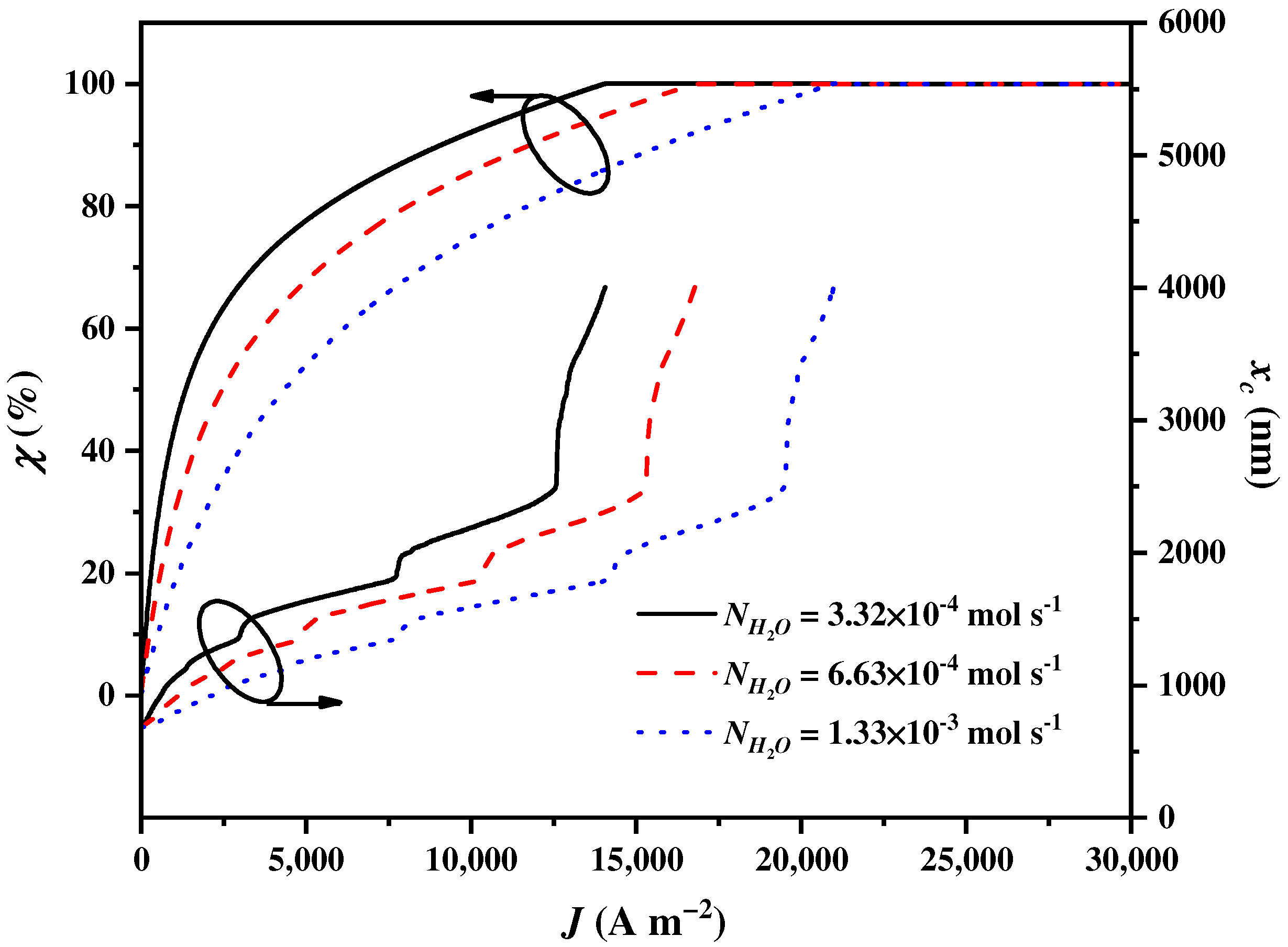
4.3. Influences of the SOEC Inlet Flow Rate of Water

The inlet flow rate of the water in the SOEC N H 2 O is a crucial operational condition that affects the amount of heat used to preheat the water, thereby affecting the electricity and heat requirements of the SOEC. This, in turn, impacts the balance parameter χ and the cut-off wavelength x c . As shown in Figure 6, χ increases to attain 100% and x c increases to the upmost wavelength with the increase in J . The growth rates of χ and x c decrease as N H 2 O increases. This phenomenon suggests that a larger N H 2 O increases the heat requirement of the SOEC. Consequently, more solar spectrums need to be assigned to the CSC by the CSSS for heat generation.

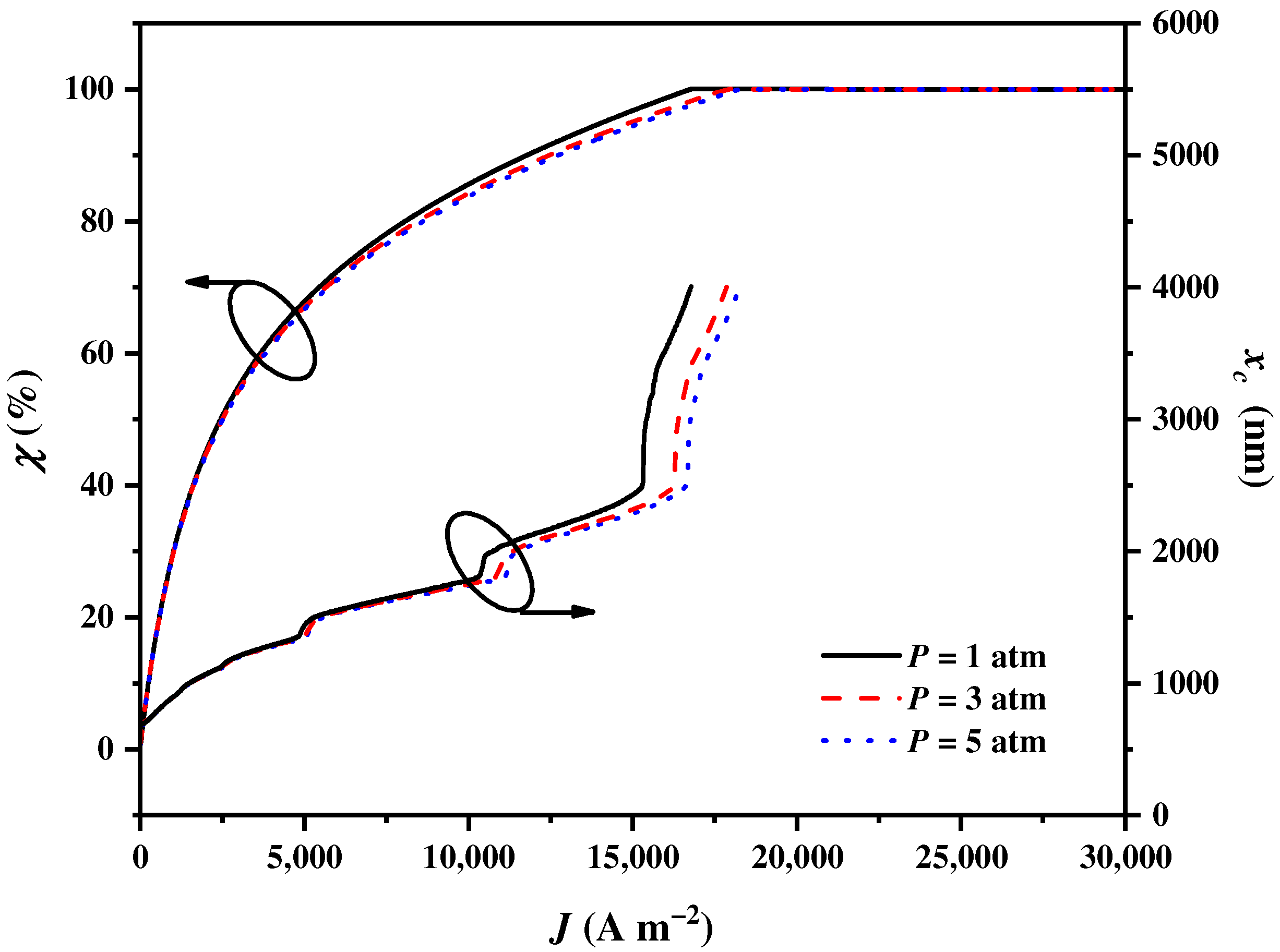
4.4. Influences of the SOEC Operating Pressure

The operating pressure of the SOEC P is another operating condition that affects the input voltage, thereby affecting the electricity and heat requirements of the SOEC. This, in turn, impacts the balance parameter χ and cut-off wavelength x c . As shown in Figure 7, χ increases to attain 100% and x c increases to the upmost wavelength with the increase in J . The growth rates of χ and x c for P = 1   atm are the largest, followed by those for P = 3   atm and P = 5   atm . The effects of the operating pressure on χ and x c first grow and then diminish as J gradually increases. This is because a higher P reduces the concentration overpotentials during the reaction process. Consequently, there is a reduction in the requirement for electricity, along with an increase in the requirement for heat. As a result, more solar spectrums need to be assigned to the CSC by the CSSS for heat generation. If the electricity consumption of the compressing reactants is considered, the impacts of the operating pressure are weakened.

4.5. Influences of the Effectiveness of Heat Exchangers

The effectiveness of the heat exchangers ε is an important parameter that affects the heat transfer within the hybrid system, thereby affecting the electricity and heat balance of the hybrid system. This, in turn, impacts the balance parameter χ and cut-off wavelength x c . As shown in Figure 8, χ non-linearly increases to attain 100% and x c increases to the upmost wavelength with the increase in J . The growth rates of χ and x c for ε = 0.8 are the largest, followed by those for ε = 0.7 and ε = 0.6 . From the thermodynamic perspective, a larger ε reduces the heat loss during heat transfer. In order to adapt the more efficient heat exchangers, more solar spectrums can be assigned to the CPV by the CSSS for electricity generation for higher hydrogen production efficiency.

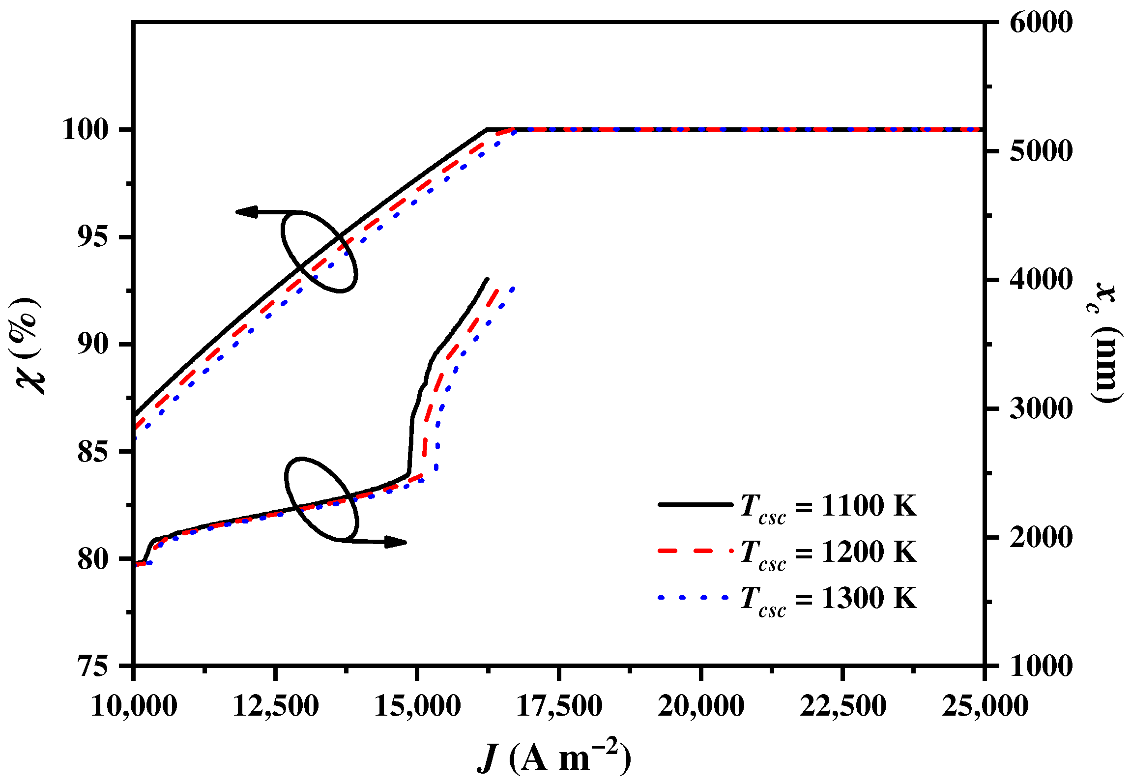
4.6. Influences of the CSC Operating Temperature

The operating temperature of the CSC T C S C affects the heat transfer from Q C S C to the SOEC or the heat exchangers, thereby influencing the balance parameter χ and the cut-off wavelength x c . As shown in Figure 9, χ increases to attain 100% and x c increases to the upmost wavelength with the increase in J . The growth rates of χ and x c for T C S C = 1100   K are the largest, followed by those for T C S C = 1200   K and T C S C = 1300   K . From the thermodynamic perspective, a higher T C S C increases the heat losses during heat transfer, and more solar spectrums need to be assigned to the CSC by the CSSS for heat generation.

4.7. Influences of the CPV Operating Temperature

The operating temperature of the CPV T C P V is an important operational condition that affects the CPV output power and then significantly impacts the cut-off wavelength x c . However, the T C P V of the CPV does not affect the balance parameter χ . This is because χ is determined by the exergy requirements of the SOEC. The x c alters to meet the electricity and heat demands of the SOEC under different CPV operating temperatures. As shown in Figure 10, x c increases to the upmost wavelength with the increase in J . The growth rates of x c for T C P V = 380   K are initially the largest, and then they gradually become the lowest as J increases, followed by those for T C P V = 370   K and T C P V = 360   K . However, x c sharply grows to the upmost wavelength when J approaches J S regardless of T C P V . The influence of T C P V on x c becomes insensitive as the sunlight wavelength increases. This is because short wavelengths have higher solar radiation, and long wavelengths have lower solar radiation. In addition, a higher T C P V decreases the output power and efficiency of CPV [83], and more solar spectrums should be assigned to the CPV by the CSSS for electricity generation.

4.8. Influences of the CPV Optical Concentration Ratio

The optical concentration ratio of the CPV C C P V is a pivotal design parameter that influences the performance of the CPV and subsequently affects the cut-off wavelength x c . A larger value of C C P V indicates that a higher amount of solar energy is incident upon the CPV per unit time, thereby contributing to the enhancement of the CPV performance. The C C P V does not affect the balance parameter χ , but x c alters to meet the electricity and heat demands of SOEC under different levels of C C P V . As shown in Figure 11, x c increases to the upmost wavelength with the increase in J . The growth rates of x c for C C P V = 7 are initially the largest, and then they gradually become the lowest as J increases, followed by those for C C P V = 6 and C C P V = 5 . However, x c sharply grows to the upmost wavelength when J approaches J S regardless of C C P V . When C C P V increases from 5 to 7, the available ranges of spectrums for splitting in the CSSS expand from 673 nm~infinity to 529 nm~infinity. However, the electricity generation efficiency of the CPV is much lower than the heat efficiency of the CSC during the energy conversion process [84,85]. With a higher C C P V in the CPV, more solar spectrums are assigned to the CPV by the CSSS for electricity generation.

4.9. Influences of the CPV Electric Current

The electric current of the CPV I C P V is the primary operating parameter that directly influences both the CPV performance and the output power, subsequently resulting in an impact on the cut-off wavelength x c . The I C P V of the CPV also does not affect the balance parameter χ , and x c alters to meet the electricity and heat demands of the SOEC under different CPV electric currents. As shown in Figure 12, x c increases to the upmost wavelength with the increase in J . The growth rate of x c for I C P V = 8   A is initially the largest, and then it gradually becomes the lowest as J increases, followed by those for I C P V = 10   A and I C P V = 12   A . The x c sharply grows to the upmost wavelength when J approaches J S regardless of I C P V . When the I C P V in the CPV increases from 8   A to 12   A , the available ranges of spectrums split by the CSSS narrow from 619 nm~infinity to 787 nm~infinity, but the power output of the CPV increases [84]. Therefore, with a higher I C P V in the CPV, more solar spectrums are assigned to the CSC by the CSSS for heat generation.

5. Conclusions

In this paper, a mathematical model coupling an SOEC to a CSSS was established to further understand how to effectively split the solar spectrums to the CPV for electricity generation and to the CSC for heat generation by the CSSS to ensure the normal operation and efficient hydrogen production of the SOEC. Based on the theories of electrochemistry and thermodynamics, the requirements of electricity and heat for the SOEC were predicted. Accordingly, the effects of the structural parameters and operational conditions on the electricity requirements and cut-off wavelength splitting solar spectrums by the CSSS were discussed. The anode-supported type, higher operating temperature, larger inlet flow rate of water, higher SOEC operating pressure, higher CSC operating temperature, and larger electric current of the CPV result in the assignment of more solar spectrums to the CSC by the CSSS for heat generation. However, the greater effectiveness of the heat exchangers, higher operating temperature, and larger optical concentration ratio of the CPV exhibit contrasting effects on the spectrum allocation. The research results provide theoretical guidance for the allocation of solar spectrums by the CSSS to the SOEC for hydrogen production.

Author Contributions

Conceptualization, H.Z.; Software, S.L.; Resources, J.Y.; Data curation, S.L.; Writing—original draft, S.L.; Writing—review & editing, H.Z.; Supervision, J.Y. and H.Z.; Funding acquisition, J.Y. All authors have read and agreed to the published version of the manuscript.

Funding

This work is supported by the National Key Research and Development Project of China (2018YFB1502204) and the Ningbo major special projects of the Plan “Science and Technology Innovation 2025” (2018B10048).

Data Availability Statement

The original contributions presented in the study are included in the article, further inquiries can be directed to the corresponding author.

Conflicts of Interest

The authors declare no conflict of interest.

Nomenclature

A Diode ideality factor
A C Area of the concentrator ( m 2 )
A C P V Effective area of the CPV ( m 2 )
A S O E C Effective surface area of the SOEC ( m 2 )
B g Permeability ( m 2   Pa 1   s 1 )
C C P V Optical concentration ratio of CPV
C p , m Molar heat capacities of reactant/products ( J   mol 1   K 1 )
D H 2 O e f f Effective diffusion coefficient of H 2 O ( m   s 1 )
D N I A M 1.5 ( λ ) Solar irradiance of AM1.5 direct spectrums ( W   m 2 )
E A M 1.5 ( λ ) Solar irradiance of AM1.5 direct spectrum at λ ( W   m 2 )
E Equilibrium potential ( V )
E 0 Standard potential ( V )
E a c t Activation energy ( J   mol 1 )
E g Band-gap energy of semiconductor materials ( eV )
F Faraday constant ( C   mol 1 )
G Gibbs energy ( J   mol 1 )
G C P V Solar radiation ( W   m 2 )
G r Reference solar radiation ( W   m 2 )
H Enthalpy ( J   mol 1 )
I Electric current through the SOEC ( A )
I 0 Diode reverse current ( A )
I C P V Output electric current of the CPV ( A )
I L Photocurrent of the CPV ( A )
I r Reverse saturation current at reference temperature ( A )
I S C Short-circuit current of the CPV at reference temperature and solar radiation ( A )
J Current density ( A   m 2 )
J 0 Exchange current density ( A   m 2 )
K b Boltzmann constant ( J   K 1 )
K s c Short-circuit current temperature coefficient
L Thickness ( m )
L v Latent heat of water under 1 bar ( J   mol 1 )
n Number of moles
n p Number of cells in parallel
n s Number of cells in series
P C P V Power output of CPV ( W )
P H 2 Partial pressure of hydrogen ( bar )
P H 2 O Partial pressure of steam ( bar )
P O 2 Partial pressure of oxygen ( bar )
P S O E C Input electric power of the SOEC ( W )
q Charge of an electron ( C )
Q Heat ( J   mol 1 )
Q C P V Energy received by the CPV ( W   m 2 )
Q C S C Energy received by the CSC ( W   m 2 )
Q H 2 O Heat required for heating water per unit time ( W )
Q S O E C Heat required for the SOSE per unit time ( W )
Q S O L A R Total solar radiation energy ( W   m 2 )
R Gas constant ( J   mol 1   K 1 )
R S Intrinsic series resistance of the CPV ( Ω )
S Entropy ( J   mol 1   K 1 )
T Operating temperature of SOEC ( K )
T 0 Environment temperature ( K )
T b Boiling temperature of water ( K )
T C P V operating temperature of CPV ( K )
T C S C Temperature of the heat supplied by CSC ( K )
T s u n Surface temperature of the sun ( K )
T X Temperature of the heat supplied by the CSC or the SOEC ( K )
V Potential ( V )
V C P V Output electric voltage of the CPV ( V )
x c Cut-off wavelength ( nm )
X c a l , i Modeling results
X e x p , i Experimental data
Acronyms
CPVConcentrated photovoltaic
CSCConcentrating solar collector
CSSSConcentrating solar spectrums splitter
SMFSteam molar fraction
SOECSolid oxide electrolysis cell
Greek symbols
χ Balance parameter
δ Rate of entropy ( J   mol 1   s 1 )
γ Pre-exponential factors ( A   m 2 )
η C P V Energy efficiency
η o p t Optical efficiency of the concentrator and filter
λ Wavelength of sunlight ( nm )
μ Dynamic viscosity ( μ P )
ν Rate of electrochemical reaction ( mol   s 1 )
σ Electric conductivity ( Ω 1   m 1 )
ψ C P V Exergy efficiency
Superscripts and subscripts
a Anode
a c t Activation
c Cathode
c o n Concentration
e Electrolyte
o h m Ohmic

References

  1. Acar, C.; Dincer, I. The potential role of hydrogen as a sustainable transportation fuel to combat global warming. Int. J. Hydrogen Energy 2020, 45, 3396–3406. [Google Scholar] [CrossRef]
  2. Asongu, S.A.; Agboola, M.O.; Alola, A.A.; Bekun, F.V. The criticality of growth, urbanization, electricity and fossil fuel consumption to environment sustainability in Africa. Sci. Total Environ. 2020, 712, 136376. [Google Scholar] [CrossRef] [PubMed]
  3. Lü, X.; Wu, Y.; Lian, J.; Zhang, Y.; Chen, C.; Wang, P.; Meng, L. Energy management of hybrid electric vehicles: A review of energy optimization of fuel cell hybrid power system based on genetic algorithm. Energy Convers. Manag. 2020, 205, 112474. [Google Scholar] [CrossRef]
  4. Cetinkaya, E.; Dincer, I.; Naterer, G.F. Life cycle assessment of various hydrogen production methods. Int. J. Hydrogen Energy 2012, 37, 2071–2080. [Google Scholar] [CrossRef]
  5. Balat, M. Potential importance of hydrogen as a future solution to environmental and transportation problems. Int. J. Hydrogen Energy 2008, 33, 4013–4029. [Google Scholar] [CrossRef]
  6. Muradov, N.Z.; Veziroğlu, T.N. “Green” path from fossil-based to hydrogen economy: An overview of carbon-neutral technologies. Int. J. Hydrogen Energy 2008, 33, 6804–6839. [Google Scholar] [CrossRef]
  7. Huang, H.; Lin, M. Dynamic behavior of solar thermochemical reactors for fuel generation: Modeling and control strategies. Energy Convers. Manag. 2022, 270, 116232. [Google Scholar] [CrossRef]
  8. Caliskan, H.; Dincer, I.; Hepbasli, A. Exergoeconomic and environmental impact analyses of a renewable energy based hydrogen production system. Int. J. Hydrogen Energy 2013, 38, 6104–6111. [Google Scholar] [CrossRef]
  9. Balthasar, W. Hydrogen production and technology: Today, tomorrow and beyond. Int. J. Hydrogen Energy 1984, 9, 649–668. [Google Scholar] [CrossRef]
  10. Lakhera, S.K.; Rajan, A.; Rugma, T.; Bernaurdshaw, N. A review on particulate photocatalytic hydrogen production system: Progress made in achieving high energy conversion efficiency and key challenges ahead. Renew. Sustain. Energy Rev. 2021, 152, 111694. [Google Scholar] [CrossRef]
  11. Erdemir, D.; Dincer, I. Development of solar-driven charging station integrated with hydrogen as an energy storage option. Energy Convers. Manag. 2022, 257, 115436. [Google Scholar] [CrossRef]
  12. Li, Y.; Wei, X.; Chen, L.; Shi, J. Electrocatalytic hydrogen production trilogy. Angew. Chem. Int. Ed. 2021, 60, 19550–19571. [Google Scholar] [CrossRef] [PubMed]
  13. Tong, W.; Forster, M.; Dionigi, F.; Dresp, S.; Sadeghi Erami, R.; Strasser, P.; Cowan, A.J.; Farràs, P. Electrolysis of low-grade and saline surface water. Nat. Energy 2020, 5, 367–377. [Google Scholar] [CrossRef]
  14. Kelly, N.A.; Gibson, T.L. Solar energy concentrating reactors for hydrogen production by photoelectrochemical water splitting. Int. J. Hydrogen Energy 2008, 33, 6420–6431. [Google Scholar] [CrossRef]
  15. Ngoh, S.K.; Njomo, D. An overview of hydrogen gas production from solar energy. Renew. Sustain. Energy Rev. 2012, 16, 6782–6792. [Google Scholar] [CrossRef]
  16. Satyapal, S.; Petrovic, J.; Read, C.; Thomas, G.; Ordaz, G. The US Department of Energy’s National Hydrogen Storage Project: Progress towards meeting hydrogen-powered vehicle requirements. Catal. Today 2007, 120, 246–256. [Google Scholar] [CrossRef]
  17. Udagawa, J.; Aguiar, P.; Brandon, N. Hydrogen production through steam electrolysis: Model-based steady state performance of a cathode-supported intermediate temperature solid oxide electrolysis cell. J. Power Sources 2007, 166, 127–136. [Google Scholar] [CrossRef]
  18. Demin, A.; Gorbova, E.; Tsiakaras, P. High temperature electrolyzer based on solid oxide co-ionic electrolyte: A theoretical model. J. Power Sources 2007, 171, 205–211. [Google Scholar] [CrossRef]
  19. Herring, J.S.; O’Brien, J.E.; Stoots, C.M.; Hawkes, G.; Hartvigsen, J.J.; Shahnam, M. Progress in high-temperature electrolysis for hydrogen production using planar SOFC technology. Int. J. Hydrogen Energy 2007, 32, 440–450. [Google Scholar] [CrossRef]
  20. Arashi, H.; Naito, H.; Miura, H. Hydrogen production from high-temperature steam electrolysis using solar energy. Int. J. Hydrogen Energy 1991, 16, 603–608. [Google Scholar] [CrossRef]
  21. Maka, A.O.; O’Donovan, T.S. A review of thermal load and performance characterisation of a high concentrating photovoltaic (HCPV) solar receiver assembly. Sol. Energy 2020, 206, 35–51. [Google Scholar] [CrossRef]
  22. Liu, J.; Liu, X.; Xin, J.; Zhang, Y.; Wen, L.; Liang, Q.; Miao, Z. Dual Function of the Third Component in Ternary Organic Solar Cells: Broaden the Spectrum and Optimize the Morphology. Small 2024, 2308863. [Google Scholar] [CrossRef]
  23. Zou, Y.; Qin, C.; Liu, H.; Zhang, B.; Wu, X. Concentrating photovoltaic systems: A review of temperature effects and components. J. Therm. Anal. Calorim. 2024, 149, 1301–1329. [Google Scholar] [CrossRef]
  24. Rajendran, D.R.; Ganapathy Sundaram, E.; Jawahar, P.; Sivakumar, V.; Mahian, O.; Bellos, E. Review on influencing parameters in the performance of concentrated solar power collector based on materials, heat transfer fluids and design. J. Therm. Anal. Calorim. 2020, 140, 33–51. [Google Scholar] [CrossRef]
  25. Mohammadi, A.; Mehrpooya, M. Techno-economic analysis of hydrogen production by solid oxide electrolyzer coupled with dish collector. Energy Convers. Manag. 2018, 173, 167–178. [Google Scholar] [CrossRef]
  26. Imenes, A.; Mills, D. Spectral beam splitting technology for increased conversion efficiency in solar concentrating systems: A review. Sol. Energy Mater. Sol. Cells 2004, 84, 19–69. [Google Scholar] [CrossRef]
  27. Joshi, A.S.; Dincer, I.; Reddy, B.V. Solar hydrogen production: A comparative performance assessment. Int. J. Hydrogen Energy 2011, 36, 11246–11257. [Google Scholar] [CrossRef]
  28. Edwards, J.; Badwal, S.; Duffy, G.; Lasich, J.; Ganakas, G. The application of solid state ionic technology for novel methods of energy generation and supply. Solid State Ion. 2002, 152, 843–852. [Google Scholar] [CrossRef]
  29. Mittelman, G.; Kribus, A. Innovative Solar Spectral Beam Splitting Concepts: Alternative Fuels Production. In Proceedings of the 35th European Photovoltaic Solar Energy Conference and Exhibition, Brussels, Belgium, 24–28 September 2018; pp. 1895–1898. [Google Scholar]
  30. Daneshpour, R.; Mehrpooya, M. Design and optimization of a combined solar thermophotovoltaic power generation and solid oxide electrolyser for hydrogen production. Energy Convers. Manag. 2018, 176, 274–286. [Google Scholar] [CrossRef]
  31. Kaleibari, S.S.; Yanping, Z.; Abanades, S. Solar-driven high temperature hydrogen production via integrated spectrally split concentrated photovoltaics (SSCPV) and solar power tower. Int. J. Hydrogen Energy 2019, 44, 2519–2532. [Google Scholar] [CrossRef]
  32. Gopalan, S.; Mosleh, M.; Hartvigsen, J.J.; McConnell, R.D. Analysis of self-sustaining recuperative solid oxide electrolysis systems. J. Power Sources 2008, 185, 1328–1333. [Google Scholar] [CrossRef]
  33. Lin, M.; Haussener, S. Techno-economic modeling and optimization of solar-driven high-temperature electrolysis systems. Sol. Energy 2017, 155, 1389–1402. [Google Scholar] [CrossRef]
  34. Thompson, J.R.; McConnell, R.D.; Mosleh, M. Cost Analysis of a Concentrator Photovoltaic Hydrogen Production System; National Renewable Energy Lab. (NREL): Golden, CO, USA, 2005.
  35. Mottaghizadeh, P.; Fardadi, M.; Jabbari, F.; Brouwer, J. Dynamics and control of a thermally self-sustaining energy storage system using integrated solid oxide cells for an islanded building. Int. J. Hydrogen Energy 2021, 46, 24891–24908. [Google Scholar] [CrossRef]
  36. Udagawa, J.; Aguiar, P.; Brandon, N. Hydrogen production through steam electrolysis: Control strategies for a cathode-supported intermediate temperature solid oxide electrolysis cell. J. Power Sources 2008, 180, 354–364. [Google Scholar] [CrossRef]
  37. Mahapatra, M.; Lu, K. Glass-based seals for solid oxide fuel and electrolyzer cells—A review. Mater. Sci. Eng. R Rep. 2010, 67, 65–85. [Google Scholar] [CrossRef]
  38. Liu, J.; Wang, J.; Tang, Y.; Jin, J.; Li, W. Solar photovoltaic–thermal hydrogen production system based on full-spectrum utilization. J. Clean. Prod. 2023, 430, 139340. [Google Scholar] [CrossRef]
  39. Baniasadi, E. Concurrent hydrogen and water production from brine water based on solar spectrum splitting: Process design and thermoeconomic analysis. Renew. Energy 2017, 102, 50–64. [Google Scholar] [CrossRef]
  40. Fang, J.; Yang, M.; Cui, L.; Yi, X.; Huo, H.; Wen, Z.; Liu, X. Efficient hydrogen production system with complementary utilization of methane and full-spectrum solar energy. Energy Convers. Manag. 2023, 283, 116951. [Google Scholar] [CrossRef]
  41. Zhang, H.; Lin, G.; Chen, J. Evaluation and calculation on the efficiency of a water electrolysis system for hydrogen production. Int. J. Hydrogen Energy 2010, 35, 10851–10858. [Google Scholar] [CrossRef]
  42. Guo, X.-Z.; Zhang, Y.-D.; Qin, D.; Luo, Y.-H.; Li, D.-M.; Pang, Y.-T.; Meng, Q.-B. Hybrid tandem solar cell for concurrently converting light and heat energy with utilization of full solar spectrum. J. Power Sources 2010, 195, 7684–7690. [Google Scholar] [CrossRef]
  43. Wang, C.; Chen, M.; Liu, M.; Yan, J. Dynamic modeling and parameter analysis study on reversible solid oxide cells during mode switching transient processes. Appl. Energy 2020, 263, 114601. [Google Scholar] [CrossRef]
  44. Zhao, Y.; Lu, M.; Li, Y.; Ge, M.; Xie, L.; Liu, L. Characteristics analysis of an exhaust thermoelectric generator system with heat transfer fluid circulation. Appl. Energy 2021, 304, 117896. [Google Scholar] [CrossRef]
  45. Akikur, R.; Saidur, R.; Ping, H.; Ullah, K. Performance analysis of a co-generation system using solar energy and SOFC technology. Energy Convers. Manag. 2014, 79, 415–430. [Google Scholar] [CrossRef]
  46. Özdemir, A.; Gamze, G. A comprehensive comparative energy and exergy analysis in solar based hydrogen production systems. Int. J. Hydrogen Energy 2022, 47, 12189–12203. [Google Scholar] [CrossRef]
  47. Yadav, D.; Banerjee, R. Economic assessment of hydrogen production from solar driven high-temperature steam electrolysis process. J. Clean. Prod. 2018, 183, 1131–1155. [Google Scholar] [CrossRef]
  48. Taheri, M.H.; Khani, L.; Mohammadpourfard, M.; Aminfar, H.; Akkurt, G.G. Multi-objective optimization of a novel supercritical CO2 cycle-based combined cycle for solar power tower plants integrated with SOFC and LNG cold energy and regasification. Int. J. Energy Res. 2022, 46, 12082–12107. [Google Scholar] [CrossRef]
  49. Udagawa, J.; Aguiar, P.; Brandon, N. Hydrogen production through steam electrolysis: Model-based dynamic behaviour of a cathode-supported intermediate temperature solid oxide electrolysis cell. J. Power Sources 2008, 180, 46–55. [Google Scholar] [CrossRef]
  50. Ni, M.; Leung, M.K.H.; Leung, D.Y.C. A modeling study on concentration overpotentials of a reversible solid oxide fuel cell. J. Power Sources 2006, 163, 460–466. [Google Scholar] [CrossRef]
  51. Iwahara, H. High temperature proton conducting oxides and their applications to solid electrolyte fuel cells and steam electrolyzer for hydrogen production. Solid State Ion. 1988, 28, 573–578. [Google Scholar] [CrossRef]
  52. Hino, R.; Haga, K.; Aita, H.; Sekita, K. 38. R&D on hydrogen production by high-temperature electrolysis of steam. Nucl. Eng. Des. 2004, 233, 363–375. [Google Scholar]
  53. Shin, Y.; Park, W.; Chang, J.; Park, J. Evaluation of the high temperature electrolysis of steam to produce hydrogen. Int. J. Hydrogen Energy 2007, 32, 1486–1491. [Google Scholar] [CrossRef]
  54. Ni, M.; Leung, M.K.; Leung, D.Y. An electrochemical model of a solid oxide steam electrolyzer for hydrogen production. Chem. Eng. Technol. Ind. Chem.-Plant Equip.-Process Eng.-Biotechnol. 2006, 29, 636–642. [Google Scholar] [CrossRef]
  55. Ni, M.; Leung, M.K.; Leung, D.Y. Energy and exergy analysis of hydrogen production by solid oxide steam electrolyzer plant. Int. J. Hydrogen Energy 2007, 32, 4648–4660. [Google Scholar] [CrossRef]
  56. Zhao, Y.; Sadhukhan, J.; Lanzini, A.; Brandon, N.; Shah, N. Optimal integration strategies for a syngas fuelled SOFC and gas turbine hybrid. J. Power Sources 2011, 196, 9516–9527. [Google Scholar] [CrossRef]
  57. Nam, J.H.; Jeon, D.H. A comprehensive micro-scale model for transport and reaction in intermediate temperature solid oxide fuel cells. Electrochim. Acta 2006, 51, 3446–3460. [Google Scholar] [CrossRef]
  58. Todd, B.; Young, J. Thermodynamic and transport properties of gases for use in solid oxide fuel cell modelling. J. Power Sources 2002, 110, 186–200. [Google Scholar] [CrossRef]
  59. Yakabe, H.; Hishinuma, M.; Uratani, M.; Matsuzaki, Y.; Yasuda, I. Evaluation and modeling of performance of anode-supported solid oxide fuel cell. J. Power Sources 2000, 86, 423–431. [Google Scholar] [CrossRef]
  60. Cai, Q.; Luna-Ortiz, E.; Adjiman, C.; Brandon, N. The Effects of Operating Conditions on the Performance of a Solid Oxide Steam Electrolyser: A Model-Based Study. Fuel Cells 2010, 10, 1114–1128. [Google Scholar] [CrossRef]
  61. Cai, Q.; Adjiman, C.S.; Brandon, N.P. Maximizing Hydrogen Production of A Solid Oxide Electrolyser Cell. In Proceedings of the 2012 International Conference on Clean and Green Energy, Singapore, 5–7 January 2012; pp. 72–77. [Google Scholar]
  62. Zhao, Y.; Ou, C.; Chen, J. A new analytical approach to model and evaluate the performance of a class of irreversible fuel cells. Int. J. Hydrogen Energy 2008, 33, 4161–4170. [Google Scholar] [CrossRef]
  63. Watowich, S.J.; Berry, R.S. Optimal current paths for model electrochemical systems. J. Phys. Chem. 1986, 90, 4624–4631. [Google Scholar] [CrossRef]
  64. Ni, M.; Leung, M.K.; Leung, D.Y. Technological development of hydrogen production by solid oxide electrolyzer cell (SOEC). Int. J. Hydrogen Energy 2008, 33, 2337–2354. [Google Scholar] [CrossRef]
  65. Doenitz, W.; Schmidberger, R.; Steinheil, E.; Streicher, R. Hydrogen production by high temperature electrolysis of water vapour. Int. J. Hydrogen Energy 1980, 5, 55–63. [Google Scholar] [CrossRef]
  66. Li, W.; Jin, J.; Wang, H.; Wei, X.; Ling, Y.; Hao, Y.; Pei, G.; Jin, H. Full-spectrum solar energy utilization integrating spectral splitting, photovoltaics and methane reforming. Energy Convers. Manag. 2018, 173, 602–612. [Google Scholar] [CrossRef]
  67. Wu, H.; Zhou, Z.; Shan, S. Optimal design principle of a cascading solar photovoltaic system with concentrating spectrum splitting and reshaping. Renew. Energy 2022, 197, 197–210. [Google Scholar] [CrossRef]
  68. Liao, T.; Lin, B.; Yang, Z. Performance characteristics of a low concentrated photovoltaic–thermoelectric hybrid power generation device. Int. J. Therm. Sci. 2014, 77, 158–164. [Google Scholar] [CrossRef]
  69. Le Pierrès, N.; Cosnier, M.; Luo, L.; Fraisse, G. Coupling of thermoelectric modules with a photovoltaic panel for air pre-heating and pre-cooling application; an annual simulation. Int. J. Energy Res. 2008, 32, 1316–1328. [Google Scholar] [CrossRef]
  70. Zhao, Q.; Zhang, H.; Hu, Z. Hybridizing photovoltaic cell with direct contact membrane distillation for electricity and freshwater cogeneration: Concept and performance evaluation. Desalination 2020, 496, 114701. [Google Scholar] [CrossRef]
  71. Ma, L.; Zhao, Q.; Zhang, H. Performance analysis of a new hybrid system composed of a concentrated photovoltaic cell and a two-stage thermoelectric generator. Sustain. Energy Grids Netw. 2021, 27, 100481. [Google Scholar] [CrossRef]
  72. Kalogirou, S.A. Solar thermal collectors and applications. Progress Energy Combust. Sci. 2004, 30, 231–295. [Google Scholar] [CrossRef]
  73. Basha, C.H.; Rani, C.; Odofin, S. A review on non-isolated inductor coupled DC-DC converter for photovoltaic grid-connected applications. Int. J. Renew. Energy Res. IJRER 2017, 7, 1570–1585. [Google Scholar]
  74. Harrag, A.; Titraoui, A.; Bahri, H.; Messalti, S. Photovoltaic pumping system-Comparative study analysis between direct and indirect coupling mode. AIP Conf. Proc. 2017, 1814, 020002. [Google Scholar]
  75. Dahbi, S.; Aboutni, R.; Aziz, A.; Benazzi, N.; Elhafyani, M.; Kassmi, K. Optimised hydrogen production by a photovoltaic-electrolysis system DC/DC converter and water flow controller. Int. J. Hydrogen Energy 2016, 41, 20858–20866. [Google Scholar] [CrossRef]
  76. Kelly, N.A.; Gibson, T.L.; Ouwerkerk, D.B. Generation of high-pressure hydrogen for fuel cell electric vehicles using photovoltaic-powered water electrolysis. Int. J. Hydrogen Energy 2011, 36, 15803–15825. [Google Scholar] [CrossRef]
  77. Kelly, N.A.; Gibson, T.L.; Cai, M.; Spearot, J.A.; Ouwerkerk, D.B. Development of a renewable hydrogen economy: Optimization of existing technologies. Int. J. Hydrogen Energy 2010, 35, 892–899. [Google Scholar] [CrossRef]
  78. Zhang, H.; Su, S.; Chen, X.; Lin, G.; Chen, J. Configuration design and performance optimum analysis of a solar-driven high temperature steam electrolysis system for hydrogen production. Int. J. Hydrogen Energy 2013, 38, 4298–4307. [Google Scholar] [CrossRef]
  79. Ni, M.; Leung, M.K.H.; Leung, D.Y.C. Parametric study of solid oxide steam electrolyzer for hydrogen production. Int. J. Hydrogen Energy 2007, 32, 2305–2313. [Google Scholar] [CrossRef]
  80. Momma, A.; Kato, T.; Kaga, Y.; Nagata, S. Polarization behavior of high temperature solid oxide electrolysis cells (SOEC). J. Ceram. Soc. Jpn. 1997, 105, 369–373. [Google Scholar] [CrossRef]
  81. Kong, C.; Xu, Z.; Yao, Q. Outdoor performance of a low-concentrated photovoltaic–thermal hybrid system with crystalline silicon solar cells. Appl. Energy 2013, 112, 618–625. [Google Scholar] [CrossRef]
  82. Wu, S.-Y.; Zhong, Z.-H.; Xiao, L.; Chen, Z.-L. Performance analysis on a novel photovoltaic-hydrophilic modified tubular seawater desalination (PV-HMTSD) system. Desalination 2021, 499, 114829. [Google Scholar] [CrossRef]
  83. Mahmoudinezhad, S.; Rezania, A.; Rosendahl, L.A. Behavior of hybrid concentrated photovoltaic-thermoelectric generator under variable solar radiation. Energy Convers. Manag. 2018, 164, 443–452. [Google Scholar] [CrossRef]
  84. Ma, L.; Zhao, Q.; Zhang, H.; Hou, S.; Zhao, J.; Wang, F.; Zhang, C.; Miao, H.; Yuan, J. Performance analysis of a concentrated photovoltaic cell-elastocaloric cooler hybrid system for power and cooling cogeneration. Energy 2022, 239, 122290. [Google Scholar] [CrossRef]
  85. Joshi, A.S.; Dincer, I.; Reddy, B.V. Effects of various parameters on energy and exergy efficiencies of a solar thermal hydrogen production system. Int. J. Hydrogen Energy 2016, 41, 7997–8007. [Google Scholar] [CrossRef]
Figure 1. Schematic diagram of a CSSS-powered SOEC for hydrogen production.
Energies 17 02067 g001
Figure 2. (a) The modeling and the experimental results of the potential of an SOEC V varying with a steam molar fraction (SMF). The experimental data are from [80]. (b) The modeling and the experimental results of the CPV energy efficiency η C P V varying with the operating temperature T C P V . The experimental data are from [81].
Energies 17 02067 g002
Figure 3. Flow chart of the CSSS-SOEC hybrid system model solution.
Energies 17 02067 g003
Figure 4. The balance parameter χ and the cut-off wavelength x c varying with the current density J using different SOEC support types.
Energies 17 02067 g004
Figure 5. The balance parameter χ and the cut-off wavelength x c varying with the current density J under different SOEC operating temperatures SOEC T .
Energies 17 02067 g005
Figure 6. The balance parameter χ and the cut-off wavelength x c varying with the current density J under different the inlet flow rates of water in the SOEC N H 2 O .
Energies 17 02067 g006
Figure 7. The balance parameter χ and the cut-off wavelength x c varying with the current density J under different SOEC operating pressures P .
Energies 17 02067 g007
Figure 8. The balance parameter χ and the cut-off wavelength x c varying with the current density J under different levels of effectiveness of heat exchangers ε .
Energies 17 02067 g008
Figure 9. The balance parameter χ and the cut-off wavelength x c varying with the current density J under different CSC temperatures T C S C .
Energies 17 02067 g009
Figure 10. The cut-off wavelength x c varying with the current density J under different CPV operating temperatures T C P V .
Energies 17 02067 g010
Figure 11. The cut-off wavelength x c varying with the current density J under the different optical concentration ratios in the CPV C C P V .
Energies 17 02067 g011
Figure 12. The cut-off wavelength x c varying with the current density J under different electric currents in the CPV I C P V .
Energies 17 02067 g012
Table 1. Parameters used in SOEC modeling.
ParameterSymbolValue
Operating pressure P 1.0   bar
Partial pressure of hydrogen P H 2 0.4   bar
Partial pressure of steam P H 2 O 0.6   bar
Partial pressure of oxygen P O 2 1   bar
Preexponential factor for anode exchanger current density γ a 2.051 × 10 9   A   m 2
Preexponential factor for cathode exchanger current density γ c 1.344 × 10 10   A   m 2
Activation energy for anode E a c t , a 1.2 × 10 5   J   mol 1
Activation energy for cathode E a c t , c 1.0 × 10 5   J   mol 1
Electrode porosity ω 0.48
Electrode tortuosity ξ 5.4
Average pore radius r 1.07 × 10 5   m
Electrolyte thickness L e 5.0 × 10 5   m
Electrolyte ionic conductivity σ e 3.34 × 10 4 exp   ( 1.03 × 10 4 T 1 )   ( Ω · m ) 1
Cathode thickness L c 5.0 × 10 5   m
Cathode electric conductivity σ c 8.0 × 10 4   ( Ω · m ) 1
Anode thickness L a 5.0 × 10 4   m
Anode electric conductivity σ a 8.4 × 10 3   ( Ω · m ) 1
Efficiency of the heat exchangers ε 0.7
Operating temperature T 973   1073   1173   K
Temperature of the CSC T C S C 1300   K
Temperature of the environment T 0 298   K
Flow rate of H 2 O at SOEC inlet N H 2 O ,   i n 6.63 × 10 4   mol   s 1
Area of single-cell bipolar plates A S O E C 6.4 × 10 3   m 2
Table 2. Parameters used in the CPV modeling.
ParameterSymbolValue
Short-circuit current I S C 4.8   A
Diode ideality factor A 1.5
Short-circuit current temperature coefficient K S C 2.06 × 10 3   A   K 1
Reverse saturation current at reference temperature I r 0.118 × 10 6   A
Area of CPV A C P V 0.6   m 2
Number of strings in parallel n P 1
Number of cells in series n S 36
Intrinsic series resistance of the CPV R S 1.8 × 10 3   Ω
Reference temperature of CPV T 0 298   K
Reference solar irradiation G r 900   W   m 2
Electric current I C P V 10   A
Optical concentration ratio C C P V 5
Operating temperature of CPV T C P V 360   K
Surface temperature of the sun T s u n 5700   K
Elementary electron charge q 1.60218 × 10 19   C
Boltzmann constant K b 1.38066 × 10 23   J   K 1
Disclaimer/Publisher’s Note: The statements, opinions and data contained in all publications are solely those of the individual author(s) and contributor(s) and not of MDPI and/or the editor(s). MDPI and/or the editor(s) disclaim responsibility for any injury to people or property resulting from any ideas, methods, instructions or products referred to in the content.

