
Formulation and Characterization of Chitosan-Based Mixed-Matrix Scaffold for Tissue Engineering


1
Physics Department, University of Coimbra, Centre for Physics of the University of Coimbra (CFisUC), Polo I, Rua Larga, 3004-516 Coimbra, Portugal
2
Department of Chemical Engineering, University of Coimbra, Chemical Engineering and Renewable Resources for Sustainability (CERES), 3030-790 Coimbra, Portugal
*
Author to whom correspondence should be addressed.
Macromol 2024, 4(2), 253-268; https://0-doi-org.brum.beds.ac.uk/10.3390/macromol4020014
Submission received: 5 March 2024
/
Revised: 13 April 2024
/
Accepted: 17 April 2024
/
Published: 26 April 2024
Abstract
:The use of scaffolds, three-dimensional porous, biodegradable and biocompatible structures, that can be produced from natural polymers, synthetics, ceramics and metals is crucial in the tissue engineering field. Chitosan is a polysaccharide of natural origin, found in the exoskeleton of marine arthropods and in the cell wall of fungi, with enormous popularity in the production of three-dimensional materials for Tissue Engineering, in particular bone repair. This polymer has several advantages in the production of these structures in bone regeneration and repair: biodegradability, biocompatibility, non-toxicity and antimicrobial properties. This study aimed to prepare porous scaffolds, for bone repair of degenerative diseases in the spine with better performance and less secondary effects, based on chitosan and another biopolymer (sodium alginate) with the incorporation of calcium phosphates (hydroxyapatite and β-tricalcium phosphate), for tissue engineering application. The obtained scaffolds were object of a detailed characterization, namely with regard to their porosity through the ethanol method, degradation, positron annihilation spectroscopy (PAS), mechanical properties, scanning electronic microscope (SEM), thermal stability through thermogravimetric analysis (TGA), chemical composition through X-ray diffraction (XRD) and Fourier transform infrared spectroscopy (FTIR). The results obtained showed that the different scaffolds presented pores able to support osteoid matrix growth. The crosslinking of scaffolds was also evaluated and resulted in pores with smaller dimensions and higher regularity in the chitosan-sodium alginate polymer without calcium phosphate scaffold. It was also possible to observe the effect of inorganics on mixed-matrix scaffolds, both morphologically and chemically. These scaffolds showed promising results in terms of mechanical and chemical properties, along with promising porosity for tissue regeneration applications.
1. Introduction
The increase in human life expectancy and the problems that are associated with it, have led to the investigation of innovative medical devices in the Tissue Engineering field. However, the natural environment of the bone tissue, cartilage, skin, among others, is very complex to be recreated and there is still plenty of room for improvement. For example, degenerative diseases in the spine are frequent and difficult to treat, causing low back pain and sciatica, which radiate to the lower limbs. Moreover, due to bone aging, a decrease in total bone mass or low osteoblastic activity may occur, leading to fractures or delays in bone formation. The WHO estimates that 80–90% of the population is affected by degenerative diseases in the spine [1] mainly in the low back. Clinically, in addition to conservative treatments, surgical intervention is preferred, since it immediately relieves compression, corrects alignments and improves spine stability. Arthrodesis is a surgical method that consists in the permanent fusion of two or more vertebrae to eliminate local painful movements and/or replace the degenerated intervertebral disc. It is usually performed with the addition of bone grafts, intra-spinous threads or placement of lumbar plates between the vertebrae [2]. Currently, several products commercialized for the fusion of lumbar vertebrae are mainly based on silicates [3] with calcium phosphates.
Chitosan (CT) is one of the polysaccharides mostly used in bone defects applications due to its properties, such as biocompatibility, non-toxicicity, biodegrability, bacteriostatic properties and ability to facilitate the regenerative processes in wound healing [4,5]. Chitosan is also a polyelectrolyte polysaccharide that possesses positive charge density, which can promote interactions with negative polymers, in particular sodium alginate (SA) [6,7]. Therefore, CT and SA can form a polyelectrolyte complex, that is mainly driven by an electrostatic mechanism. In acid environment, the protonated amine groups of chitosan interact with the ionized carboxyl groups of sodium alginate. Despite the advantages of this complex, it fails, for some applications, in the sense that it lacks rigidity and for that purpose crosslinking is used and/or an inorganic component is sometime added to the formulation.
Crosslinking methods are very important on the development of scaffolds in tissue engineering. The main goal of this technology is to improve biomechanical properties of the scaffolds by the formation of a firm network in the polymeric matrix. In general, crosslinking is used to enhance the mechanical properties and chemical resistance of the material, the changes in biomechanical properties are a consequence of the changes in mechanical properties. There are many methods of crosslinking, being the most used the physical and chemical crosslinkers for this end. The chemical crosslinking has the advantage to form stronger bonds between the two functional groups. An ideal crosslinker should improve mechanical, degradation and biological properties, but not lead to cytotoxic effects [8,9]. Several crosslinkers are used when chitosan is the polymer, such as glutaraldehyde, glyoxal, epichlorohydrin, tetraethyl orthosilicate, among others. Glyoxal was the chemical crosslinker chosen for this work. It is a reactive α-oxoaldehyde whose has two aldehyde groups [10] that can react with hydroxyl groups or amino groups in chitosan. Wang et al. demonstrated that glyoxal-crosslinked chitosan/collagen materials can support the viability, proliferation and activity of human bone marrow stromal cells (hBMSC) [11]. It was also observed that this crosslinking did not reduce the osteoconductivity properties of chitosan/collagen scaffolds, thus ensuring an improved matrix in bone injury sites, in order to accelerate bone healing.
Calcium phosphates, such as β-tricalcium phosphate (β-TCP) or nanohydroxyadiapatite (nHAp) are also commonly used to reinforce polymeric scaffolds due to their good bioactivity allowing osteoblasts to readily form mineral deposits on the surfaces of calcium phosphates either in vitro or in vivo [12,13]. nHAp is osteoconductive, but not osteoinductive, which means it does not induce osteoprogenitors cells to differentiate into osteoblastic lines but enables bone growth on the surface of the implanted material. Contrary to this, β-TCP is osteoconductive and osteoinductive. The main difference between nHAp and β-TCP in terms of biological environment, is the reabsorption rate. Although the natural bone is composed by nHAp, synthetic nHAp has different sizes of crystallite and specific rearrangement of groups in the atomic structure, hence this last one owns a slow reabsorption rate, slower than β-TCP [14]. Mixtures of these two ceramics have gained more interest since the mechanical and fracture resistance of HAp were improved when a secondary phase, with lower melting point, is introduced. In a comparative study with HAp/β-TCP based scaffolds and β-TCP scaffolds [15], as a well-established layer of bone tissue was observed in the first implant, while in β-TCP scaffolds just a little bone tissue was detected. It was also observed apatite crystals formed in the HAp/β-TCP based scaffolds, which plays a very important role in terms of cellular attachment and accessibility in order to promote new bone tissue formation.
The presented work aimed to formulate a chitosan-alginate scaffold with improved mechanical properties, due to the incorporation of calcium phosphates (hydroxyapatite and β-tricalcium phosphate), for tissue engineering applications.
The obtained scaffolds were object of detailed characterization, namely regarding their porosity through the ethanol method, degradation, positron annihilation spectroscopy (PAS) and scanning electronic microscope (SEM); mass loss and thermal stability through thermogravimetric analysis (TGA); and chemical composition through X-ray diffraction (XRD) and Fourier transform infrared spectroscopy (FTIR). The results obtained showed porous scaffolds with heterogeneous and dense pores, due to the deposition of calcium phosphates on the pore wall. In short, the results obtained indicate that these membranes have potential to be applied in the tissue regeneration field.
2. Materials and Methods
2.1. Materials
The chemicals used in this work were acetic acid (, Sigma-Aldrich, Lisboa Portugal); chitosan (, Acros-Organics, Lisboa Portugal); glyoxal (, Alfa Aesar, Lisboa, Portugal) and sodium alginate (, Alfa Aesar, Lisboa, Portugal). Both β-TCP and nHAp were provided by Artur Salgado company, SA (Porto, Portugal).
2.2. Scaffold Preparation
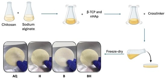
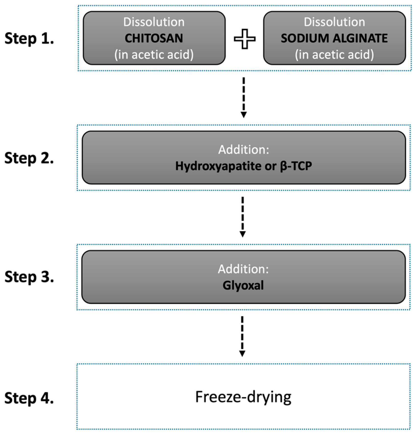
Scaffolds were prepared following four different steps, which are summarized in Figure 1. Briefly, in step A, a 2% (m/v) CT and SA in a 1% (v/v) acetic acid aqueous solution were prepared. Both solutions were left under magnetic stirring at room temperature overnight. After their complete dissolution, the solutions were mixed together.
In step B, calcium phosphates were added to the polymeric solution. For that, 1 wt% β-TCP and/or nHAp were added to the polymeric solution in three different proportions: 1 wt% β-TCP; 1 wt% nHAp; and 0.7 wt% β-TCP and 0.3 wt% nHAp.
Step C aimed to increase the mechanical resistance of scaffolds by crosslinking the polymeric matrix with 1% (v/v) glyoxal. All samples were magnetically stirred for 30 min.
In the final step (step D), the different formulations were freeze-dryed in order to obtain the final scaffold/scaffold form.
Figure 2 shows a schematic representation of the chemical mechanism of the scaffold’s formation. Four different scaffolds were prepared: AQ—polymeric scaffold; H—polymeric based-scaffold with nHAp; B—polymeric based-scaffold with β-TCP; and BH—polymeric based-scaffold with β-TCP and nHAp (7:3).
2.3. Characterization Methods
All scaffolds were characterized by infrared spectroscopy (FTIR), X-ray diffraction (XRD), scanning electron microscopy (SEM), positron annihilation lifetime spectroscopy (PALS) and evaluation of degradation in distilled water, porosimetry by the ethanol method and mechanical properties, in order to infer about the potential of these scaffolds for cells regeneration.
FTIR spectra were collected in the region between 4000–400 cm−1 with 4.0 resolution and 64 scans. Using the UATR (Universal Attenuated Total Reflectance) accessory, in which samples were subjected to a 64 N pressure by a ZnSe crystal, from Frontier-Perkin Elmer Fourier Transform Infrared (FT-NIR/MIR).
X-ray powder diffraction was used in a Bragg-Brentano θ-2θ the geometry, with CuKα radiation (λ = 1.5406 Å). The acquisition was in the 2θ range from 10° to 90° with a 0.03 step and an acquisition time for each step of 1 s. The diffractometer utilized was a BRUKER D8 ADVANCE.
The morphology of the samples was evaluated using scanning electron microscopy (SEM). Images with different amplifications were obtained in a TESCAN VEGA3 microscope with an electron acceleration voltage of 20 kV.
The pore size of scaffolds was estimated by the method of modified liquid displacement with absolute ethanol [16,17]. Briefly, each scaffold (AQ, B, H and BH) with a predetermined size (15 × 10 × 3 mm) was submerged in a graduated test tube with a defined ethanol volume (V1). After 5 min, the sample was placed in a vacuum desiccator to remove the air and allow ethanol into the pores, and the total volume of scaffold and ethanol after vacuum (V2) was determined. Then, the scaffold impregnated with ethanol was removed from the test tube and was determined the residual ethanol volume in the test tube (V3). The porosity (ε) was then calculated according to Equation (1):
were (V1 − V2) is the void volume of the scaffold and (V2 − V3) is the total volume of the scaffold. This method was performed in triplicate and the average measurement was determined for each scaffold.
The Positron Annihilation Lifetime Spectroscopy (PALS) measurements were performed by detecting the prompt γ-ray (1.28 MeV) from the nuclear decay that accompanies the emission of a positron from the 22Na radioisotope and the annihilation γ-ray (0.511 MeV). A fast-fast coincidence circuit of the PALS setup (featuring Pilot-U scintillators and XP2020 photomultipliers), with a time resolution of approximately 260 ps (fullwidth at half maximum), was used to record the positron lifetime spectra. The positron 22Na source (~5 μCi, closed between Kapton γ foils) was sandwiched by two identical samples. Several spectra were collected at room temperature. The lifetime spectra had a total number of ~2 × 10⁶ integral counts and were evaluated using the LT (version 9) software [18]. This technique is the most efficient method for studying subnanometer size distributions and free volume fractions in polymers [19,20,21,22].
Thermogravimetric analysis (TGA) was performed in a SDT Q500 from Thermal Analysis (TA) Instruments, with 5 mg to 10 mg of sample from room temperature to 600 °C with a heating rate of 10 °C/min in a nitrogen atmosphere with a flow rate of 100 mL/min.
Mechanical measurements were performed at room temperature on rectangular samples of 15 × 10 mm and a thickness between 3–4 mm, in an Inspekt mini-series equipment (Hegewald & Peschke) with a loading cell of 50 N using a strain from 0 to 25%. The scaffolds were submitted to uniaxial compression-decompression static tests with a strain rate of 1 mm/min. The mechanical parameters were calculated from the average of triplicate measurements. The Young’s modulus (E) was determined in the initial linear zone of elasticity. Destructive tests (compression to the limit) were also performed with a cell of 3 kN.
The total degradation time of the prepared scaffolds was evaluated in PBS at 37 °C, in a shaker. Samples with size 10 × 10 × 3 mm were dried until constant weight, then submerged in PBS and incubated in a shaker at 100 rpm and 37 °C.
3. Results
3.1. Fourier-Transform Infrared Spectroscopy (FTIR)
Figure 3 shows the spectra obtained from polymers (sodium alginate and chitosan) and the polymeric scaffold (AQ), while in Figure 4 are shown the spectra of the different formulated scaffolds. From Figure 3, some changes can be observed in the position of some bands, namely, the appearance or disappearance of peaks when compared with chitosan and sodium alginate spectra individually due to the interactions between these polymers. AQ spectrum (Figure 3c) presents a more intense band at 3500–3100 than in the individual polymers, which is justified by the formation of the new hydrogen bonds between and groups of chitosan and and of sodium alginate. The appearance of a peak at 1721 is related with the stretching of groups, thus the crosslinking [23]. However, the intense peak of the first amine (at 1652 ) disappeared, possibly due to an overlap with the imine bond band from the crosslinking of glyoxal with chitosan [24]. The crosslinking reaction is characterized by the presence of imine bonds (C = N) formed from and groups of chitosan and the −C = O groups of glyoxal. Moreover, the peak at 1582 , from the amide II, is more evident when compared to the pure chitosan spectrum, due to the presence of sodium alginate. These changes confirm the formation of a strong interaction between negatively charged carboxylic groups of sodium alginate with the positively charged amine groups of chitosan, as well as the crosslinking.
In Figure 4 is evident some similarity between the obtained spectra, due to their polymeric base. All spectra in Figure 4 show a band between 3300–3200 assigned to the – vibrational stretching, also at 1408 and 1555 are present bands assigned to the symmetrical and asymmetric stretching of COO− from sodium alginate [25] and at 1020 cm−1 is shown the characteristic stretching of polysaccharides. However, differences between mixed-matrix scaffolds and the polymeric one can be observed due to the addition of calcium phosphates. Figure 4b, scaffold H (with nHAp), shows two bands at 559 and 599 , which are assigned to the group and a small peak at 1300 is detected due to groups and polymer groups interactions [26]. The spectrum of scaffold B (Figure 4c) shows bands from groups of β-TCP at 943 and 601 [27]. The BH scaffold spectrum (Figure 4d) is similar to scaffold B and H spectra, showing the characteristic bending band at 599 and the absorption bands at 600–610 and 550–570 which are associated with these inorganic materials.
3.2. X-ray Diffraction (XRD)
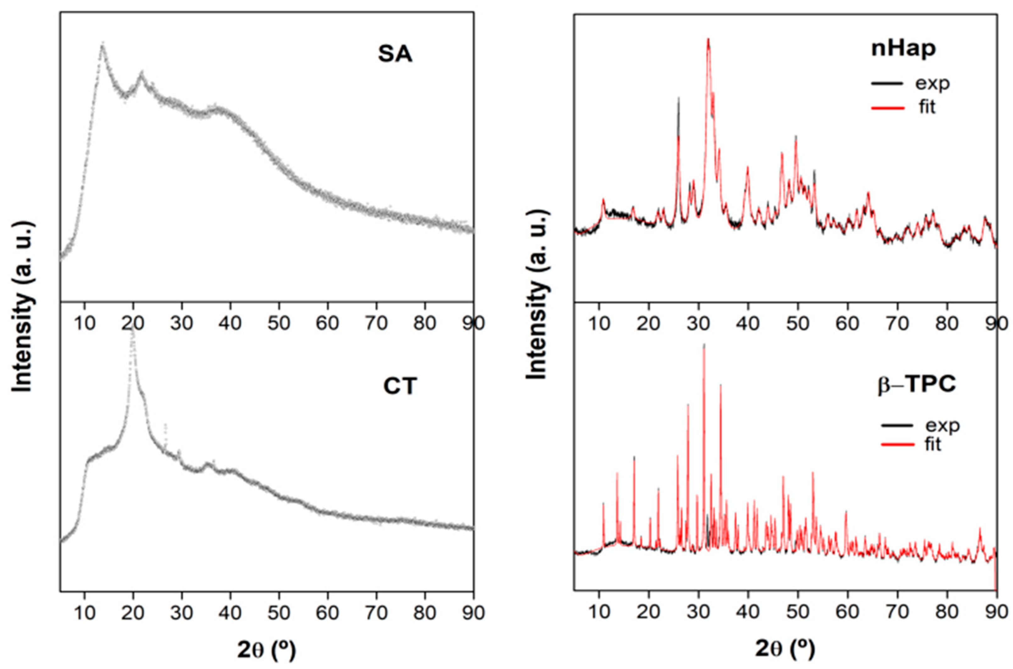
XRD is one of the main techniques used to characterize materials, since it has the ability to determine crystalline phases present in organic and inorganic materials [28]. Figure 5 shows the XRD diffractograms of the starting materials (SA, CT, nHap and β-TCP).
Sodium Alginate (Figure 5 (SA)) is semi-crystalline [29], because the characteristic diffraction peak values for 2θ at 13.5°, 17° and 22° are observed, due to the reflections of the polygururonate unit of polymanuronate as well as an amorphous region [29]. Chitosan diffractogram (Figure 5 (CT)) shows also different morphisms as already seen in literature [30]: amorphous bands and a crystalline peak at 2θ = 20° are observed [25,31]. More crystalline peaks should have been detected, namely at 10°, however their absence can be explained since the crystallinity parameter depends on CT degree of deacetylation. Higher deacetylation degree leads to higher crystallinity [32]. Thus, the diffractograms of this polysaccharide are versatile, and can encompass several degrees of deacetylation.
For these two polymers (SA and CT) no sheets in the JCP database were found for comparative analysis between theoretical values and experimental values obtained. On the other hand, for nHap and β-TCP diffractograms (Figure 5 (nHap) and (β-TCP)) theorical and experimental values were adjusted for each sample, due to knowledge of JCPDF data for each reagent. Overall, it is possible to conclude that both inorganics have crystalline morphism as predicted. nHap belongs to the hexagonal P63/m spatial group (JCPDF 00-64-0738) and β-TCP belongs to the R-3c spatial group (JCPDF 09-0169). The crystallite size of nHap was 18.1 nm as obtained by Scherrer formula. It is in accordance with the nanocrystalline nature of the hydroxyapatite starting material.
Figure 6 shows the diffractograms obtained for the prepared scaffolds. From Figure 6, for AQ scaffolds, it was possible to observe the phases of each polymer: 2θ = 20° peak assigned to the pure chitosan; and two visible regions at 2θ = 5–15° assigned to sodium alginate, which were not visible in SA pure diffractogram (Figure 6 (SA)) but are reported in the literature [33] and at 2θ = 35–40° also assigned to SA [34]. The diffractogram of AQ scaffolds basically presents a non-crystalline structure.
Scaffolds BH, H and B, in Figure 6, present a semi-crystalline structure, with amorphous regions due to the polymers and crystalline regions related to the calcium phosphates. H scaffold has less crystallinity and nHAp characteristic peaks were well adjusted to the diffractogram. A 25 nm crystallite size was obtained using Scherrer equation. However, SA and CT characteristic peaks are not visible, but may be masked by the low crystallinity derived from the interactions between the three materials. Scaffold B shows to be more crystalline than scaffold H, however an amorphous region with 2θ = 0–20° is still observed related to sodium alginate. It is possible to adjust well the characteristic peaks of β-TCP and observe a characteristic peak of chitosan at 2θ = 10°. The crystallite size obtained for this ceramic was 256.7 nm. BH scaffold pattern was qualitatively adjusted with β-TCP, but a peak due to Hap is still observed. It is possible to infer the success of the formation of a new compound by the preparation method used. Such a compound was already obtained by Wongwitwicht et al. [13]. The size of crystallites present in the sample are 171.7 nm.
The size of BH scaffold crystallite decreased when compared to scaffold B, while the nHAp size remain of the same order of magnitude as in scaffold H. It is important to note that human bone has a 20~nm crystalline size [35,36], so it’s expected that scaffolds with similar size of crystallites are more favorable in bone repair and regeneration. Also, these phosphates can assist the connection between the implant and human bone, through the apatite layer.
3.3. Scanning Electron Microscopy (SEM)
SEM images were collected both at crossections (cryogenic fracture) and surfaces of the samples. The different scaffolds formulations led to different pore sizes as can be seen in Figure 7 and Figure 8. All scaffolds present the minimum requirement of pore size since for cell tissue regeneration, pores should be between 40–100 μm to support osteoid matrix growth [13]. Pore size is crucial in order to provide a favorable environment for bioactive materials to reveal their osteoconductive and osteoinductive abilities.
Figure 7a and Figure 8a show that the polymeric scaffolds (AQ) were formed by several circular and well-defined pores, with sizes between 5–150 μm, which were interconnected. AQ scaffold pores were smaller than those of composite scaffolds (B, H, BH). This fact might be related to the crosslinking reaction between SA and CT with glyoxal as crosslinker agent, which occurred without interference from the calcium phosphates, leading to a more efficient bonding between their polymeric chains, thus making the polymeric structure more compact with smaller and circular pores.
Composite scaffolds (B, H and BH) pores were more irregular, larger and with less interconnectivity between them. Their size varies between 5–200 μm, which is consistent with the literature [26,37,38]. In addition, it is possible to detect well-compact structures due to the good miscibility between the groups of calcium phosphates and groups of chitosan [38] and to the strong electrostatic bonds and/or hydrogen interactions between and sodium alginate [39].
3.4. Porosity Determination by Ethanol Method
The scaffolds average pore size obtained by the method of modified liquid displacement with absolute ethanol is shown in Table 1.
The addition of the calcium phosphates led to an increase in the porosity of the scaffolds (B, H and BH) when compared to the polymeric one. The fact that the polymeric scaffold AQ presented lower porosity corroborates with SEM results (Figure 7 and Figure 8), confirming that its porous structure presents smaller pores than the composite scaffolds, due to higher degree of crosslinking of AQ scaffold.
3.5. Positron Annihilation Lifetime Spectroscopy
This non-destructive technique probes localizes free volumes between molecular chains in polymeric structures. In this technique, the anti-electron, that is, the positron, is employed as a probe and monitors the lifetime of the positron and Positronium, Ps (a bound atom which consists of an electron and the positron), in the polymeric materials. Due to the positron’s positive charge, itself and the Ps are repelled by the polymer core electrons and trapped in open spaces, that is, the free volume of the polymer. The trapped Ps could appear either as a para-Positronium (p-Ps, spin singlet state) or as an ortho-Positronium (o-Ps, triplet spin state), with a relative abundance of 1:3, respectively. The annihilation photons come from these open spaces mainly, and the results of the positron annihilation lifetime (PAL) measurements give evidence that the positron and the Ps are located in these pre-existing free volumes in polymers. In PAL measurements, the observed lifetime (τ) is the reciprocal of the integral of the positron and the electron densities at the site where the annihilation takes place [40]. A larger hole, which has a lower average electron density, is expected to have a longer Ps lifetime. A correlation between the free volumes in molecular systems and the observed o-Ps has been postulated [41]. This correlation is expressed in a semi-empirical equation (Equation (2)) between the o-Ps lifetime () and the mean radius of holes (R).
where and R are in the units of nanosecond and angstroms, respectively, and ∆R (= 1.66 Å) is the best fitting parameter between observed o-Ps lifetimes and known mean hole radii in porous materials.
With Equation (2) the mean free volume hole size in the polymeric material can be determined. As the holes are assumed to have a spherical shape, this lifetime is related to a mean radius R. With this assumption, the correspondent free volume cavity was calculated with the Equation (3):
The intensity of the o-Ps lifetime component, , is often treated as a measure of the density of the holes [42]. The free volume fraction (Fv), Equation (3), is directly related to and through the following Equation (4) [41]:
where C is an empirical scaling constant that reflects the probability of o-Ps formation.
The PALS parameters (lifetime and intensity), hole radii and free volume cavity associated with o-Ps lifetime for scaffold are shown in Table 2.
Table 2 shows that the prepared scaffolds have, inside the polymeric structure, pore free volumes within the sub-nanometric size (Vp < 1000 Å3 = 1 nm3). This result agrees well with the existence of the amorphous phase in the scaffold samples, thus defining their nanoporosity. The nanoporisity of the scaffold promotes the interconnectivity between the cavities. According to the literature, Vp is an important parameter in tissue engineering, since it is essential for the diffusion of molecules although the material and is also related with the material mechanical properties and interface phenomena [43]. Moreover, it is also known that nanopores contribute to the osteoclastogenis. Osteoclasts can promote bone formation through communication with osteoblastic cells. In this process, osteoclasts will recruit osteoblasts and promote osteogenic differentiation, which is an asset in bone tissue regeneration [44].
3.6. Thermogravimetric Analysis
Figure 9 shows the TGA curves obtained for the prepared scaffolds. The DTG curves, also in Figure 9, show the inflection points which represent the maximum peak. These peaks are resumed in Table 3 along with the mass loss percentage of the thermal decomposition in each stage.
From Figure 9a can be seen that AQ scaffold showed a higher and faster degradation rate, evident from the curve slope, relatively to the other scaffolds [45]. Also, AQ scaffold presented two degradation stages, while composite scaffolds showed three.
Stage 1 referred in Table 3, occurred at around 35–40 °C and corresponded to water evaporation that was retained during the lyophilization process. In this stage, AQ scaffold showed a second transition temperature and at 130 °C which can be characterized by the exit of free water molecules that were retained into the polymeric structure [23].
At Stage 2, around 200 °C and 270 °C, the polymers functional groups start to degrade, such as amine and carboxyl groups. Also deacetylation occurs, partial depolymerization of chitosan chains and organic matter decomposition [23]. For AQ scaffold another peak at 297.62 °C, regarding to electrolyte complex decomposition, is present, meaning that this scaffold needs higher temperature to rupture chemical bonds due to the higher crosslinking effect already confirmed in the previous sections. Moreover, at this stage, AQ scaffolds lost most of its mass, presenting a 33.11 wt.% loss, while composites scaffolds lost 22.33 wt.%, 30.17 wt.% and 24.04 wt.% (B, H and BH, respectively).
After 400 °C, Stage 3, started the groups decomposition [46,47], however, both nHap and β-TCP are known to start to degrade for temperature above 700 °C [48], which justifies the high residue for the mixed-matrix scaffolds.
It should also be noticed that all scaffolds were stable at physiological body temperature.
3.7. Mechanical Tests
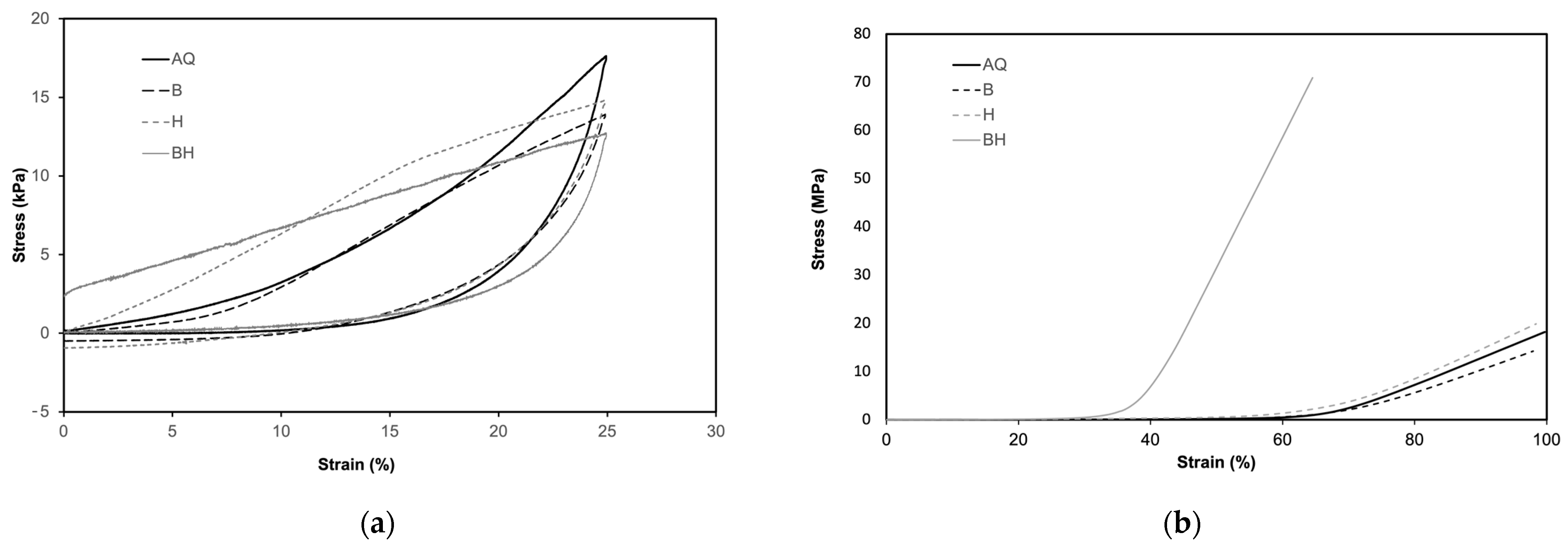
Cell regeneration is essential and, in some extent, mediated by load bearing and cellular behavior, therefore a scaffold must be flexible and resistant to compression [49]. Figure 10a shows the stress-strain compression-decompression curves and indicate that all scaffolds recover almost totally after 25% strain compression, only BH scaffold slightly derives from this tendency. These results corroborate with the SEM images which showed more compact structure with lower porosity but bigger pores for the scaffolds with phosphates. Moreover, the stress-strain curves to maximum load presented in Figure 10b, also shows a different tendency for BH scaffolds. BH scaffold is much stiffer than the other scaffolds, meaning that the mixture of the two phosphates led to an increase in the stiffness of the composite, which means that the pores are more compact [50,51]. These results corroborate with the ones obtained for porosity.
In Table 4 is shown the Young’s modulus, which was evaluated from the linear region of stress/strain loading curve of the compression test and the compressive stress after 25% strain. Scaffolds with β-TCP showed lower Young’s modulus while scaffolds with nHAp showed higher Young’s modules. The first result might be explained by the existence of a poor interfacial bonding between β-TCP particles and the polymers blend [51], while the increase of Young’s modulus with the addition of nHAp is in accordance with the knowledge that phosphates are known for conferring mechanical resistance to scaffolds [52]. This might also explain the lower compressive stress after 25% strain for scaffolds with nHAp along with the lower porosity observed and more compact structure.
3.8. Degradation
During the implantation period the scaffold must be biodegraded and at the same time provide a template for new cells to grow. In addition, mechanical properties must be preserved during this biodegradation so that cells can proliferate, and nutrient transportation be allowed while tissue regeneration occurs. Therefore, in order to evaluate the degradation time of the prepared scaffolds, the total degradation time was measured in PBS. After 20 days, the scaffolds began to lose their structure. B, H and BH scaffolds showed to be the most brittle, while AQ scaffold remained more constant over this time. After 22 and 27 days, BH and B scaffolds disaggregated, respectively. H scaffold took 34 days, and the last one was AQ scaffold, which took 37 days. These results are inline with SEM and the method of liquid displacement, which demonstrated smaller pores for AQ scaffolds, therefore the impregnation of water inside the scaffolds structure is more difficult, thus leading to a lower water degradation.
4. Conclusions
Materials selection and manufacturing processes are the main factors for the physico-chemical, biological and mechanical properties for these 3D structures. This work aimed for better performance and less secondary effects of bone replacements when compared to the currently used materials. For this, four sodium alginate/chitosan-based scaffolds were prepared and the influence of two different calcium phosphates (nHAp and β-TCP) were studied, as well their mixture in a biopolymeric matrix (AQ), sodium-alginate/chitosan & nHAp (H), sodium-alginate/chitosan & β-TCP (B) and sodium-alginate/chitosan & nHAp/β-TCP (BH).
All membranes presented an adequate porosity degree, with a porosity above 50% with interconnectivity between pores, which are fundamental characteristics for mimicking the cells environment in tissue engineering. It was also found that the addition of phosphates improved the thermal stability, mechanical properties and increased the porosity of the composite membranes. Furthermore, BH membranes, formulated with the two calcium phosphates, showed to be stiffer with a more compact structure, which are in agreement with several scientific paper that state the improvement of nHAp membranes properties, such as degradability and surface characteristics, with the addition of a secondary inorganic phase with a lower melting point, as β-TCP. In general, all prepared membranes/scaffolds showed good potential for tissue regeneration applications in future studies.
Author Contributions
Conceptualization, P.A. and B.F.O.C.; methodology, P.A., R.L., P.M.G. and B.F.O.C.; software, P.M.G. and B.F.O.C.; validation, P.A., P.M.G. and B.F.O.C.; formal analysis, P.A., R.L., P.M.G. and B.F.O.C.; investigation, R.L. and P.A.; resources, P.A. and B.F.O.C.; data curation, P.A., P.M.G. and B.F.O.C.; writing—original draft preparation, P.A., R.L., P.M.G. and B.F.O.C.; writing—review and editing, P.A., P.M.G. and B.F.O.C.; visualization, P.A., P.M.G. and B.F.O.C.; supervision, P.A. and B.F.O.C.; project administration, P.A.; funding acquisition, P.A. and B.F.O.C. All authors have read and agreed to the published version of the manuscript.
Funding
This research was funded by Strategic Research Center (CERES) Project UIDB/EQU/00102/2020 and project 2022.02495.PTDC (https://0-doi-org.brum.beds.ac.uk/10.54499/2022.02495.PTDC) of the Call for R&D Projects in All Scientific Domains—2022, funded by FCT—Fundação para a Ciência e a Tecnologia. Access to TAIL-UC facility was funded under QREN-Mais Centro Project No. ICT_2009_02_012_1890.
Institutional Review Board Statement
Not applicable.
Data Availability Statement
The raw/processed data required to reproduce these findings cannot be shared at this time due to technical or time limitations, but will be sent upon request.
Acknowledgments
Access to TAIL-UC facility funded under QREN-Mais Centro Project No. ICT_2009_02_012_1890 is gratefully acknowledged.
Conflicts of Interest
The authors declare no conflicts of interest. The funders had no role in the design of the study; in the collection, analyses, or interpretation of data; in the writing of the manuscript; or in the decision to publish the results.
References
- Lidgren, L.; Gomez-Barrena, E.; Duda, G.N.; Puhl, W.; Carr, A. European musculoskeletal health and mobility in Horizon 2020. Bone Jt. Res. 2014, 3, 48–50. [Google Scholar] [CrossRef]
- Tomé-Bermejo, F.; Piñera, A.R.; Alvarez, L. Osteoporosis and the management of spinal degenerative disease (II). Arch. Bone Jt. Surg. 2017, 5, 363–374. [Google Scholar]
- Götz, W.; Tobiasch, E.; Witzleben, S.; Schulze, M. Effects of Silicon Compounds on Biomineralization, Osteogenesis, and Hard Tissue Formation. Pharmaceutics 2019, 11, 117. [Google Scholar] [CrossRef]
- Chaudhary, C.; Garg, T. Scaffolds: A novel carrier and potential wound healer. Crit. Rev. Ther. Drug Carr. Syst. 2015, 32, 277–321. [Google Scholar] [CrossRef] [PubMed]
- Rodríguez-vázquez, M.; Vega-ruiz, B.; Ramos-zúñiga, R.; Saldaña-koppel, D.A.; Quiñones-olvera, L.F. Chitosan and Its Potential Use as a Scaffold for Tissue Engineering in Regenerative Medicine. BioMed Res. Int. 2015, 2015, 1–15. [Google Scholar] [CrossRef]
- Venkatesan, J.; Bhatnagar, I.; Manivasagan, P.; Kang, K.H.; Kim, S.K. Alginate composites for bone tissue engineering: A review. Int. J. Biol. Macromol. 2015, 72, 269–281. [Google Scholar] [CrossRef]
- Gierszewska, M.; Ostrowska-Czubenko, J.; Chrzanowska, E. pH-responsive chitosan/alginate polyelectrolyte complex membranes reinforced by tripolyphosphate. Eur. Polym. J. 2018, 101, 282–290. [Google Scholar] [CrossRef]
- Azeredo, H.M.C.; Waldron, K.W. Crosslinking in polysaccharide and protein films and coatings for food contact—A review. Trends Food Sci. Technol. 2016, 52, 109–122. [Google Scholar] [CrossRef]
- Oryan, A.; Kamali, A.; Moshiri, A.; Baharvand, H.; Daemi, H. Chemical crosslinking of biopolymeric scaffolds: Current knowledge and future directions of crosslinked engineered bone scaffolds. Int. J. Biol. Macromol. 2018, 107 Pt A, 678–688. [Google Scholar] [CrossRef]
- Shangari, N.; O’Brien, P.J. The cytotoxic mechanism of glyoxal involves oxidative stress. Biochem. Pharmacol. 2004, 68, 1433–1442. [Google Scholar] [CrossRef]
- Wang, L.; Stegemann, J.P. Glyoxal crosslinking of cell-seeded chitosan/collagen hydrogels for bone regeneration. Acta Biomater. 2011, 7, 2410–2417. [Google Scholar] [CrossRef]
- Bròdano, G.B.; Giavaresi, G.; Lolli, F.; Salamanna, F.; Parrilli, A.; Martini, L.; Griffoni, C.; Greggi, T.; Arcangeli, E.; Pressato, D.; et al. Hydroxyapatite-based biomaterials versus autologous bone graft in spinal fusion: An in vivo animal study. Spine 2014, 39, E661–E668. [Google Scholar] [CrossRef]
- Wongwitwichot, P.; Kaewsrichan, J.; Chua, K.; Ruszymah, B.H. Comparison of TCP and TCP/HA Hybrid Scaffolds for Osteoconductive Activity. Open Biomed. Eng. J. 2014, 4, 279–285. [Google Scholar] [CrossRef]
- Schimandle, J.H.; Boden, S.D. Bone substitutes for lumbar fusion: Present and future. Oper. Technol. Orthop. 1997, 7, 60–67. [Google Scholar] [CrossRef]
- Baghbani, F.; Moztarzadeh, F.; Nazari, A.G.; Kamran, A.H.R.; Tondnevis, F.; Nezafati, N.; Gholipourmalekabadi, M.; Mozafari, M. Biological Response of Biphasic Hydroxyapatite/Tricalcium Phosphate Scaffolds Intended for Low Load-Bearing Orthopaedic Applications. Adv. Compos. Lett. 2012, 21, 096369351202100. [Google Scholar] [CrossRef]
- Cui, Y.; Liu, Y.; Cui, Y.; Jing, X.; Zhang, P.; Chen, X. The nanocomposite scaffold of poly(lactide-co-glycolide) and hydroxyapatite surface-grafted with l-lactic acid oligomer for bone repair. Acta Biomater. 2009, 5, 2680–2692. [Google Scholar] [CrossRef]
- Wang, Z.; Gao, T.; Cui, L.; Wang, Y.; Zhang, P.; Chen, X. Improved cellular infiltration into 3D interconnected microchannel scaffolds formed by using melt-spun sacrificial microfibers. RSC Adv. 2016, 6, 2131–2134. [Google Scholar] [CrossRef]
- Kansy, J. Microcomputer program for analysis of positron annihilation lifetime spectra. Nucl. Instrum. Methods Phys. Res. Sect. A Accel. Spectrometers Detect. Assoc. Equip. 1996, 374, 235–244. [Google Scholar] [CrossRef]
- Jean, Y.C.; Van Horn, J.D.; Hung, W.-S.; Lee, K.-R. Perspective of Positron Annihilation Spectroscopy in Polymers. Macromolecules 2013, 46, 7133–7145. [Google Scholar] [CrossRef]
- Gong, W.; Mai, Y.; Zhou, Y.; Qi, N.; Wang, B.; Yan, D. Effect of the Degree of Branching on Atomic-Scale Free Volume in Hyperbranched Poly[3-ethyl-3-(hydroxymethyl)oxetane]. A Positron Study. Macromolecules 2005, 38, 9644–9649. [Google Scholar] [CrossRef]
- Monge, M.A.; Díaz, J.A.; Pareja, R. Strain-Induced Changes of Free Volume Measured by Positron Lifetime Spectroscopy in Ultrahigh Molecular Weight Polyethylene. Macromolecules 2004, 37, 7223–7230. [Google Scholar] [CrossRef]
- Ferreira Marques, M.F.; Gordo, P.M.; Kajcsos, Z.; Lopes Gil, C.; de Lima, A.P.; Queiroz, D.P.; de Pinho, M.N. Positron studies of the temperature-dependence of free volumes in Polydimethylsiloxane/poly(propylene oxide) urethane/urea membranes. Radiat. Phys. Chem. 2007, 76, 129–133. [Google Scholar] [CrossRef]
- Kulig, D.; Zimoch-Korzycka, A.; Jarmoluk, A.; Marycz, K. Study on alginate-chitosan complex formed with different polymers ratio. Polymers 2016, 8, 167. [Google Scholar] [CrossRef]
- Yang, Q.; Dou, F.; Liang, B.; Shen, Q. Studies of cross-linking reaction on chitosan fiber with glyoxal. Carbohydr. Polym. 2005, 59, 205–210. [Google Scholar] [CrossRef]
- Liao, J.; Li, Y.; Li, H.; Liu, J.; Xie, Y.; Wang, J.; Zhang, Y. Preparation, bioactivity and mechanism of nano-hydroxyapatite/sodium alginate/chitosan bone repair material. J. Appl. Biomater. Funct. Mater. 2018, 16, 28–35. [Google Scholar] [CrossRef]
- Bi, Y.; Guang, L.; Ting, Z.; Deng, S.T. Fabrication and characterization of hydroxyapatite/sodium alginate/chitosan composite microspheres for drug delivery and bone tissue engineering. Mater. Sci. Eng. C 2019, 100, 576–583. [Google Scholar] [CrossRef]
- Xidaki, D.; Agrafioti, P.; Diomatari, D.; Kaminari, A.; Tsalavoutas-Psarras, E.; Alexiou, P.; Psycharis, V.; Tsilibary, E.C.; Silvestros, S.; Sagnou, M. Synthesis of hydroxyapatite, β-Tricalcium phosphate and biphasic calcium phosphate particles to act as local delivery carriers of curcumin: Loading, release and in vitro studies. Materials 2018, 11, 595. [Google Scholar] [CrossRef] [PubMed]
- Kolassa, N.; Punzengruber, C.; Suko, J.; Makinose, M. Mechanism of calcium-independent phosphorylation of sarcoplasmic reticulum ATPase by orthophosphate. Evidence of magnesium-phosphoprotein formation. FEBS Lett. 1979, 108, 495–500. [Google Scholar] [CrossRef] [PubMed]
- Fu, S.; Thacker, A.; Sperger, D.M.; Boni, R.L.; Buckner, I.S.; Velankar, S.; Munson, E.J.; Block, L.H. Relevance of rheological properties of sodium alginate in solution to calcium alginate gel properties. AAPS PharmSciTech 2011, 12, 453–460. [Google Scholar] [CrossRef]
- Hussain, R.; Iman, M.; Maji, T.K. Determination of Degree of Deacetylation of Chitosan and Their effect on the Release Behavior of Essential Oil from Chitosan and Chitosan—Gelatin Complex Microcapsules. Int. J. Adv. Eng. Appl. 2014, 37, 69–77. [Google Scholar]
- Chaudhary, D.; Went, M.R.; Nakagawa, K.; Buckman, S.J.; Sullivan, J.P. Molecular pore size characterization within chitosan biopolymer using positron annihilation lifetime spectroscopy. Mater. Lett. 2010, 64, 2635–2637. [Google Scholar] [CrossRef]
- Yuan, Y.; Chesnutt, B.M.; Haggard, W.O.; Bumgardner, J.D. Deacetylation of Chitosan: Material Characterization and in vitro Evaluation via Albumin Adsorption and Pre-Osteoblastic Cell Cultures. Materials 2011, 4, 1399–1416. [Google Scholar] [CrossRef] [PubMed]
- Sundarrajan, P.; Eswaran, P.; Marimuthu, A.; Subhadra, L.B.; Kannaiyan, P. One pot synthesis and characterization of alginate stabilized semiconductor nanoparticles. Bull. Korean Chem. Soc. 2012, 33, 3218–3224. [Google Scholar] [CrossRef]
- Nair, R.M.; Bindhu, B.; Reena, V.L. A polymer blend from Gum Arabic and Sodium Alginate—Preparation and characterization. J. Polym. Res. 2020, 27, 154. [Google Scholar] [CrossRef]
- Danilchenko, S.N.; Kukharenko, O.G.; Moseke, C.; Protsenko, I.Y.; Sukhodub, L.F.; Sulkio-Cleff, B. Determination of the bone mineral crystallite size and lattice strain from diffraction line broadening. Cryst. Res. Technol. 2002, 37, 1234–1240. [Google Scholar] [CrossRef]
- Danilchenko, S.N.; Kalinkevich, O.V.; Pogorelov, M.V.; Kalinkevich, A.N.; Sklyar, A.M.; Kalinichenko, T.G.; Ilyashenko, V.Y.; Starikov, V.V.; Bumeyster, V.I.; Sikora, V.Z.; et al. Characterization and in vivo evaluation of chitosan-hydroxyapatite bone scaffolds made by one step coprecipitation method. J. Biomed. Mater. Res. Part A 2011, 96, 639–647. [Google Scholar] [CrossRef] [PubMed]
- Teng, S.H.; Lee, E.J.; Yoon, B.H.; Shin, D.S.; Kim, H.E.; Oh, J.S. Chitosan/nanohydroxyapatite composite membranes via dynamic filtration for guided bone regeneration. J. Biomed. Mater. Res. Part A 2009, 88, 569–580. [Google Scholar] [CrossRef]
- Kucharska, M.; Butruk, B.; Walenko, K.; Brynk, T.; Ciach, T. Fabrication of in-situ foamed chitosan/β-TCP scaffolds for bone tissue engineering application. Mater. Lett. 2012, 85, 124–127. [Google Scholar] [CrossRef]
- Rajkumar, M.; Meenakshisundaram, N.; Rajendran, V. Development of nanocomposites based on hydroxyapatite/sodium alginate: Synthesis and characterisation. Mater. Charact. 2011, 62, 469–479. [Google Scholar] [CrossRef]
- Kobayashi, Y.; Ito, K.; Oka, T.; Hirata, K. Positronium chemistry in porous materials. Radiat. Phys. Chem. 2007, 76, 224–230. [Google Scholar] [CrossRef]
- Eldrup, M.; Lightbody, D.; Sherwood, J.N. The temperature dependence of positron lifetimes in solid pivalic acid. Chem. Phys. 1981, 63, 51–58. [Google Scholar] [CrossRef]
- Shpotyuk, O.; Ingram, A.; Shpotyuk, O. Free Volume Structure of Acrylic-Type Dental Nanocomposites Tested with Annihilating Positrons. Nanoscale Res. Lett. 2016, 11, 528. [Google Scholar] [CrossRef] [PubMed]
- Axpe, E.; Bugnicourt, L.; Merida, D.; Goiriena-Goikoetxea, M.; Unzueta, I.; Sanchez-Eugenia, R.; Garcia, J.A.; Plazaola, F.; Contera, S. Sub-nanoscale free volume and local elastic modulus of chitosan–carbon nanotube biomimetic nanocomposite scaffold-materials. J. Mater. Chem. B 2015, 3, 3169–3176. [Google Scholar] [CrossRef] [PubMed]
- Hayashi, K.; Ishikawa, K. Effects of nanopores on the mechanical strength, osteoclastogenesis, and osteogenesis in honeycomb scaffolds. J. Mater. Chem. B 2020, 8, 8536–8545. [Google Scholar] [CrossRef] [PubMed]
- Nazeer, M.A.; Yilgör, E.; Yilgör, I. Intercalated chitosan/hydroxyapatite nanocomposites: Promising materials for bone tissue engineering applications. Carbohydr. Polym. 2017, 175, 38–46. [Google Scholar] [CrossRef] [PubMed]
- Liao, C.J.; Lin, F.H.; Chen, K.S.; Sun, J.S. Thermal decomposition and reconstitution of hydroxyapatite in air atmosphere. Biomaterials 1999, 20, 1807–1813. [Google Scholar] [CrossRef] [PubMed]
- Malla, K.P.; Regmi, S.; Nepal, A.; Bhattarai, S.; Yadav, R.J.; Sakurai, S.; Adhikari, R. Extraction and Characterization of Novel Natural Hydroxyapatite Bioceramic by Thermal Decomposition of Waste Ostrich Bone. Int. J. Biomater. 2020, 2020, 1690178. [Google Scholar] [CrossRef] [PubMed]
- Natasha, A.N.; Singh, R.; Bin Abd Shukor, M.H.; Young, T.C.; Purbolaksono, J.; Sopyan, I.; Toulouei, R. Synthesis and Properties of Biphasic Calcium Phosphate Prepared by Different Methods. Adv. Mater. Res. 2014, 970, 20–25. [Google Scholar] [CrossRef]
- McDermott, A.M.; Mason, D.E.; Lin, A.S.P.; Guldberg, R.E.; Boerckel, J.D. Influence of structural load-bearing scaffolds on mechanical load- and BMP-2-mediated bone regeneration. J. Mech. Behav. Biomed. Mater. 2016, 62, 169–181. [Google Scholar] [CrossRef]
- Kumar, B.Y.S.; Isloor, A.M.; Kumar, G.C.M.; Inamuddin; Asiri, A.M. Nanohydroxyapatite Reinforced Chitosan Composite Hydrogel with Tunable Mechanical and Biological Properties for Cartilage Regeneration. Sci. Rep. 2019, 9, 15957. [Google Scholar] [CrossRef]
- Le, H.R.; Qu, S.; Mackay, R.E.; Rothwell, R. Fabrication and mechanical properties of chitosan composite membrane containing hydroxyapatite particles. J. Adv. Ceram. 2012, 1, 66–71. [Google Scholar] [CrossRef]
- Adamski, R.; Siuta, D. Mechanical, Structural, and Biological Properties of Chitosan/Hydroxyapatite/Silica Composites for Bone Tissue Engineering. Molecules 2021, 26, 1976. [Google Scholar] [CrossRef] [PubMed]
Figure 1.
Flow chart of the steps involved in the preparation of the mixed-matrix scaffolds.

Figure 2.
Interaction mechanism between polymeric network (chitosan-sodium alginate), calcium phosphates ions and crosslink agent (glyoxal).
Figure 2.
Interaction mechanism between polymeric network (chitosan-sodium alginate), calcium phosphates ions and crosslink agent (glyoxal).

Figure 3.
FTIR spectra of the polymers (a) chitosan, (b) sodium alginate and (c) AQ scaffolds.

Figure 4.
FTIR spectra of the scaffolds: (a) AQ, (b) H, (c) BH and (d) B.

Figure 5.
XRD diffractogram of (SA) sodium alginate, (CT) chitosan, (nHap) nanohydroxyapatite and (β-TCP) β-TCP.
Figure 5.
XRD diffractogram of (SA) sodium alginate, (CT) chitosan, (nHap) nanohydroxyapatite and (β-TCP) β-TCP.

Figure 6.
XRD diffractogram of AQ, BH, H and B scaffolds.

Figure 7.
Images collected by SEM of the surface of each scaffold with 100×: (a) AQ (sodium-alginate/chitosan); (b) B (sodium-alginate/chitosan & β-TCP); (c) H (sodium-alginate/chitosan & nHAp) and (d) BH (sodium-alginate/chitosan & β-TCP and nHAp).
Figure 7.
Images collected by SEM of the surface of each scaffold with 100×: (a) AQ (sodium-alginate/chitosan); (b) B (sodium-alginate/chitosan & β-TCP); (c) H (sodium-alginate/chitosan & nHAp) and (d) BH (sodium-alginate/chitosan & β-TCP and nHAp).

Figure 8.
Images collected by SEM of the crossection of each scaffold with 100×: (a) AQ (sodium alginate/chitosan); (b) B (sodium-alginate/chitosan & β-TCP); (c) H (sodium-alginate/chitosan & nHAp) and (d) BH (sodium-alginate/chitosan & β-TCP and nHAp).
Figure 8.
Images collected by SEM of the crossection of each scaffold with 100×: (a) AQ (sodium alginate/chitosan); (b) B (sodium-alginate/chitosan & β-TCP); (c) H (sodium-alginate/chitosan & nHAp) and (d) BH (sodium-alginate/chitosan & β-TCP and nHAp).

Figure 9.
TGA curves obtained for (a) AQ, BH, H and B scaffolds and DTG curves for (b) AQ, (c) B, (d) H and (e) BH scaffolds.
Figure 9.
TGA curves obtained for (a) AQ, BH, H and B scaffolds and DTG curves for (b) AQ, (c) B, (d) H and (e) BH scaffolds.

Figure 10.
(a) Elastic recovery test under a uniaxial compression-decompression cycle up to 25% strain using a 50 N cell, (b) Stress–strain curves obtained in uniaxial compression mechanical tests.
Figure 10.
(a) Elastic recovery test under a uniaxial compression-decompression cycle up to 25% strain using a 50 N cell, (b) Stress–strain curves obtained in uniaxial compression mechanical tests.


Table 1.
Porosity (mean ± SD) of each obtained scaffold.
| Scaffold | |
|---|---|
| AQ | 0.51 ± 0.18 |
| B | 0.71 ± 0.07 |
| H | 0.70 ± 0.14 |
| BH | 0.65 ± 0.09 |
Table 2.
Pore free volume (Vp) results obtained from radius (R) and orto_Positronium lifetime () and Intensity () for each scaffold.
Table 2.
Pore free volume (Vp) results obtained from radius (R) and orto_Positronium lifetime () and Intensity () for each scaffold.
| Scaffold | R (Å) | (ns) | (%) | Vp (Å3) |
|---|---|---|---|---|
| AQ | 2.7 ± 0.1 | 1.85 ± 0.02 | 12.2 ± 0.1 | 82.4 ± 9.1 |
| B | 2.7 ± 0.1 | 1.85 ± 0.02 | 11.3 ± 0.1 | 82.4 ± 9.1 |
| H | 2.5 ± 0.1 | 1.69 ± 0.02 | 14.3 ± 0.1 | 65.4 ± 7.9 |
| BH | 2.4 ± 0.1 | 1.59 ± 0.02 | 15.7 ± 0.1 | 57.9 ± 7.2 |
Table 3.
Degradation temperature (Td), mass loss percentage and residue percentage of each scaffold (AQ, H, B and BH).
Table 3.
Degradation temperature (Td), mass loss percentage and residue percentage of each scaffold (AQ, H, B and BH).
| Scaffolds | Td (°C) | Mass Loss (%) | Final Residue (%) | ||||
|---|---|---|---|---|---|---|---|
| Stage 1 | Stage 2 | Stage 3 | Stage 1 | Stage 2 | Stage 3 | ||
| AQ | 38.19 | 234.97 | |||||
| 130.79 | 269.02 | - | 18.76 | 33.11 | - | 23.82 | |
| 297.62 | |||||||
| B | 38.87 | 278.55 | 429.71 | 6.96 | 22.33 | 13.24 | 56.49 |
| H | 39.55 | 209.10 | 436.52 | 6.15 | 30.17 | 17.10 | 43.45 |
| 262.21 | |||||||
| BH | 42.96 | 260.85 | 431.08 | 6.65 | 24.04 | 17.85 | 49.21 |
Table 4.
Mechanical properties of each scaffold.
| Scaffolds | Young’s Modulus (kPa) | Compressive Stress after 25% Strain (kPa) |
|---|---|---|
| AQ | 59.0 ± 2.9 | 15.8 ± 2.6 |
| B | 41.9 ± 1.9 | 10.7 ± 1.5 |
| H | 64.6 ± 5.6 | 7.8 ± 1.0 |
| BH | 52.0 ± 8.8 | 7.8 ± 1.8 |
Disclaimer/Publisher’s Note: The statements, opinions and data contained in all publications are solely those of the individual author(s) and contributor(s) and not of MDPI and/or the editor(s). MDPI and/or the editor(s) disclaim responsibility for any injury to people or property resulting from any ideas, methods, instructions or products referred to in the content. |
© 2024 by the authors. Licensee MDPI, Basel, Switzerland. This article is an open access article distributed under the terms and conditions of the Creative Commons Attribution (CC BY) license (https://creativecommons.org/licenses/by/4.0/).
Share and Cite
MDPI and ACS Style
Lopes, R.; Gordo, P.M.; Costa, B.F.O.; Alves, P. Formulation and Characterization of Chitosan-Based Mixed-Matrix Scaffold for Tissue Engineering. Macromol 2024, 4, 253-268. https://0-doi-org.brum.beds.ac.uk/10.3390/macromol4020014
AMA Style
Lopes R, Gordo PM, Costa BFO, Alves P. Formulation and Characterization of Chitosan-Based Mixed-Matrix Scaffold for Tissue Engineering. Macromol. 2024; 4(2):253-268. https://0-doi-org.brum.beds.ac.uk/10.3390/macromol4020014
Chicago/Turabian StyleLopes, Rita, Paulo M. Gordo, Benilde F. O. Costa, and Patrícia Alves. 2024. "Formulation and Characterization of Chitosan-Based Mixed-Matrix Scaffold for Tissue Engineering" Macromol 4, no. 2: 253-268. https://0-doi-org.brum.beds.ac.uk/10.3390/macromol4020014