
Single-Stage LLC Resonant Converter for Induction Heating System with Improved Power Quality


1
School of Electrical Engineering, Vellore Institute of Technology, Chennai 600127, India
2
Department of Electrical Engineering, Indian Institute of Technology (ISM) Dhanbad, Dhanbad 826004, India
3
Faculty of Transport, Electrical Engineering and Computer Sciences, Department of Electrical Drives and Industrial Electronics, Casimir Pulaski University of Radom, Malczewskiego 29, 26-600 Radom, Poland
*
Author to whom correspondence should be addressed.
Electricity 2024, 5(2), 211-226; https://0-doi-org.brum.beds.ac.uk/10.3390/electricity5020011
Submission received: 20 February 2024
/
Revised: 20 April 2024
/
Accepted: 24 April 2024
/
Published: 26 April 2024
(This article belongs to the Topic Power Converters)
Abstract
:This paper proposes a single-stage direct AC to high-frequency (HF) AC resonant converter based on LLC configuration for induction heating (IH) systems or HF applications. Unlike conventional converters for IH systems, the proposed topology converts the utility frequency to HF AC in a single stage without using a DC link inductor and capacitors and takes the advantages of LLC configuration. Additionally, it improves the power factor to 0.9–1, lowers the THD (3.2% experimentally), and protects against the high-frequency components. An embedded control scheme was designed to keep the HF current oscillating at a resonant frequency, ensuring zero-voltage switching. The operating principle of the proposed topology was investigated using mathematical equations and equivalent circuits. Finally, it was verified using computer simulation, and an experimental prototype of 1.1 kW was developed to demonstrate the proposed topology’s uniqueness.
1. Introduction
Induction heating (IH) is an efficient technique to generate very high temperatures for a wide range of applications, such as industrial heating (brazing and melting of steel) and domestic cooking applications [1,2]. Every application has a unique operating frequency that is determined by the shape of the workpiece and the required skin depth [3,4]. Typically, a high-frequency (HF) current supply is needed for the IH technique in order to produce the HF eddy current in the workpiece that causes the heating effect [5,6]. The skin depth () can be stated as:
where ρ is the electrical resistivity, fs is the switching frequency of the resonant inverter, and μ is the magnetic permeability of the workpiece.
Generally, a series resonant inverter is employed to produce HF alternating current (AC) in IH technology [7,8]. A wide variety of inverter topologies have been developed for the same purpose. Voltage and current resonant inverters are among the most commonly used types [9,10]. Out of these, the voltage-fed resonant inverter is widely used because it has numerous control possibilities [11,12]. Typically, quasi, class D/E, and half-bridge resonant inverters are mostly employed for low-power applications [13,14]. In contrast, full-bridge series resonant topology (FB-SRI) is used for high-power applications [15,16]. Along with these converters, some popular output power control techniques have been developed, including (a) phase shifting (PS), (b) pulse frequency modulation (PFM), (c) asymmetrical voltage cancellation (AVC), (d) pulse density modulation (PDM), and (d) asymmetrical duty cycling (ADC) [17,18,19,20]. Each of the proposed converter topologies and power control techniques has its own merits and demerits, depending on the applications.
The merits and demerits of some conventional resonant converters, along with their control techniques, are given in Table 1.
In the last few years, several configurations of IH converters have been developed, comprising rectification and inversion modes. The input power factor (PF) degradation and the generation of an HF component due to the high switching frequency operation in the inversion mode are the two main problems with the IH system. Recently, boost power factor circuits (BPFCs) have been used as front-end converters to mitigate these problems [21,22], although their extra switches and energy storage elements makes them costly and bulky. Additionally, multiple power conversion stages might lead to various severe issues including poor system reliability, efficiency deterioration, and increases in power loss and electro-magnetic interference (EMI) [23,24]. A direct AC–HF AC converter could be a great way to solve these issues because it not only uses fewer components but also enhances PF and blocks the HF component by adding a passive filter to the input side.
Additionally, it has been observed that the series resonant configuration of the IH load is used in the majority of IH applications. However, previous research works have shown that LLC configuration provides better performance as compared to series resonant configuration (RLC) in terms of short circuit immunity and low current stress in the switches (that are used in the inverter) [25,26,27]. Additionally, with only a small series inductance, the LLC resonant configuration enables exceptional performance with a high quality factor (Q) [28,29,30]. Owing to this, the requirement of an output transformer can be eliminated.
A direct AC to HF AC LLC resonant converter has been proposed in light of the aforementioned power factor issues, high-frequency component generation, multiple power conversion stages, and the desire to benefit from an LLC load resonant configuration. In addition to enhancing the PF at the input side, this converter will enable us to convert grid frequency AC mains to HF AC in a single conversion stage. Additionally, a passive filter comprising an input inductor and a capacitor has been used to prevent the flow of HF components from the load side to the source side.
This paper is classified as follows. In Section II, the proposed converter’s circuit design and operation are described. Circuit analysis, which includes calculation of frequency, output power, voltage, and current gain, is described in Section III. Section IV contains discussion of simulation and experimental findings. In Section V, the conclusion is offered.
2. Proposed Direct AC–HFAC LLC Resonant Converter
2.1. Circuit Description
The proposed topology for the IH system is shown in Figure 1. It consists of four bi-directional switches, and each bi-directional switch comprises two insulated gate bipolar transistors (IGBTs) and two diodes. A bi-directional switch simultaneously conducts the current and blocks the voltage of both polarities based on the control signal.
A series inductor (LS) is connected to a parallel combination of a resonating capacitor (CP) and an IH load in order to create the LLC configuration. A typical induction heating load consists of a workpiece (that is to be heated) and a heating coil or a litz wire-based coil in the case of a domestic IH system. Typically, the IH coil and workpiece (IH load) are considered the transformer’s primary and secondary. Thus, the IH load is referred to as the transformer’s primary, and the obtained equivalent impedance after transferring is represented as a series R–L circuit.
Consequently, to know the electrical behaviour of the proposed topology, the IH coil and its workpiece are modelled as series RL and LP, where RL and LP are the referred equivalent resistance and inductance of the heating coil, respectively.
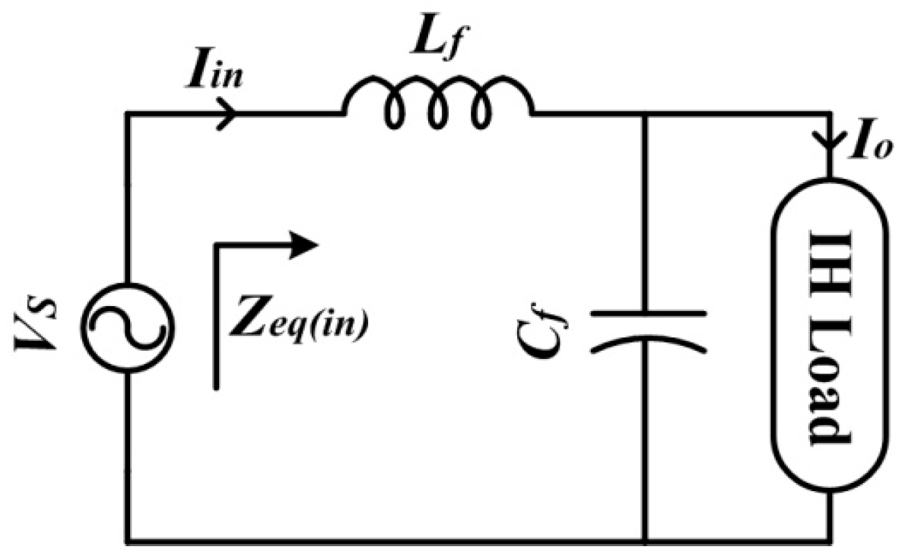
Thereafter, an LC circuit or passive filter is designed which ensures the elimination of the HF component at the input side, as shown in Figure 2. HF components cannot flow back to the input side because the designed passive filter has a high input equivalent impedance (Zeq(in)) at a frequency above 4 kHz. Consequently, power quality at the grid side improves. In Figure 1 and Figure 2, Vs, Iin, Vout, Vo, and Io represent the input voltage, input current, output voltage of the converter, output voltage across the IH load, and output current flowing through the load, respectively.
2.2. Modes of Operation
In accordance with the polarity of the input voltage, the proposed direct AC–HF AC LLC resonant converter has four distinct operating modes. For the positive input half cycle, modes 1 and 2 are defined, and for the negative input half cycle, modes 2 and 3 are defined. The four modes of operation are explained with the assumption of a resistive load because the proposed converter has been made to operate as a resonant converter. Also, the dead time between the pulses and the effect of the input filter is neglected. However, in the prototype implementation, a very small dead time has been considered between the gate signals. Figure 3 shows the circuit topology for each mode of operation and corresponding waveforms.
- Positive input half cycle, Vs > 0
Mode 1 (t0–t1): In the positive input half cycle, the upper IGBTs (SAU, SBU, SCU, and SDU) and lower diodes (DAL, DBL, DCL, and DDL) of bi-directional switches are forward-biased (FB), respectively. Among these FB IGBTs, SAU and SBU receive the gate signal at t0 to t1, as shown in Figure 4. Therefore, the direction of the current at t0 to t1 will be: SAU → DAL → load → SBU → DBL.
Mode 2 (t1–t2): This mode is also for the positive input half cycle. In this mode, SAU and SBU are turned off, as these IGBTs do not receive the gate signal between t1 and t2, as shown in Figure 4. SCU and SDU do receive the gate signal between t1 to t2. Therefore, the direction of the load current reverses in the positive input half cycle: SCU → DCL → load → SDU → DDL.
- Negative input half cycle, Vs < 0
Mode 3 (t2–t3): In the negative input half cycle, the lower IGBTs (SAL, SBL, SCL, and SDL) and upper diodes (DAU, DBU, DCU, and DDU) of bi-directional switches are FB, respectively. Among these FB IGBTs, SDL and SCL receive the gate signal at t2 to t3, as shown in Figure 4. Therefore, the direction of the current at t2 to t3 is: SDL → DDU → load → SCL → DCU.
Mode 4 (t3–t4): This mode is also for the negative input half cycle. In this mode, SDL and SCL turn off, as these IGBTs do not receive the gate signal between t3 and t4, as shown in Figure 4. SBL and SAL do receive the gate signal between t3 and t4. Therefore, the direction of the load current reverses in the negative input half cycle: SBL → DBU → load → SAL → DAU.
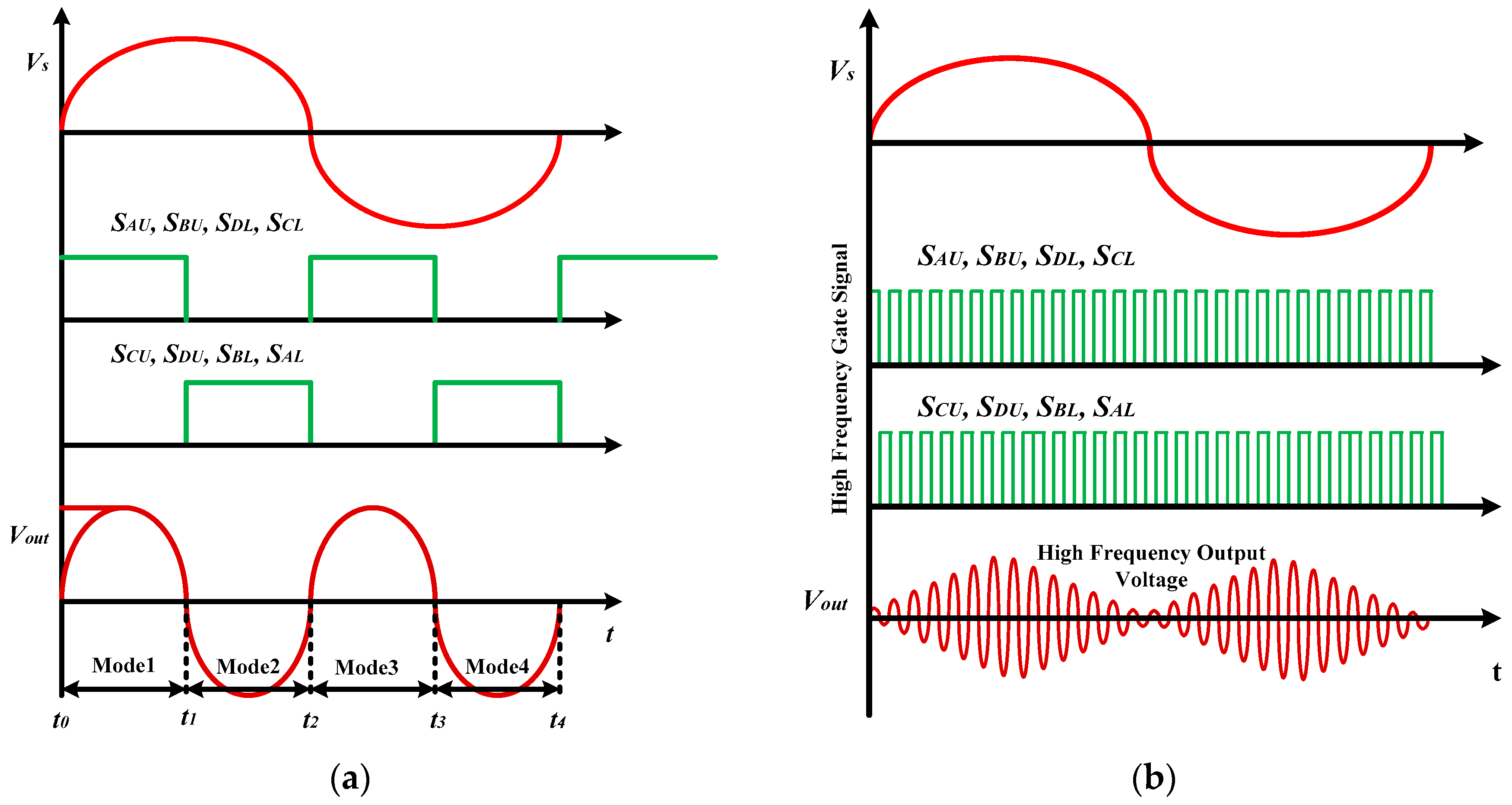
The above modes of operation are explained for 100 Hz-output voltage synthetization, and it can be concluded that the direction of the load current in each input half cycle could be changed by allowing the time period of the conducting IGBTs to be changed in a single stage, as shown in Figure 4a. Consequently, this frequency changer operation of this topology could be deployed in IH technology that requires an HF AC as shown in Figure 4b. The detailed possible switching strategies are given in Table 2.
3. Mathematical Analysis of Proposed Topology
The mathematical analysis of the proposed direct AC–HF AC LLC resonant converter is based on the following assumptions:
- (a)
- All components in the circuit are ideal.
- (b)
- The AC input voltage (Vs) is purely sinusoidal.
- (c)
- The effects of parasitic capacitance are neglected.
- (d)
- The load current is purely HF sinusoidal.
3.1. Calculation of Switching Frequency
The equivalent circuit of the proposed topology based on the LLC tank is shown in Figure 5. In the figure, Vout is the HF output voltage, Ls is the series inductance, and CP is the resonating capacitor connected parallel to the IH load comprised of LP and RL. The proposed direct AC–HF AC LLC resonant converter is made to work at resonant frequency. Thus, in order to obtain resonant frequency, first the equivalent impedance of the LLC resonant tank is determined.
The equivalent impedance of the LLC resonant tank can be determined as:
On solving Equation (2):
On complete rationalization of Equation (3):
where .
To have the active power, the imaginary part of Equation (4) should be equal to zero. Also, RL << LP ~0.
Therefore,
where ω is the angular resonant frequency.
In Equation (7), f is the resonant frequency of the LLC tank, and at this frequency, the maximum power is transferred to the IH load. However, to enable the zero-voltage switching (ZVS), the switching frequency (fs) is selected higher than the calculated resonant frequency (f), ensuring less switching and fewer power losses.
3.2. Quality Factor
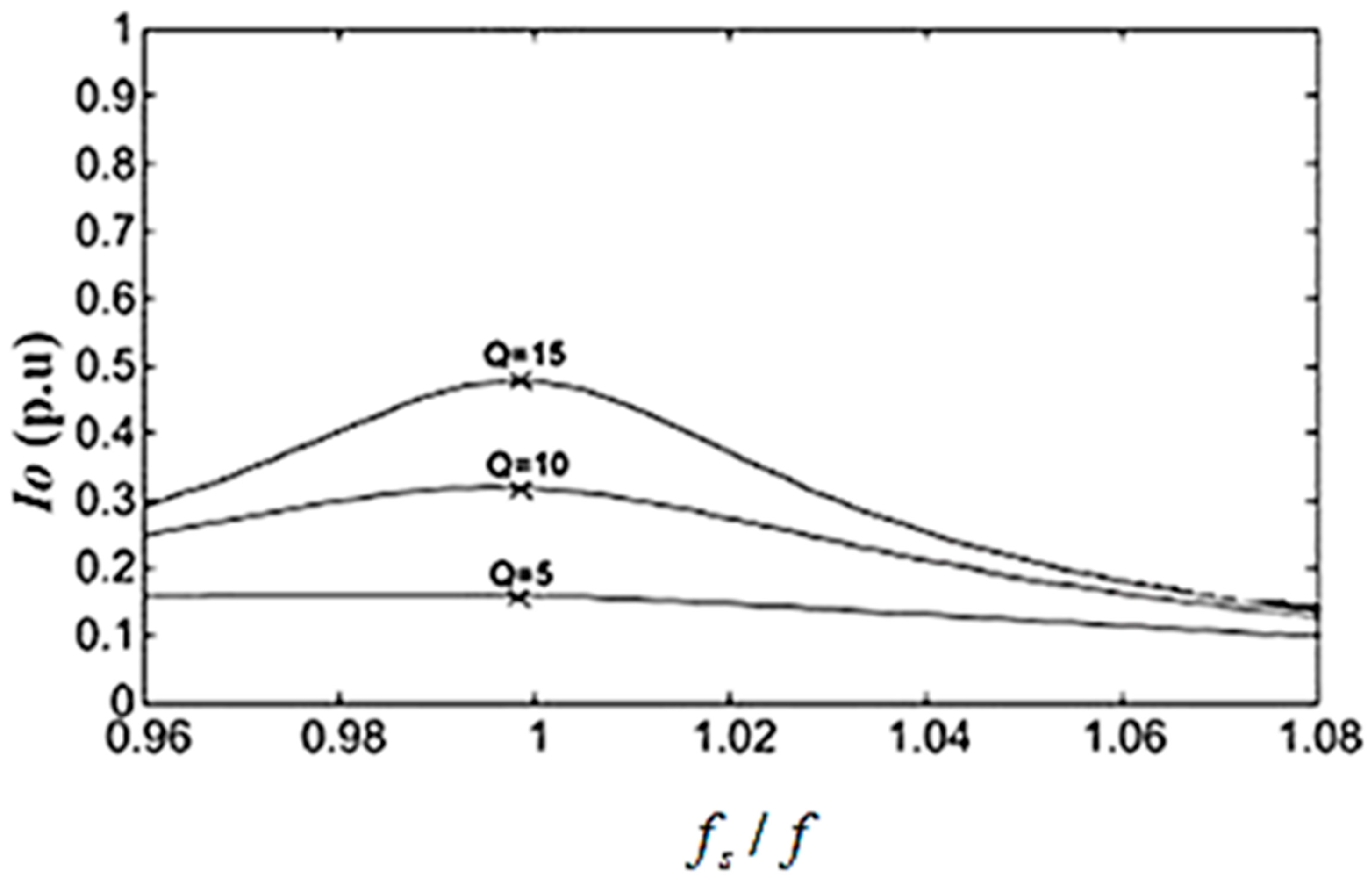
At a higher quality factor, (Q), the resonant inverter normally operates close to the resonant frequency (ωo). In contrast to the induction coil current (Io), as shown in Figure 6, the Q factor has a negligible effect on the resonant frequency, i.e., the peak value of Io occurs at the same frequency, regardless of the Q factor. The peak value of Io is related to the RLC parallel end, as shown in Figure 5, where LS does not play a role in the frequency response of Io. The quality factor (Q) for the second order system can be defined as:
where ωo and α are the resonant frequency and damping coefficient of the second order system, respectively.
Let be the solution of the characteristic polynomial of the system. Now, based on Figure 5, the parallel circuit impedance is:
The characteristic polynomial of the above equation is given as:
Taking into account, the damping coefficient is:
The resonant frequency is:
Therefore, using Equation (8), the quality factor of the parallel circuit is:
In this work, the values of LP and RL for the IH coil were measured through an LCR meter and the switching frequency was kept constant and was usually higher than the resonant frequency (f) to create zero-voltage switching. Thereafter, the values of LS and CP were calculated using Equations (7) and (13).
3.3. Current Gain
As shown in Figure 5, Is is the current that flows through the IGBTs/switches, and it must be the lowest magnitude possible to obtain low current stress in the switches. Alongside it, Io is the IH load current and must be very intense. Thanks to the LLC circuit, it is possible to have low current stress in the switches and to provide great power dissipation in the IH load. This merit of the LLC tank makes it preferable to the SRI (where all the current flows to the IH load through the switches) for IH applications. Therefore, the maximum ratio of Io and Is defined as current gain is very much needed and occurs at resonant frequency (f), as calculated in Equation (7).
Current gain is calculated as:
Thus, modules of GI become:
The current gain at resonant frequency, ()), is given as:
A high current gain allows us to obtain a high heating effect with small Is.
3.4. Voltage Gain
Voltage gain can be defined as the ratio of voltage of the parallel resonant capacitor (CP) to the first harmonic amplitude of the output voltage of the converter, V1. This ratio allows us to evaluate the voltage stress in the parallel resonating capacitor (CP). The voltage gain (Gv) is given as:
Using the voltage division rule in Figure 5:
At resonant frequency (ωo), capacitor voltage (VCP) is given as:
The magnitude of voltage gain (GV(ω)) can be calculated as:
On solving Equation (21), we obtain:
3.5. Calculation of Output Power
Theoretically, the resonant frequency (f) to impart the maximum power to the load is given in Equation (7). Thus, at this frequency, the approximated Zeq is equal to . Therefore, the maximum average output power (Po,ave(m)) transferred to RL at the resonant frequency (f) can be determined as:
However, the proposed topology is designed in order to operate at switching frequency (fs), which is kept higher than the resonant frequency (f) to enable ZVS operation.
Vo can be evaluated by using the Fourier series, which is as follows:
The fundamental output voltage (Vo1) can be determined as:
Therefore, the rms value of Vo1 can be written as:
On assuming maximum average output power (Po,ave(m)) for the above equation, we obtain:
As can be seen from Equation (27), it is obvious that maximum average output power (Po,ave(m)) can be controlled by the duty cycle (D) or switching frequency (fs).
4. Results
Based on the above theoretical analysis, a computer simulation using MATLAB 2015a was performed, and then an experimental prototype with 1100 W was built and tested, validating the feasibility of the proposed topology. The circuit parameters and obtained operational parameters for the developed simulation model and experimental prototype are given in Table 3.
Figure 7 depicts a block diagram of a prototype implementation for the suggested topology. In this block diagram, the proposed converter receives 1-∅, 230 V utility frequency AC (UFAC) and creates HF AC directly without intermediate stages. The HF AC then flows to the IH load via the series inductance LS, reducing switch current stress (Is). An embedded controller has been designed to generate gate signals for the switches, consisting mostly of a zero-crossing detector (ZCD), an Arduino (Atmega 2560), and a driving circuit.
To ensure zero-crossings of input mains, a step-down transformer is used to lower 1-∅, 230 V to 12 V. Then, 12 V AC is delivered to the ZCD, as illustrated in Figure 7. Following that, a diode is employed to remove the negative half of the rectangular pulse. The resulting pulse is perfectly synchronized with the input mains. Subsequently, a synchronized pulse is sent to the Arduino’s interrupt pins (INT0 and INT1). Furthermore, interrupt pins INT0 and INT1 detect the rising and falling edges of the synchronized pulse and create pulses (Vg1 and Vg2) at the required frequencies according to the programming.
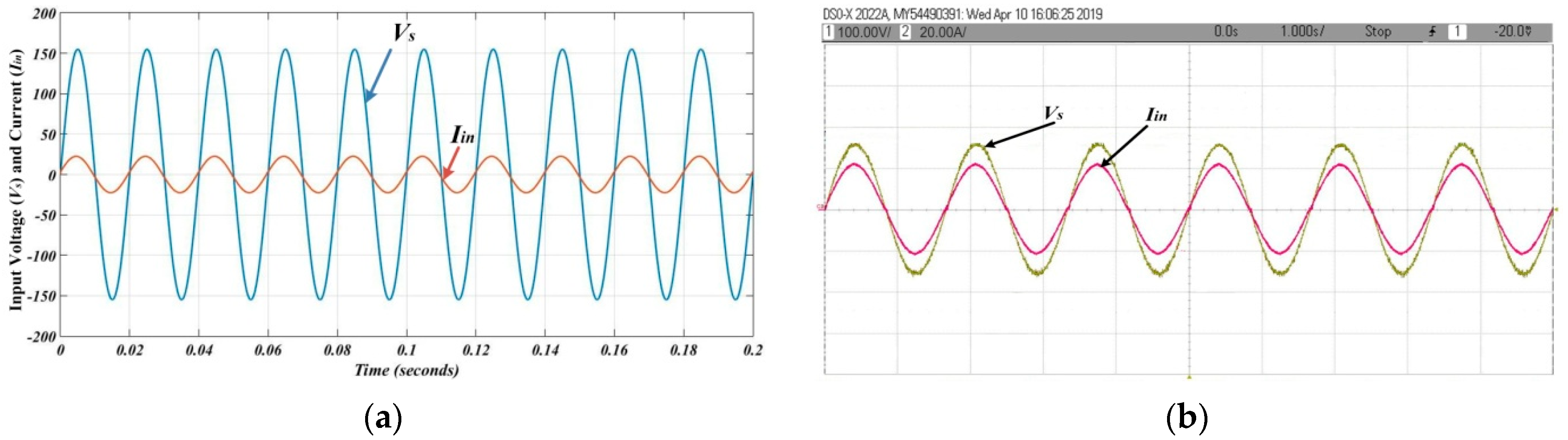
Finally, Vg1 and Vg2 are given to the IGBT switches SAU, SBU, SDL, SCL and SCU, SDU, SBL, SAL of the proposed converter via driver circuits, respectively. The prototype implementation of the proposed IH power supply system is depicted in Figure 8. Each bidirectional switch in this setup is made up of two diodes and two IGBTs. The different voltage and current waveforms are recorded using a digital storage oscilloscope (DSO) and a current sensor probe. Figure 9 presents the modelling and experimental findings concerning the input voltage and current, implying that the input current is devoid of the HF component created during high-switching frequency operation. Furthermore, the obtained input PF (experiment) is 0.92. Thus, it enhances the power quality of the input mains while also protecting against HF components, owing to the passive filter shown in Figure 2.
A digital oscilloscope and current sensor captured the voltage and current waveforms. Figure 9 showcases the simulation and experimental results, demonstrating the input current’s absence of high-frequency (HF) components typically generated by high switching frequencies. This translates to a measured power factor (PF) of 0.92, indicating efficient power utilization and reduced harmonic distortion. This improvement in power quality and HF component protection stems from the passive filter depicted in Figure 2.
Further analysis using a fast Fourier transform (FFT) on the input current (Figure 10) reveals a total harmonic distortion (THD) of 2.03% in simulations and 3.2% experimentally. Both values fall within acceptable ranges for IH applications. Additionally, the recorded root mean square (RMS) values for the input voltage and current are 110 V and 15.87 A, respectively.
The switching frequency of the gate signals, generated from the controller, is kept at 30 kHz, which is greater than the calculated resonant frequency using Equation (7), i.e., 24 kHz, to ensure ZVS condition. ZVS condition not only reduces the switching and power losses but increases the overall efficiency of the converter. The simulation and experimental results of synchronizing gate signals with the input mains through ZCD are shown in Figure 11.
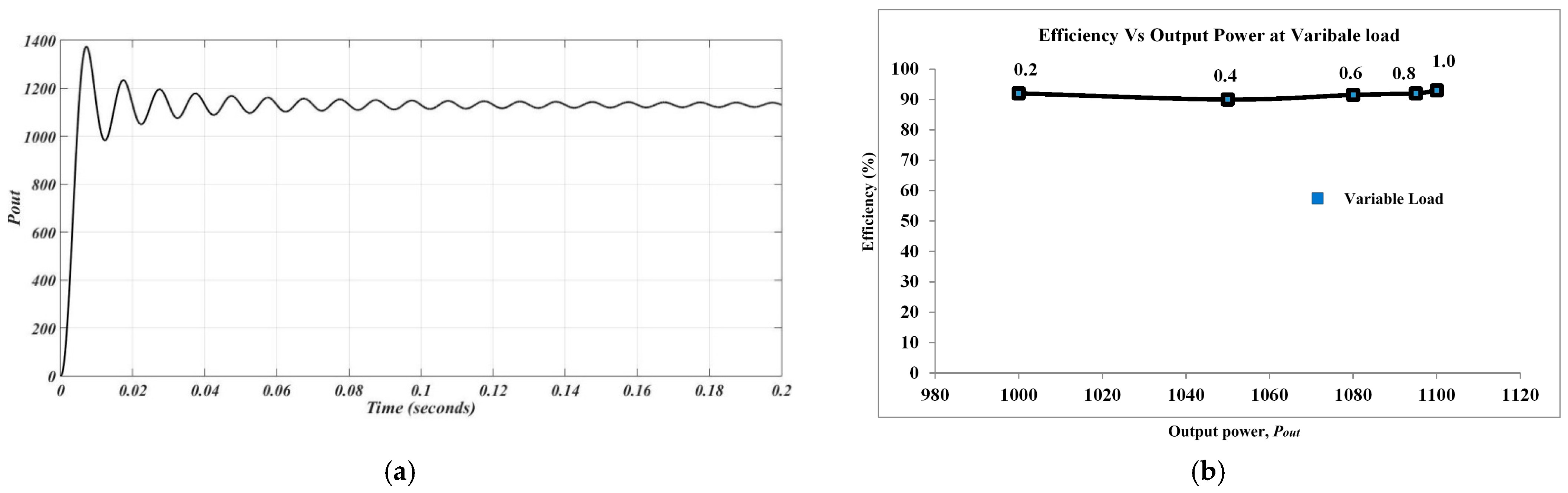
In this work, the IH coil and its load is modelled as LP (52.7 μH) and RL (1 Ω) to study the electrical behaviour of the proposed converter. As is well known, when the converter functions as a resonant inverter, the voltage and current are always in the same phase. Consequently, it can be inferred from Figure 12 that the output voltage and current waveforms are in the same phase, both experimentally and through simulation. Figure 12 shows the simulation and experimental results of the output voltage and current across the IH load, having R.M.S values of 62.22 V and 19.79 A, respectively. The experimentally obtained PF between the output voltage and current was found to be 0.97 (almost unity), which shows the resonant property of the proposed converter. Therefore, the experimental average output power (Po,(ave)) can be calculated as P = VIcosø = 62.22 × 19.79 × 0.97 = 1194 W (approximately). The average output power (Po,(ave)) is shown in Figure 13a.
Furthermore, an extensive efficiency analysis was carried out. As previously indicated, the inductance and resistance of the coil and its load (pot, vessel, etc.) are represented by LP and RL in a series connection, which represents the IH coil and its load. In order to perform an efficiency analysis, load resistance (RL) is varied between 0.1 and 1 Ω, while LP is maintained at a constant value. The power and efficiency of the input/output are calculated for each value of load resistance. Figure 13b displays the resulting output power and efficiency graph at a variable load. On average, 93% efficiency is attained.
As can be seen from the obtained simulation and experimental results, a comparison has been made between the proposed topology and the conventional topology for the IH system in terms of PF, THD, input filter design, controller complexity, and design costs and is shown in Table 4. As can be observed from this table, the proposed topology also improves the power quality in terms of THD and PF. Consequently, the proposed single-stage direct AC to HF AC LLC resonant converter can be effectively deployed in IH systems. This proposed converter’s single drawback is its high switch count, which increases switching losses.
5. Conclusions
In this paper, an 1100 W single-stage direct AC–HF AC LLC resonant converter for IH systems has been proposed; it generates 30 kHz current directly from the utility 50 Hz power supply. An embedded control scheme (using Arduino 2560) is used to generate gate signals. The proposed converter is implemented with four bi-directional switches. The associated circuit operation and mathematical model has been explained to analyze the converter operation. Further, the potency of the proposed topology is validated through MATLAB simulation and experimental results. From the obtained results, the presented work has the following peculiar merits:
- The presented topology converts utility grid-frequency AC to HF AC in a single stage and also maintains the input power factor close to unity simultaneously.
- The implemented control scheme is based on an embedded system having a simple configuration and is easy to implement.
- As LLC configuration is used, it reduces the current stress across the switches and also enables an intense current magnitude across the IH load simultaneously.
- Finally, the proposed topology not only lowers the THD of the input current but also blocks the HF component that receives back flows towards the utility side. Thus, the power quality of the input mains improves.
Therefore, it can be concluded that the presented topology can be effectively applied in the IH application and can also be deployed where HF applications are required.
Author Contributions
Conceptualization, A.K. and A.G.; methodology, A.K.; software, A.K.; validation, P.K.S. and J.R.S.; formal analysis, A.K.; investigation, A.G.; resources, A.G.; data curation, J.R.S.; writing—original draft preparation, A.K.; writing—review and editing, A.G.; visualization, A.K.; supervision, P.K.S. and J.R.S.; project administration, P.K.S. and J.R.S.; funding acquisition, P.K.S. and J.R.S. All authors have read and agreed to the published version of the manuscript.
Funding
This research received no external funding.
Data Availability Statement
The data are contained within the article.
Acknowledgments
Authors acknowledge VIT Chennai and IIT (ISM) Dhanbad for the lab facilities.
Conflicts of Interest
The authors declare no conflicts of interest.
References
- Lucía, O.; Maussion, P.; Dede, E.J.; Burdío, J.M. Induction heating technology and its applications: Past developments, current technology, and future challenges. IEEE Trans. Ind. Electron. 2013, 61, 2509–2520. [Google Scholar] [CrossRef]
- Patil, M.; Choubey, R.K.; Jain, P.K. Influence of coil shapes on temperature distribution in induction heating process. Mater. Today: Proc. 2023, 72, 3029–3035. [Google Scholar] [CrossRef]
- Acero, J.B.L.B.J.; Alonso, R.; Burdio, J.M.; Barragán, L.A.; Puyal, D. Analytical equivalent impedance for a planar circular induction heating system. IEEE Trans. Magn. 2005, 42, 84–86. [Google Scholar] [CrossRef]
- Chaboudez, C.; Clain, S.; Glardon, R.; Rappaz, J.; Swierkosz, M.; Touzani, R. Numerical modelling of induction heating of long workpieces. IEEE Trans. Magn. 1994, 30, 5028–5037. [Google Scholar] [CrossRef]
- Ngoc, H.P.; Fujita, H.; Ozaki, K.; Uchida, N. Phase angle control of high-frequency resonant currents in a multiple inverter system for zone-control induction heating. IEEE Trans. Power Electron. 2011, 26, 3357–3366. [Google Scholar] [CrossRef]
- Musii, R.; Lis, M.; Pukach, P.; Chaban, A.; Szafraniec, A.; Vovk, M.; Melnyk, N. Analysis of Varying Temperature Regimes in a Conductive Strip during Induction Heating under a Quasi-Steady Electromagnetic Field. Energies 2024, 17, 366. [Google Scholar] [CrossRef]
- Millán, I.; Burdío, J.M.; Acero, J.; Lucía, O.; Llorente, S. Series resonant inverter with selective harmonic operation applied to all-metal domestic induction heating. IET Power Electron. 2011, 4, 587–592. [Google Scholar] [CrossRef]
- Dimitrov, B.; Hayatleh, K.; Barker, S.; Collier, G. Design, Analysis and Experimental Verification of the Self-Resonant Inverter for Induction Heating Crucible Melting Furnace Based on IGBTs Connected in Parallel. Electricity 2021, 2, 439–458. [Google Scholar] [CrossRef]
- Neogi, K.; Sadhu, M.; Das, N.; Sadhu, P.K.; Chakraborty, A.; Ganguly, A.; Banerjee, A. A new approach for the stability analysis of high-frequency series resonant inverter-fitted induction heater. Ain Shams Eng. J. 2019, 10, 185–194. [Google Scholar] [CrossRef]
- Aunsborg, T.S.; Duun, S.B.; Munk-Nielsen, S.; Uhrenfeldt, C. Development of a current source resonant inverter for high current MHz induction heating. IET Power Electron. 2022, 15, 1–10. [Google Scholar] [CrossRef]
- Yu, A.; Zeng, X.; Xiong, D.; Tian, M.; Li, J. An Improved Autonomous Current-Fed Push-Pull Parallel-Resonant Inverter for Inductive Power Transfer System. Energies 2018, 11, 2653. [Google Scholar] [CrossRef]
- Kim, N.G.; Jo, S.W.; Han, B.; Choi, H.H.; Kim, M. Highly efficient bidirectional current-fed resonant converter over a wide voltage gain range. IEEE Trans. Ind. Electron. 2020, 68, 10913–10927. [Google Scholar] [CrossRef]
- Miyamae, M.; Ito, T.; Matsuse, K.; Tsukahara, M. Performance of a high frequency quasi-resonant inverter with variable-frequency output for induction heating. In Proceedings of the 7th International Power Electronics and Motion Control Conference, Harbin, China, 2–5 June 2012; pp. 2877–2882. [Google Scholar]
- Mendonça, L.S.; Naidon, T.C.; Raposo, R.F.; Bisogno, F.E. An Unit-less Mathematical Model for Analysis and Design of Class-E Resonant Converters. In Proceedings of the 2019 IEEE 15th Brazilian Power Electronics Conference and 5th IEEE Southern Power Electronics Conference (COBEP/SPEC), Santos, Brazil, 1–4 December 2019; IEEE: Piscataway, NJ, USA, 2019; pp. 1–6. [Google Scholar]
- Gomes, R.; Vitorino, M.A.; Acevedo-Bueno, D.; Correa, M. Multi-Phase Resonant Inverter with Coupled Coils for AC/AC Induction Heating Application. IEEE Trans. Ind. Appl. 2019, 56, 551–560. [Google Scholar] [CrossRef]
- Devara, V.B.; Neti, V.; Maity, T.; Shunmugam, P. Capacitor-sharing two-output series-resonant inverter for induction cooking application. IET Power Electron. 2016, 9, 2240–2248. [Google Scholar] [CrossRef]
- Esteve, V.; Jordán, J.; Dede, E.J.; Bellido, J.L. Enhanced asymmetrical modulation for half-bridge series resonant inverters in induction heating applications. IET Power Electron. 2023, 16, 2482–2491. [Google Scholar] [CrossRef]
- Carretero, C.; Lucía, O.; Acero, J.; Burdío, J.M. Phase-shift control of dual half-bridge inverter feeding coupled loads for induction heating purposes. Electron. Lett. 2011, 47, 670–671. [Google Scholar] [CrossRef]
- Shen, J.; Ma, H.; Yan, W.; Hui, J.; Wu, L. PDM and PSM Hybrid Power Control of a Series-Resonant Inverter for Induction Heating Applications. In Proceedings of the 2006 1ST IEEE Conference on Industrial Electronics and Applications, Singapore, 24–26 May 2006; pp. 1–6. [Google Scholar]
- Burdio, J.M.; Barragan, L.A.; Monterde, F.; Navarro, D.; Acero, J. Asymmetrical voltage-cancellation control for full-bridge series resonant inverters. IEEE Trans. Power Electron. 2004, 19, 461–469. [Google Scholar] [CrossRef]
- Meziane, B.; Zeroug, H. Comprehensive Power Control Performance Investigations of Resonant Inverter for Induction Metal Surface Hardening. IEEE Trans. Ind. Electron. 2016, 63, 6086–6096. [Google Scholar] [CrossRef]
- Franco de Souza, A.; Ribeiro, E.R.; Vicente, E.M.; Tofoli, F.L. Experimental evaluation of active power factor correction techniques in a single-phase AC-DC boost converter. Int. J. Circuit Theory Appl. 2019, 47, 1529–1553. [Google Scholar] [CrossRef]
- Gonçalves, J.T.; Valtchev, S.; Melicio, R.; Gonçalves, A.; Blaabjerg, F. Hybrid three-phase rectifiers with active power factor correction: A systematic review. Electronics 2021, 10, 1520. [Google Scholar] [CrossRef]
- İnci, M.; Büyük, M.; Demir, M.H.; İlbey, G. A review and research on fuel cell electric vehicles: Topologies, power electronic converters, energy management methods, technical challenges, marketing and future aspects. Renew. Sustain. Energy Rev. 2021, 137, 110648. [Google Scholar] [CrossRef]
- Yang, Y.; Wang, H.; Sangwongwanich, A.; Blaabjerg, F. Design for reliability of power electronic systems. In Power Electronics Handbook; Butterworth-Heinemann: Oxford, UK, 2018; pp. 1423–1440. [Google Scholar]
- Pérez-Tarragona, M.; Sarnago, H.; Lucía, Ó.; Burdío, J.M. Design and Experimental Analysis of PFC Rectifiers for Domestic Induction Heating Applications. IEEE Trans. Power Electron. 2018, 33, 6582–6594. [Google Scholar] [CrossRef]
- Espi-Huerta, J.M.; Santamaria, E.J.D.G.; Gil, R.G.; Castello-Moreno, J. Design of the L-LC Resonant Inverter for Induction Heating Based on Its Equivalent SRI. IEEE Trans. Ind. Electron. 2007, 54, 3178–3187. [Google Scholar] [CrossRef]
- Zgraja, J.; Lisowski, G.; Kucharski, J. Autonomous Energy Matching Control in an LLC Induction Heating Generator. Energies 2020, 13, 1860. [Google Scholar] [CrossRef]
- Chudjuarjeen, S.; Sangswang, A.; Koompai, C. LLC resonant inverter for induction heating with asymmetrical voltage-cancellation control. In Proceedings of the 2009 IEEE International Symposium on Circuits and Systems, Taipei, Taiwan, 24–27 May 2009; pp. 2874–2877. [Google Scholar]
- Kranprakon, P.; Sangswang, A.; Naetiladdanon, S. Model predictive control of LLC resonant inverter for induction furnace. In Proceedings of the 2017 International Electrical Engineering Congress (iEECON), Pattaya, Thailand, 8–10 March 2017; IEEE: Piscataway, NJ, USA, 2017; pp. 1–4. [Google Scholar]
- Vishnuram, P.; Ramachandiran, G.; Sudhakar Babu, T.; Nastasi, B. Induction heating in domestic cooking and industrial melting applications: A systematic review on modelling, converter topologies and control schemes. Energies 2021, 14, 6634. [Google Scholar] [CrossRef]
Figure 1.
Proposed configuration of the direct AC–HFAC LLC resonant converter.

Figure 2.
Passive filter.

Figure 3.
Operational modes of the proposed direct AC–HF AC converter: (a) Mode 1; (b) Mode 2; (c) Mode 3; (d) Mode 4.
Figure 3.
Operational modes of the proposed direct AC–HF AC converter: (a) Mode 1; (b) Mode 2; (c) Mode 3; (d) Mode 4.

Figure 4.
Frequency synthesization of the output voltage using the proposed topology: (a) 100 Hz-output voltage synthesization; (b) High-frequency output voltage synthesization.
Figure 4.
Frequency synthesization of the output voltage using the proposed topology: (a) 100 Hz-output voltage synthesization; (b) High-frequency output voltage synthesization.

Figure 5.
Equivalent circuit of the proposed topology.

Figure 6.
Output current (Io) in p.u at different Q factors.

Figure 7.
Block diagram of the prototype implementation.

Figure 8.
Experimental setup of the proposed IH power supply system.

Figure 9.
Input voltage and current: (a) Simulation result; (b) Experimental result (Vs: 100 V/div; Iin: 20 A/div).
Figure 9.
Input voltage and current: (a) Simulation result; (b) Experimental result (Vs: 100 V/div; Iin: 20 A/div).

Figure 10.
FFT spectrum of the input current.

Figure 11.
Gate signals: (a) Simulation result; (b) Experimental result (Vg1 and Vg2: 5 V/div).

Figure 12.
Input voltage and current results: (a) Simulation result; (b) Experimental result (Vo: 80 V/div; Io: 20 A/div).
Figure 12.
Input voltage and current results: (a) Simulation result; (b) Experimental result (Vo: 80 V/div; Io: 20 A/div).

Figure 13.
(a) Average output power (Pout) and (b) efficiency analysis.


Table 1.
Merits and demerits of conventional resonant converters with their control algorithms [1,3].
| Converter Topology | Control Algorithm | Merits | Demerits |
|---|---|---|---|
| Two-output series resonant inverter with common capacitor | Pulse width modulation control |
|
|
| Full bridge converter | Pulse density modulation, frequency modulation, phase shift modulation |
|
|
| Single-stage boost full bridge resonant inverter | Phase shift PWM technique |
|
|
| Multi-modulated converters using full bridge topology | Deadband current control technique |
|
|
| Multi-frequency resonant converter | Deadband current control technique |
|
|
Table 2.
Switching Strategies.
| Input Voltage (Vs) | Forward-Biased Switches | Modes | IGBTs/Diodes Status | Time Interval | Output Voltage (Vout) |
|---|---|---|---|---|---|
| Vs > 0 | (SAU, SBU, SCU, SDU) and (DAL, DBL, DCL, DDL) | Mode 1 | (SAU/DAL/SBU/DBL) ON (SCU/DCL/SDU/DDL) OFF | t0–t1 | Vout > 0 |
| Mode 2 | (SAU/DAL/SBU/DBL) OFF (SCU/DCL/SDU/DDL) ON | t1–t2 | Vout < 0 | ||
| Vs < 0 | (SAL, SBL, SCL, SDL) and (DAU, DBU, DCU, DDU) | Mode 3 | (SDL/DDU/SCL/DCU) ON (SBL/DBU/SAL/DAU) OFF | t2–t3 | Vout > 0 |
| Mode 4 | (SDL/DDU/SCL/DCU) OFF (SBL/DBU/SAL/DAU) ON | t3–t4 | Vout < 0 |
Table 3.
Circuit and operational parameters.
| Circuit Parameters | Operational Parameters | ||
|---|---|---|---|
| Parameters | Value | Parameters | Value |
| Input voltage (Vs) | 110 Vr.m.s | Output voltage (Vout) | 88 Vp |
| Series inductance (LS) | 56 μH | Output current (Iout) | 28 Vp |
| Induction coil (LP) | 52.7 μH | Average output power (Pout) | 1100 W |
| Workpiece resistance (RL) | 1 Ω | Switching frequency (fs) | 30 kHz |
| Resonant frequency (f) | 24 kHz | Input power factor | 0.92 |
Disclaimer/Publisher’s Note: The statements, opinions and data contained in all publications are solely those of the individual author(s) and contributor(s) and not of MDPI and/or the editor(s). MDPI and/or the editor(s) disclaim responsibility for any injury to people or property resulting from any ideas, methods, instructions or products referred to in the content. |
© 2024 by the authors. Licensee MDPI, Basel, Switzerland. This article is an open access article distributed under the terms and conditions of the Creative Commons Attribution (CC BY) license (https://creativecommons.org/licenses/by/4.0/).
Share and Cite
MDPI and ACS Style
Kumar, A.; Goswami, A.; Sadhu, P.K.; Szymanski, J.R. Single-Stage LLC Resonant Converter for Induction Heating System with Improved Power Quality. Electricity 2024, 5, 211-226. https://0-doi-org.brum.beds.ac.uk/10.3390/electricity5020011
AMA Style
Kumar A, Goswami A, Sadhu PK, Szymanski JR. Single-Stage LLC Resonant Converter for Induction Heating System with Improved Power Quality. Electricity. 2024; 5(2):211-226. https://0-doi-org.brum.beds.ac.uk/10.3390/electricity5020011
Chicago/Turabian StyleKumar, Anand, Anik Goswami, Pradip Kumar Sadhu, and Jerzy R. Szymanski. 2024. "Single-Stage LLC Resonant Converter for Induction Heating System with Improved Power Quality" Electricity 5, no. 2: 211-226. https://0-doi-org.brum.beds.ac.uk/10.3390/electricity5020011