Article

Short-Term Oxidation of HfB2-SiC Based UHTC in Supersonic Flow of Carbon Dioxide Plasma

by
Aleksey V. Chaplygin
1,†,
Elizaveta P. Simonenko
2,*,†,
Mikhail A. Kotov
1,*,
Vladimir I. Sakharov
3,
Ilya V. Lukomskii
1,
Semen S. Galkin
1,
Anatoly F. Kolesnikov
1,
Anton S. Lysenkov
4,
Ilya A. Nagornov
2,
Artem S. Mokrushin
2,
Nikolay P. Simonenko
2,
Nikolay T. Kuznetsov
2,
Mikhail Y. Yakimov
1,
Andrey N. Shemyakin
1 and
Nikolay G. Solovyov
1
1
Ishlinsky Institute for Problems in Mechanics of the Russian Academy of Sciences, Vernadskogo pr., 101-1, 119526 Moscow, Russia
2
Kurnakov Institute of General and Inorganic Chemistry of the Russian Academy of Sciences, Leninsky pr., 31, 119991 Moscow, Russia
3
Institute of Mechanics, Lomonosov Moscow State University, Michurinsky pr., 1, 119192 Moscow, Russia
4
A. A. Baikov Institute of Metallurgy and Materials Science, Russian Academy of Sciences, Leninsky pr., 49, 119334 Moscow, Russia
*
Authors to whom correspondence should be addressed.
These authors contributed equally to this work.
Plasma 2024, 7(2), 300-315; https://doi.org/10.3390/plasma7020017
Submission received: 27 February 2024 / Revised: 27 March 2024 / Accepted: 17 April 2024 / Published: 19 April 2024

Abstract

:
The short-term (5 min) exposure to the supersonic flow of carbon dioxide plasma on ultrahigh-temperature ceramics of HfB2-30vol.%SiC composition has been studied. It was shown that, when established on the surface at a temperature of 1615–1655 °C, the beginning of the formation of an oxidized layer takes place. Raman spectroscopy and scanning electron microscopy studies showed that the formation of a porous SiC-depleted region is not possible under the HfO2-SiO2 surface oxide layer. Numerical modeling based on the Navier–Stokes equations and experimental probe measurements of the test conditions were performed. The desirability of continuing systematic studies on the behavior of ultrahigh-temperature ZrB2/HfB2-SiC ceramics, including those doped with various components under the influence of high-enthalpy gas flows, was noted.

1. Introduction

Entry probes for future planetary missions are expected to be subjected to severe thermal loads [1,2,3]. This will require their TPS materials to have extremely high melting points and oxidation resistance. Ultrahigh-temperature ceramic materials (UHTC) based on zirconium and hafnium diborides doped with silicon carbide have attracted great interest for advanced aerospace applications [4,5,6,7,8,9,10,11]. The high refractoriness of the components, phase stability in a wide temperature range, good mechanical properties, and good oxidation resistance allow their operation even in oxygen-containing gas atmospheres at temperatures ranging from ∼2000–2500 °C [12,13,14,15,16,17]. High thermal conductivity and high emissivity make UHTC a good material candidate for sharp leading edges with passive radiative cooling [18,19]. The study of UHTC exposed to high speed air flow confirms the high oxidation resistance of ZrB2/HfB2-SiC ceramics at elevated temperatures. This leads to the idea of using them in other gas environments, including the atmospheres of Mars, Venus, and Titan. However, there is a very small number of publications describing the behavior of such materials in non-air gas flows [20,21,22,23,24,25], mainly focusing on nitrogen atmospheres. Studies of UHTC’s behavior in high-enthalpy carbon dioxide jets may be of interest for modeling the effects of Venus’s atmosphere, which presents more demanding entry conditions than on Earth [26,27,28]. Previously, our team studied the behavior of HfB2-SiC material doped with 1 vol.% graphene under the influence of a supersonic CO2 plasma jet, including additional laser heating [29]. It was found that in this case a traditional multilayer oxidized near-surface region was formed: the upper oxide layer HfO2-SiO2, and below the porous SiC-depleted layer, passing into the unoxidized volume of the ceramics.
The aim of this work was to reveal the oxidation features and behavior of undoped HfB2-30vol.%SiC material under relatively short-term exposure (5 min) to a supersonic flow of dissociated CO2.

2. Materials and Methods

2.1. Ceramic Sample Preparation
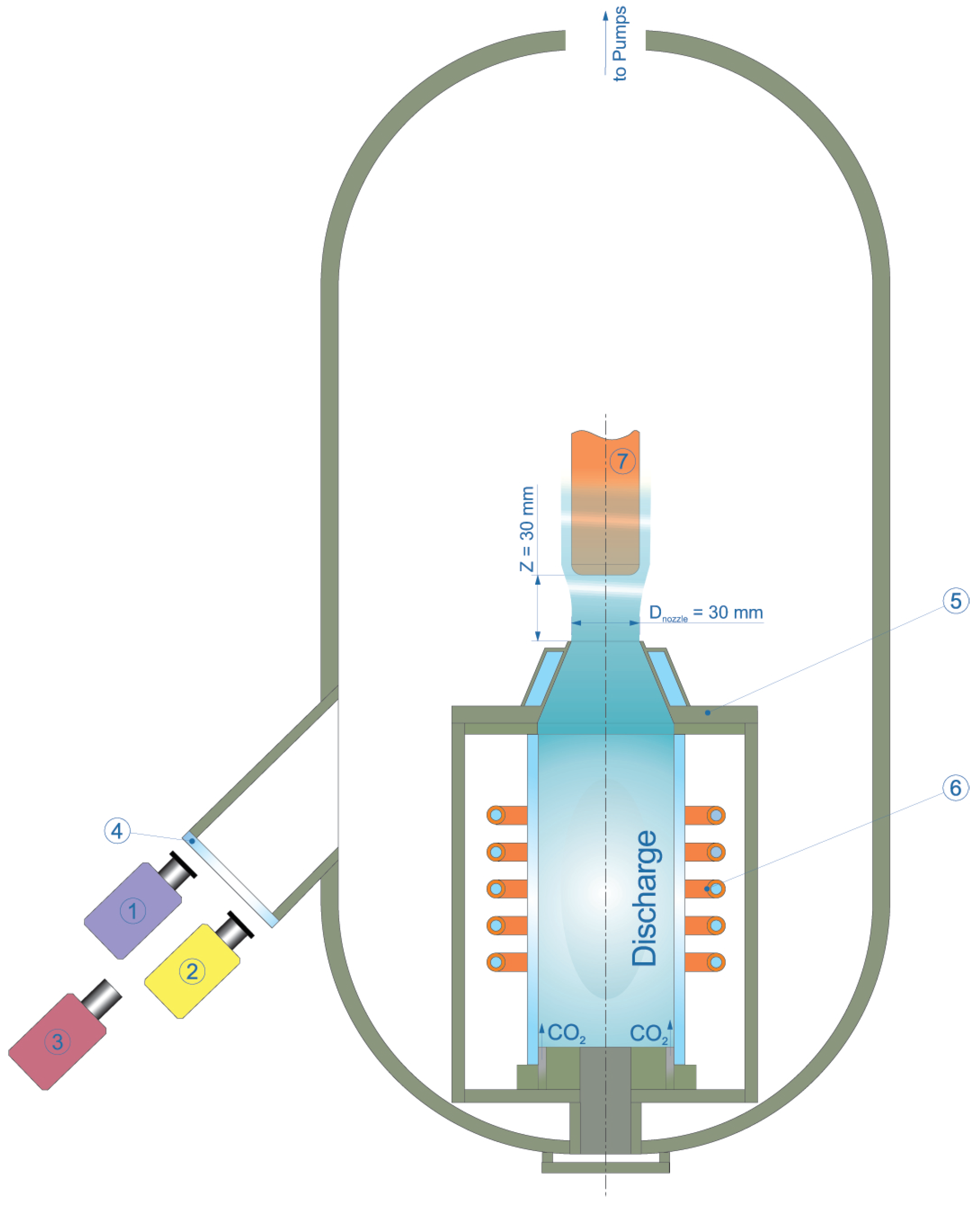
The HfB2-30vol.%SiC ceramic material was prepared using the reaction hot pressing method described in [30,31,32], as the use of the reaction sintering technique allows for a slightly lower consolidation temperature [22,33,34,35,36]. Briefly, the synthesis of the initial HfB2-SiO2-C powder was carried out using sol-gel technology and its further hot pressing was performed using a hot press model HP20-3560-20 (Thermal Technology Inc., Minden, NV, USA) at a temperature of 1800 °C (heating rate 10°/min) and a uniaxial pressure of 30 MPa in an argon atmosphere; the dwell time was 15 min. The resulting cylindrical sample had a diameter of 15.1 mm, a thickness of 3.1 mm, and a density of 96.8 ±. In total, 0.7% was used to study its behavior in a supersonic flow of pure dissociated CO2.

2.2. Test Facility

The oxidation resistance and heat transfer of the sample were studied in a high-enthalpy supersonic carbon dioxide jet at the VGU-4 ICP facility [37] using a 30 mm diameter sonic nozzle. A sketch of the test configuration is shown in Figure 1. General parameters of the VGU-4 ICP facility are given in Table 1. The average temperature of the heated sample surface was measured with a Mikron M700S spectral-ratio pyrometer (Mikron Infrared Inc., Oakland, CA, USA) and an AST Swift 350 PL brightness pyrometer (Accurate Sensors Technologies Ltd., Udaipur, India). The diameter of the sighting area was ∼5 mm in the central part of the sample. The temperature distribution on the sample surface was studied using a Tandem VS-415U thermal imager (OOO “PK ELGORA”, Korolev, Moscow region, Russia). The readings of the Tandem VS-415U thermal imager and AST Swift 350 PL brightness pyrometer were adjusted to account for the expected spectral emissivity ε λ of the surface (0.6 for both spectral ranges) and the transmittance of the KCl view port (0.93). During the analysis of the thermal imager data the surface temperatures were corrected to the real ε λ values obtained from comparison with spectral-ratio pyrometer measurements. The Mikron M770S spectral-ratio pyrometer does not require an emissivity setting (assuming that the spectral emissivity of the surface does not change at the two close operating wavelengths near 1 µm [38]). The details of the pyrometry system are summarized in Table 2 and Figure 2. The CO2 flow rate was controlled by a Bronkhorst MV-306 flowmeter (Bronkhorst High-Tech BV, Ruurlo, The Netherlands). The pressure in the test chamber was monitored by a pressure transducer Elemer AIR-20/M2-DA (NPP “Elemer”, Moscow, Russia). The geometry of the holder in which the sample was fixed is described in detail in [29,39]. The sample was installed on the friction in the socket of the water-cooled calorimeter; the gap was filled with a flexible thermal insulation based on SiC and carbon fibre in order to minimize heat loss into the water-cooled holder. The cold wall (CW) heat flux in the supersonic CO2 plasma jet was measured with a copper water-cooled calorimetric probe [40]. The steady-state calorimetric probe was installed in a water-cooled cylindrical holder measuring 30 mm in diameter with a flat front surface. The heat-absorbing surface of the probe was 13.8 mm in diameter. The mass flow rate of the cooling water was measured with a Bronkhorst ES-FLOW ultrasonic liquid flow meter (Bronkhorst High-Tech BV, Ruurlo, The Netherlands). The temperature increase of the water was measured with a chromel–alumel differential thermocouple. Heat flux measurements are estimated to have an uncertainty of 5–10% [40,41].

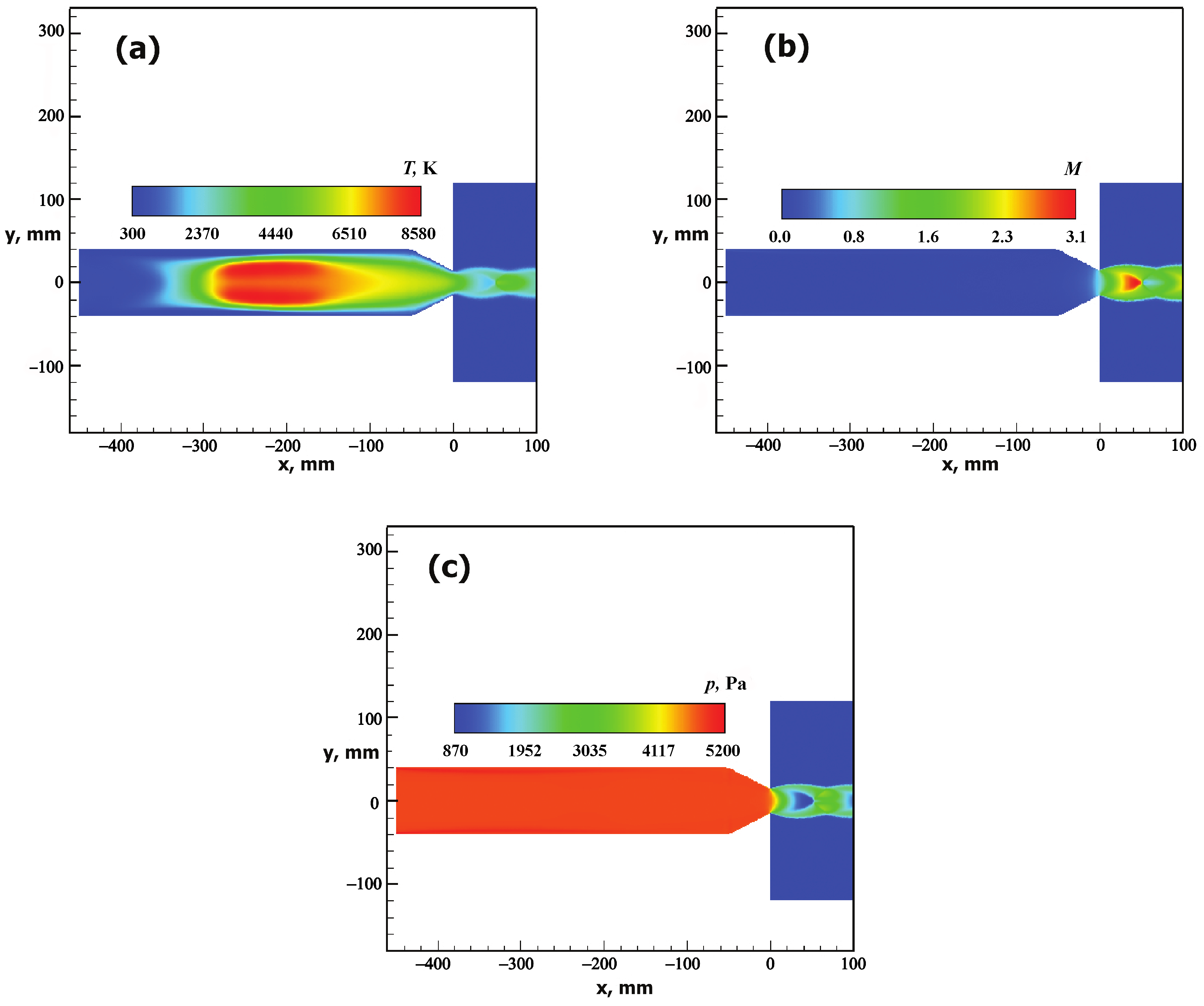
2.3. Numerical Simulation

Numerical simulation of the carbon dioxide plasma flow in the facility’s cylindrical discharge channel and in the underexpanded jet emanating from the conical sonic nozzle was performed using the software package for numerical integration of the Navier–Stokes equations [42]. The details of the calculation method are described in [43]. The mixture of CO2 was considered as an ideal mixture of perfect gases, in which chemical reactions and ionization reactions can proceed. Thermodynamic and thermochemical data for the gas components are taken from [44]. The constants of chemical reactions proceeding in the high-temperature CO2 mixture are taken from [45,46,47,48].

2.4. Material Investigation

X-ray patterns of the obtained HfB2-30vol.%SiC ceramic material before and after exposure to supersonic carbon dioxide flow were recorded on a Bruker D8 Advance X-ray diffractometer (CuK α radiation, and 0.02° resolution with signal accumulation in the point for 0.3 s, Bruker, Billerica, MA, USA). X-ray phase analysis was carried out using MATCH!—Phase Identification from Powder Diffraction, Version 3.8.0.137 (Crystal Impact, Bonn, Germany), Crystallography Open Database (COD). Crystalline lattice parameters and average crystallite size were calculated using full-field analysis in the TOPAS software (Version 4.2). Raman spectra were recorded on a Confotec NR500 Raman spectrometer (100 × 0.95 objective, 532 nm laser; grating 600; SOL Instruments, Augsburg, Germany). The power on the sample was 20 mW. The signal accumulation time was 60 s. The surface and chipping of ultrahigh-temperature HfB2-SiC ceramic samples after exposure to a supersonic CO2 plasma was investigated by scanning electron microscopy (SEM) on a three-beam NVision 40 (Carl Zeiss, Oberkochen, Germany) work station with accelerating voltages of 1 and 20 kV using secondary electron (SE2) and energy-selective backscattering (ESB), respectively. The elemental composition of the regions was determined using an Oxford Instruments energy-dispersive analysis device (EDX, Oxford, UK; accelerating voltage, 20 kV).

3. Test Conditions

The test was performed in supersonic high-enthalpy carbon dioxide jet flowing from a water-cooled conical nozzle with an outlet diameter of D n o z z l e = 30 mm at a pressure in the test chamber p c h = 870 Pa, HF-generator anode power N a p = 45 kW, and gas mass flow rate G = 2.4 g/s. The distance from the nozzle outlet to the ceramic sample was 30 mm.
The cold wall heat flux value measured under the same test conditions at the same distance from the nozzle outlet was q c w = 249 W/cm2.
The main flow parameters and gas composition at the nozzle outlet obtained by numerical simulation for the test conditions are shown in Table 3 and Table 4, respectively. These values were calculated at the nozzle symmetry axis. The distribution of flow parameters is shown in Figure 3.
The HfB2-30vol.%SiC ceramic sample was immersed in the high-enthalpy jet when stable test conditions were achieved. Under these conditions, the sample was held until the end of the experiment; the total exposure time was 5 min (300 s).

4. Results and Discussion

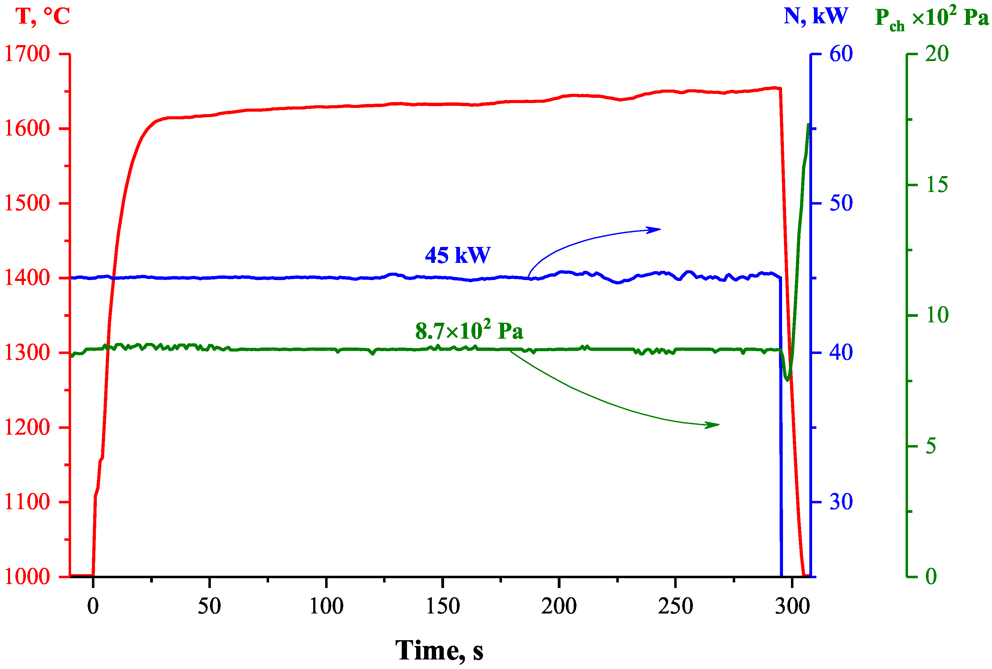
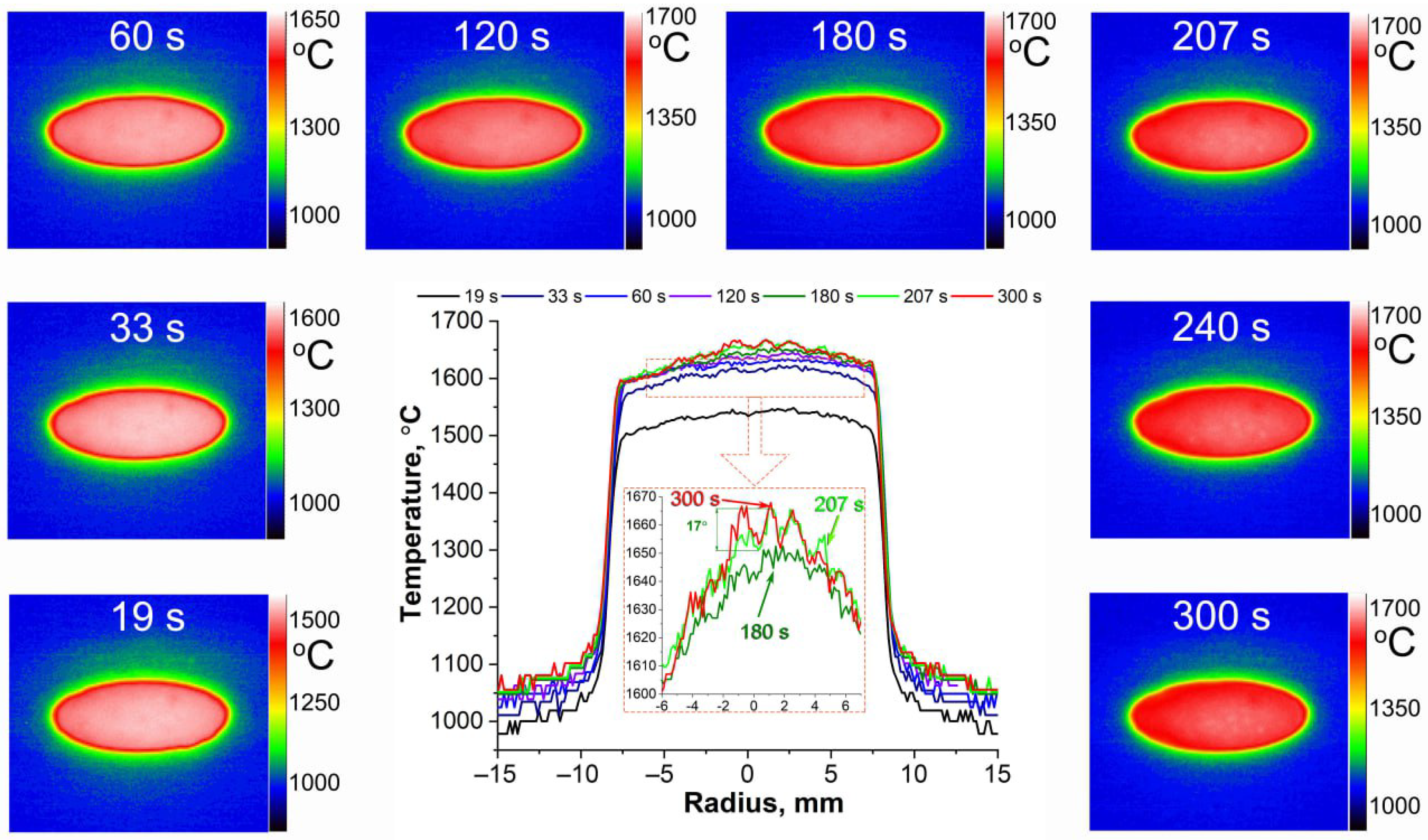
4.1. Heat Transfer and Behavior of HfB2-SiC Material under Exposure to Supersonic Flow of Dissociated CO2

After the HfB2-30vol.%SiC ceramic sample, fixed in a water-cooled holder, was immersed in a supersonic flow of dissociated CO2, the average surface temperature measured by a spectral ratio pyrometer reached 1615 °C in 30 s (Figure 4). It then increased systematically until the end of the test with a surface heating rate of 8.4 °/min. The surface temperature at the end of the exposure (at the 300th second) was 1657 °C.
Thermal imager and brightness pyrometer temperature readings were originally collected for the preset surface spectral emissivity ε λ = 0.6 in the corresponding spectral ranges ( λ 1 and λ 2 , respectively), which are different for these instruments (see Table 2). The average spectral emissivities in the spectral ranges from 0.8 to 1.0 µm ( λ 1 ) and from 2.0 to 2.6 µm ( λ 2 ) were evaluated by comparison with the spectral-ratio pyrometer readings as a reference (Figure 5). The idea and details of such in situ emissivity measurements are described in [23,49,50,51]. Spectral emissivities for both spectral ranges decrease during exposure from a value of 0.64–0.67 to 0.41 due to surface oxidation.
The heat flux to the HfB2-30% SiC sample surface in the steady-state regime can be estimated from the heat balance equation:
q w = q c o n d + ε t · σ · T 4 .
In this equation, q w is the unknown heat flux, q c o n d is the energy loss by heat conduction into the interior (which is measured by a calorimeter installed in the water-cooled sample holder), ε t is the total emissivity of the surface, σ is the Stefan–Boltzmann constant, and T is the surface temperature according to the data of the spectral-ratio pyrometer (in K).
As can be seen in Figure 5, the spectral emissivities for the two independent spectral ranges ( λ 1 and λ 2 ) are almost equal after the 30th second of the experiment (in the quasi-steady-state regime when the surface temperature changed slowly). This allows us to make the assumption that the sample surface is close to gray body ( ε t = ε λ ), at least in the near-IR range. According to Wien’s law, the maximum radiation intensity for a surface temperature of ∼1900 K corresponds to a wavelength of about 1.5 µm. In this case, we can use the obtained spectral emissivity values instead of the total emissivity in Equation (1) and estimate the average heat flux (from the 30th to the 300th second of the experiment) for the steady state regime as q w = 112 W/cm2. This value is lower than the cold wall heat flux q c w = 249 W/cm2 measured under the same test conditions. Some errors in the method may be due to the difference between the real surface of the HfB2-30% SiC ceramic material and the gray body model. As shown in [52], the emissivity of HfB2-based ceramics can actually depend on the wavelength range. But even for a black body ( ε t = 1 ), the heat flux calculated from Equation (1) does not exceed 160 W/cm2. The difference in heat flux to the surface of the ceramic sample and the cold copper surface under the same test conditions is mainly due to the lower catalytic properties of the oxidized HfB2-30% SiC material with respect to heterogeneous recombination of atomic oxygen and partly due to the temperature factor. This effect must be taken into account when analyzing the results of material testing and designing thermal protection systems for descent vehicles.
Analysis of the thermal imager data showed (Figure 6) that the temperature distribution over the surface was as uniform as possible from the first seconds of exposure due to the good thermal conductivity. During the first three minutes, the temperature difference over the entire surface did not exceed 50 °C (due to the lower temperature at the edges of the sample) and locally, at a radius of 1–2 mm, ≤5–8 °C. Approximately after the middle of the fourth minute the general temperature difference increased to ∼65–70 °C, and locally in the central region of the sample there appeared irregularities, ∼15–20 °C, which may be related to the change in microstructure of the oxidized surface of the sample. This temperature distribution was maintained until the end of the experiment.

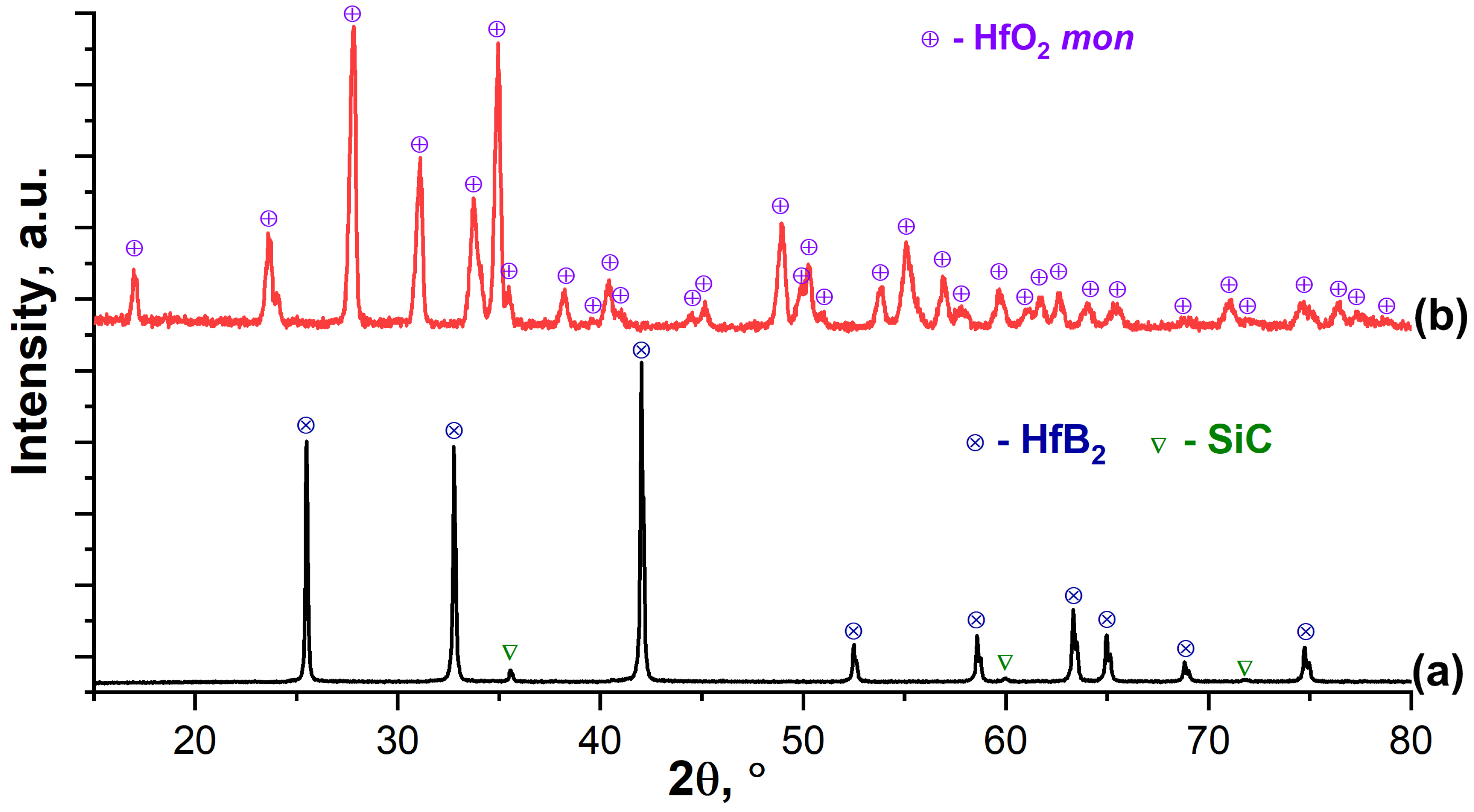
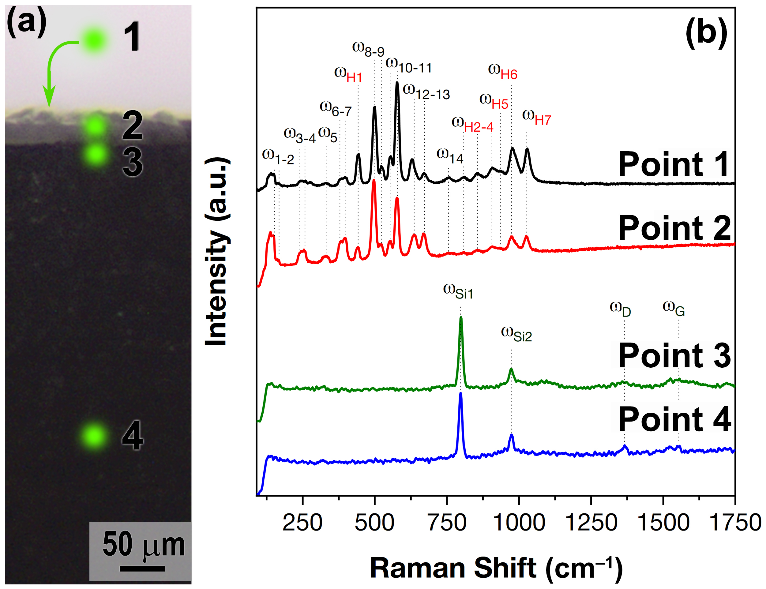
4.2. Investigation of HfB2-SiC Material after Exposure to Supersonic Flow of Dissociated CO2

The X-ray phase analysis of the oxidized surface (Figure 7) showed that, despite the relatively short exposure time of the CO2 plasma (5 min), even low intensity reflections of the initial phases of HfB2 [53] and SiC [54] occurred. All observed reflections correspond to the crystal lattice of monoclinic hafnium oxide [55]. Calculations using the Rietveld method showed that in this case HfO2 is characterized by a certain distortion of the structure, which is expressed by compression along the a and c axes (a = 5.125, b = 5.189, c = 5.302 Å, β = 99.212 compared to the literature a = 5.150, b = 5.185, c = 5.342 Å, β = 98.948 [55]). The artificial addition of the HfSiO4 phase (the content of which, according to the calculations, cannot exceed 12%) does not lead to a change in the calculated parameters towards the reference value.
The SEM study of the microstructure of the surface formed as a result of the oxidation of the starting ceramic material HfB2-30vol.%SiC by a high-speed flow of dissociated CO2 showed (Figure 8) that it has a rather high roughness, not only due to the oxidation of HfB2, but also to the formation of strongly protruding bubbles with a diameter of mainly ∼7–20 µm. The latter are probably formed during the removal of the gaseous oxidation product (CO) and during the rapid evaporation of borosilicate glass components at elevated temperatures. Their formation on the surface can be related to the brighter areas observed in the middle of the fourth minute of exposure in the thermal images. These bubbles appear to be brittle and easily destroyed (Figure 8a–d), with a wall thickness of ∼100–350 nm. The study in the average atomic number contrast mode (ESD detector, Figure 8b,d), allowed us to determine that the outer surface is mainly HfO2 and the inner surface (as can be seen in Figure 8b,d by the bases and wall fragments of the destroyed bubbles) is lined with silicate melt. The latter is a mobile phase at the experimental temperature ∼1620–1655 °C, HfO2 particles are dispersed in it, and due to the melt it is possible to move them from the near surface regions and along the surface. Interestingly, X2c,d micrographs at the base of the collapsed bubble show inclusions of oriented, vertically elongated HfO2 particles (diameter ∼150–550 nm) in the silicate melt matrix, illustrating the “solid pillars, liquid roof” model once proposed by Li et al. [56] in a situation after the “liquid roof” evaporation had started from the surface [57,58,59]. Elemental analysis using EDX confirmed that on the oxidized ceramic surface between the bubbles, only HfO2 was localized (silicon was not found, probably because its content is below the detection limit of the method), hafnium dioxide predominated on the bubble surface (the n(Hf):n(Si) ratio is 9:1), and when the surface area of 440 × 585 µm was scanned, the n(Hf):n(Si) ratio decreased to 4:1 due to the destruction of the bubbles and the exposure of their internal composition. Analysis of the microstructure of the bubbles preserved on the oxidized surface of the ceramic material has shown (Figure 8e,f) that there are 40–80 nm pores between the flat aggregates of the HfO2 particles, probably bound from the inside by silicate melt. In general, the microstructure of the oxidized surface is close to that previously observed in our studies of the interaction of HfB2-SiC-based materials with supersonic flows of dissociated CO2 [29] and air [31,32,60,61]. However, in the present experiment, a greater number of preserved bubbles and their remnants are present on the surface where silicate glass is preserved, whereas in previous work, due to higher thermal stress and longer exposure times, only craters were recorded at their rupture sites.
Analysis of the microstructure of the HfB2-30vol%SiC ceramic chip after thermochemical treatment (Figure 9) showed that a rather thin oxidized region of 22 ± 4 µm thickness was formed close to the surface. At the same time, a thin HfO2 film less than 300–500 nm thick is present on the surface itself, under which a layer of HfO2 particles distributed in the silicate glass is observed. However, the porous layer depleted of SiC commonly observed below, which would be formed as a result of the oxidation of SiC by an active mechanism under a layer of silicate melt under conditions of reduced O2 concentration [56], was not found in this case. This is also confirmed by the mapping of the distribution of the elements Si, O, and C (the latter is given tentatively due to the low accuracy of its determination by the EDX method) in Figure 10: the superimposition of the microphotography with increased acceleration voltage (20 kV) to increase the contrast and the corresponding distributions of silicon and oxygen show that the upper oxidized layer passes directly into the initial material with normal silicon content.
Local EDX analysis in the upper third of the HfO2-SiO2 layer thickness showed that hafnium oxide clearly predominates closer to the surface (the ratio of n(Hf):n(Si) is ∼6), while closer to the end of the oxide layer the silicon content increases (n(Hf):n(Si) is ∼3). At the same time, directly below the HfO2-SiO2 layer, according to the EDX data, the n(Hf):n(Si) ratio is practically no different from that given and experimentally determined for the bulk part of the HfB2-30vol.%SiC sample. Only a slight increase in defect/porosity can be observed at the interface between the unoxidized material and the HfO2-SiO2 layer (Figure 9c,d) with a thickness of less than 1 µm. This structure of the oxidized region is probably due to the fact that the exposure to a high-enthalpy CO2 flow was stopped at the initial stage of oxidation of the HfB2-30vol.%SiC ceramics, since for a similar material composition in a previous experiment, characterized by a higher heat flux and exposure duration, the formation of a conventional multilayer structure was observed [29], including a depleted SiC layer.
To confirm this, Raman spectra were recorded from some surface and cracked areas of the HfB2-30vol.%SiC ceramic sample after exposure to the supersonic flow of dissociated CO2 (Figure 11): point 1 corresponds to the surface in the central region of the sample and points 2–4 correspond to different cracked areas. As can be seen, the Raman spectra at points 1 and 2 (the oxidized surface and the one closest to the surface crack of the sample in the region of the HfO2-SiO2 layer, respectively) have the same set of bands. A detailed analysis of these spectra reveals 14 characteristic bands ( ω 1 ω 14 at 150, 165, 241, 257, 332, 381, 398, 499, 525, 554, 578, 631, 671 and 756 cm−1) of different intensities belonging to the Ag and Bg modes of the monoclinic phase of HfO2, in good agreement with the literature data [62,63,64,65]. In addition to the monoclinic HfO2 phase, seven characteristic Raman modes of the ω H 1 ω H 7 phase of hafnone (HfSiO4) are detected at these sites at 442, 808, 854, 907, 937, 976 and 1028 cm−1, which are also in good agreement with the available literature data [66,67,68,69].
For points 3 and 4 (Figure 11b), located just below the oxide layer and in the apparently unoxidized volume of the HfB2-30vol.%SiC ceramics, the Raman spectra are almost identical: only two intense modes ω S i 1 and ω S i 2 at 798 and 973 cm−1, belonging to silicon carbide (most likely polytype 3C) [70,71], as well as two very weak and faint modes ω D and ω G at 1380 and 1635 cm−1, which are characteristic bands of different forms of carbon, probably residual carbon after in situ SiC production during the manufacture of HfB2-30vol.%SiC ceramics.
Thus, the set of methods confirms the fact that as a result of the short-term (5 min) thermochemical influence of the supersonic flow of dissociated CO2 at the selected parameters of the experiment, it is possible to observe the initial stage of oxidation of the HfB2-30vol.%SiC high-temperature ceramic, at which the formation of the depleted SiC layer has not yet occurred. This may be due to the fact that the HfO2-SiO2 surface layer formed during oxidation of the HfB2-SiC composite was not yet sufficiently tight at the time the experiment was completed to create the low oxygen content required for active oxidation of SiC [57,72]. For example, there may have been pores in this layer that promote oxygen diffusion into the material volume, or there may have been HfO2 particles that act as a bridge for oxygen due to their ionic conductivity, or the thickness of the SiO2 melt layer of the order of 20–25 µm, are insufficient to form an oxygen content gradient. The present study of the peculiarities of the oxidation process of ultrahigh-temperature ceramics under the influence of a high-velocity flow of dissociated CO2 is one of the first steps indicating the important need to continue systematic studies of the degradation process of such materials in gaseous media that differ significantly in composition from the Earth’s atmosphere.

5. Conclusions

Our team continues to study the heat transfer and behavior of UHTC materials when exposed to high enthalpy molecular gas plasma flows.
It is experimentally shown that as a result of relatively short-term exposure (within 5 min) on ultrahigh-temperature ceramics of composition HfB2-30vol.%SiC of supersonic flow of dissociated CO2 on the surface a temperature between 1615–1655 °C is established and there is a tendency towards insignificant growth at the rate of 8°/min. Under the experimental conditions chosen, it is likely that the oxide layer began to form on the surface of the material, since the analytical methods used (SEM with different detectors and accelerating voltages, optical microscopy and Raman spectroscopy) did not allow us to detect the formation of a porous SiC-depleted region under the HfO2-SiO2 surface oxide layer. With some degree of doubt, we can note the existence of a very thin region (less than 1 µm thick, according to SEM data) of increased porosity/defectivity just below the localization of the layer of hafnium oxide particles distributed in the silicate glass, which may be caused not only by the onset of active oxidation of SiC with the formation of SiO/CO, but also by the detachment of HfO2-SiO2 from non-oxidized HfB2-SiC due to the differences in thermal expansion coefficients revealed by the abrupt cooling of the sample.
Ceramic sample surface spectral emissivities obtained during the experiment for two independent spectral ranges were almost equal. This result allowed us to use the gray body model assumption for radiative heat transfer analysis. However, additional emissivity studies in specialized facilities are still appropriate and important. The estimated heat flux to the surface of the heated UHTC sample was lower than that measured by the cold copper probe. This fact confirms that catalytic properties of the surface and wall temperature should be taken into account when modeling heat transfer. Numerical flow simulations allow detailed analysis of test conditions.
In general, it is necessary to note the usefulness of a systematic study of the peculiarities of the behavior of ultrahigh-temperature ZrB2/HfB2-SiC ceramics, including those doped with various components, under the influence of high-speed gas flows containing CO2. Our future plans also include studies of UHTC materials in a mixture of methane and nitrogen, in pure nitrogen, in a mixture of nitrogen and carbon dioxide, and under additional radiative heating.
This has potential application for material selection in the development of advanced space exploration vehicles.

Author Contributions

Conceptualization, A.V.C., E.P.S.; methodology, E.P.S., A.F.K., A.N.S., V.I.S., N.G.S. and N.T.K.; investigation, A.V.C., E.P.S., M.A.K., V.I.S., I.V.L., S.S.G., M.Y.Y., A.S.L., I.A.N., A.S.M. and N.P.S.; writing—original draft preparation, A.V.C. and E.P.S.; writing—review and editing, M.A.K., V.I.S. and A.F.K.; visualization, E.P.S., N.P.S., S.S.G. and A.V.C.; supervision, A.F.K., N.G.S. and N.T.K.; project administration, A.V.C. and E.P.S.; funding acquisition, A.V.C. All authors have read and agreed to the published version of the manuscript.

Funding

The research was supported by the Russian Science Foundation (project No. 22-79-10083, https://rscf.ru/en/project/22-79-10083/ (accessed on 16 April 2024)).

Institutional Review Board Statement

Not applicable.

Informed Consent Statement

Not applicable.

Data Availability Statement

Data are contained within the article.

Acknowledgments

The experiments were carried out at HF-plasmatron VGU-4 (IPMech RAS Research Resource Center).

Conflicts of Interest

The authors declare no conflicts of interest.

Abbreviations

The following abbreviations are used in this manuscript:
TPSThermal protection system
UHTCUltrahigh-temperature ceramic material
ICPInductively Coupled Plasma
CWCold wall
CODCrystallography Open Database
SEMScanning electron microscopy
SE2Secondary electron
ESBEnergy-selective backscattered
HFHigh Frequency

References

  1. Laub, B.; Venkatapathy, E. Thermal protection system technology and facility needs for demanding future planetary missions. In Proceedings of the Planetary Probe Atmospheric Entry and Descent Trajectory Analysis and Science, Lisbon, Portugal, 6–9 October 2003; Volume 544, pp. 239–247. [Google Scholar]
  2. Swanson, T.; Motil, B.; Chandler, F.; Bruce, W.; Dinsmore, C.; Kostyk, C.; Lysek, M.; Rickman, S.; Stephan, R. NASA Technology Roadmaps TA 14: Thermal Management Systems; National Aeronautics and Space Administration: Washington, DC, USA, 2015; Volume 21, p. 2019. [Google Scholar]
  3. Venkatapathy, E.; Ellerby, D.; Gage, P.; Prabhu, D.; Gasch, M.; Kazemba, C.; Kellerman, C.; Langston, S.; Libben, B.; Mahzari, M.; et al. Entry system technology readiness for ice-giant probe missions. Space Sci. Rev. 2020, 216, 22. [Google Scholar] [CrossRef]
  4. Simonenko, E.; Sevast’Yanov, D.; Simonenko, N.; Sevast’Yanov, V.; Kuznetsov, N. Promising ultra-high-temperature ceramic materials for aerospace applications. Russ. J. Inorg. Chem. 2013, 58, 1669–1693. [Google Scholar] [CrossRef]
  5. Bianco, G.; Nisar, A.; Zhang, C.; Boesl, B.; Agarwal, A. A critical analysis of the parameters affecting the oxidation behavior of ultra-high-temperature diboride ceramics. J. Am. Ceram. Soc. 2022, 105, 1939–1953. [Google Scholar] [CrossRef]
  6. Han, T.; Huang, J.; Sant, G.; Neithalath, N.; Kumar, A. Predicting mechanical properties of ultrahigh temperature ceramics using machine learning. J. Am. Ceram. Soc. 2022, 105, 6851–6863. [Google Scholar] [CrossRef]
  7. Jin, X.; He, R.; Zhang, X.; Hu, P. Ablation behavior of ZrB2–SiC sharp leading edges. J. Alloys Compd. 2013, 566, 125–130. [Google Scholar] [CrossRef]
  8. Jin, H.; Zhang, S.; Hao, Y.; Yang, Y.; Xu, C. Mechanical properties and fracture behavior of ultrahigh temperature ceramics at ultrahigh temperatures. Ceram. Int. 2023, 49, 28532. [Google Scholar] [CrossRef]
  9. Nisar, A.; Hassan, R.; Agarwal, A.; Balani, K. Ultra-high temperature ceramics: Aspiration to overcome challenges in thermal protection systems. Ceram. Int. 2022, 48, 8852–8881. [Google Scholar] [CrossRef]
  10. Zhao, K.; Ye, F.; Cheng, L.; Yang, J.; Chen, X. An Overview of Ultra-High Temperature Ceramic for Thermal Insulation: Structure and Composition Design with Thermal Conductivity Regulation. J. Eur. Ceram. Soc. 2023, 43, 7241–7262. [Google Scholar] [CrossRef]
  11. Meng, J.; Fang, H.; Wang, H.; Wu, Y.; Wei, C.; Li, S.; Geng, X.; Li, X.; Zhang, J.; Wen, G.; et al. Effects of refractory metal additives on diboride-based ultra-high temperature ceramics: A review. Int. J. Appl. Ceram. Technol. 2023, 20, 1350–1370. [Google Scholar] [CrossRef]
  12. Sonber, J.; Murthy, T.C.; Majumdar, S.; Kain, V. Processing of ZrB-and HfB-Based Ultra-High Temperature Ceramic Materials: A Review. Mater. Perform. Charact. 2021, 10, 89–121. [Google Scholar] [CrossRef]
  13. Savino, R.; Criscuolo, L.; Di Martino, G.D.; Mungiguerra, S. Aero-thermo-chemical characterization of ultra-high-temperature ceramics for aerospace applications. J. Eur. Ceram. Soc. 2018, 38, 2937–2953. [Google Scholar] [CrossRef]
  14. Silvestroni, L.; Mungiguerra, S.; Sciti, D.; Di Martino, G.D.; Savino, R. Effect of hypersonic flow chemical composition on the oxidation behavior of a super-strong UHTC. Corros. Sci. 2019, 159, 108125. [Google Scholar] [CrossRef]
  15. Golla, B.R.; Mukhopadhyay, A.; Basu, B.; Thimmappa, S.K. Review on ultra-high temperature boride ceramics. Prog. Mater. Sci. 2020, 111, 100651. [Google Scholar] [CrossRef]
  16. Kováčová, Z.; Orovčík, L.; Sedláček, J.; Bača, L.; Dobročka, E.; Kitzmantel, M.; Neubauer, E. The effect of YB4 addition in ZrB2-SiC composites on the mechanical properties and oxidation performance tested up to 2000 °C. J. Eur. Ceram. Soc. 2020, 40, 3829–3843. [Google Scholar] [CrossRef]
  17. Mungiguerra, S.; Cecere, A.; Savino, R.; Saraga, F.; Monteverde, F.; Sciti, D. Improved aero-thermal resistance capabilities of ZrB2-based ceramics in hypersonic environment for increasing SiC content. Corros. Sci. 2021, 178, 109067. [Google Scholar] [CrossRef]
  18. Squire, T.H.; Marschall, J. Material property requirements for analysis and design of UHTC components in hypersonic applications. J. Eur. Ceram. Soc. 2010, 30, 2239–2251. [Google Scholar] [CrossRef]
  19. Monteverde, F.; Savino, R. ZrB2–SiC sharp leading edges in high enthalpy supersonic flows. J. Am. Ceram. Soc. 2012, 95, 2282–2289. [Google Scholar] [CrossRef]
  20. Astapov, A.; Zhestkov, B.; Senyuev, I.; Shtapov, V. Methodology of studying high-velocity plasma flow impact on high-temperature materials. AIP Conf. Proc. 2023, 2549, 210009. [Google Scholar]
  21. Kolesnikov, A.; Kuznetsov, N.; Muravyeva, T.; Nagornov, I.; Sakharov, V.; Sevastyanov, V.; Simonenko, E.; Simonenko, N.; Chaplygin, A.; Shcherbakova, O. Investigation of Heat Transfer to HfB2-SiC-Based Ceramics in Underexpanded Dissociated-Nitrogen Flows and Analysis of the Surface. Fluid Dyn. 2022, 57, 513–523. [Google Scholar] [CrossRef]
  22. Simonenko, E.P.; Simonenko, N.P.; Kolesnikov, A.F.; Chaplygin, A.V.; Lysenkov, A.S.; Nagornov, I.A.; Mokrushin, A.S.; Kuznetsov, N.T. Investigation of the Effect of Supersonic Flow of Dissociated Nitrogen on ZrB2–HfB2–SiC Ceramics Doped with 10 vol.% Carbon Nanotubes. Materials 2022, 15, 8507. [Google Scholar] [CrossRef] [PubMed]
  23. Monteverde, F.; Savino, R. Stability of ultra-high-temperature ZrB2–SiC ceramics under simulated atmospheric re-entry conditions. J. Eur. Ceram. Soc. 2007, 27, 4797–4805. [Google Scholar] [CrossRef]
  24. Savino, R.; Fumo, M.D.S.; Silvestroni, L.; Sciti, D. Arc-jet testing on HfB2 and HfC-based ultra-high temperature ceramic materials. J. Eur. Ceram. Soc. 2008, 28, 1899–1907. [Google Scholar] [CrossRef]
  25. Alosime, E.M.; Alsuhybani, M.S.; Almeataq, M.S. The oxidation behavior of ZrB2-SiC ceramic composites fabricated by plasma spray process. Materials 2021, 14, 392. [Google Scholar] [CrossRef] [PubMed]
  26. Hash, B. Planetary Mission Entry Vehicles Quick Reference Guide, Technical Report, version 4.1; NASA: Washington, DC, USA, 2003. [Google Scholar]
  27. Girija, A.P.; Lu, Y.; Saikia, S.J. Feasibility and mass-benefit analysis of aerocapture for missions to Venus. J. Spacecr. Rocket. 2020, 57, 58–73. [Google Scholar] [CrossRef]
  28. Dutta, S.; Smith, B.; Prabhu, D.; Venkatapathy, E. Mission sizing and trade studies for low ballistic coefficient entry systems to Venus. In Proceedings of the 2012 IEEE Aerospace Conference, Big Sky, MT, USA, 3–10 March 2012; pp. 1–14. [Google Scholar]
  29. Simonenko, E.P.; Kolesnikov, A.F.; Chaplygin, A.V.; Kotov, M.A.; Yakimov, M.Y.; Lukomskii, I.V.; Galkin, S.S.; Shemyakin, A.N.; Solovyov, N.G.; Lysenkov, A.S.; et al. Oxidation of Ceramic Materials Based on HfB2-SiC under the Influence of Supersonic CO2 Jets and Additional Laser Heating. Int. J. Mol. Sci. 2023, 24, 13634. [Google Scholar] [CrossRef] [PubMed]
  30. Simonenko, E.; Simonenko, N.; Papynov, E.; Gridasova, E.; Sevastyanov, V.; Kuznetsov, N. Production of HfB2–SiC (10–65 vol% SiC) ultra-high-temperature ceramics by hot pressing of HfB2–(SiO2–C) composite powder synthesized by the sol–gel method. Russ. J. Inorg. Chem. 2018, 63, 1–15. [Google Scholar] [CrossRef]
  31. Simonenko, E.P.; Simonenko, N.P.; Gordeev, A.N.; Kolesnikov, A.F.; Sevastyanov, V.G.; Kuznetsov, N.T. Behavior of HfB2–30 vol% SiC UHTC obtained by sol–gel approach in the supersonic airflow. J. Sol-Gel Sci. Technol. 2019, 92, 386–397. [Google Scholar] [CrossRef]
  32. Simonenko, E.P.; Simonenko, N.P.; Gordeev, A.N.; Kolesnikov, A.F.; Lysenkov, A.S.; Nagornov, I.A.; Sevastyanov, V.G.; Kuznetsov, N.T. The effects of subsonic and supersonic dissociated air flow on the surface of ultra-high-temperature HfB2-30 vol% SiC ceramics obtained using the sol-gel method. J. Eur. Ceram. Soc. 2020, 40, 1093–1102. [Google Scholar] [CrossRef]
  33. Simonenko, E.; Simonenko, N.; Kolesnikov, A.; Chaplygin, A.; Sakharov, V.; Lysenkov, A.; Nagornov, I.; Kuznetsov, N. Effect of 2 vol% Graphene Additive on Heat Transfer of Ceramic Material in Underexpanded Jets of Dissociated Air. Russ. J. Inorg. Chem. 2022, 67, 2050–2061. [Google Scholar] [CrossRef]
  34. Shapkin, N.; Papynov, E.; Shichalin, O.; Buravlev, I.Y.; Simonenko, E.; Simonenko, N.; Zavjalov, A.; Belov, A.; Portnyagin, A.; Gerasimenko, A.; et al. Spark plasma sintering-reactive synthesis of SiC and SiC–HfB2 ceramics based on natural renewable raw materials. Russ. J. Inorg. Chem. 2021, 66, 629–637. [Google Scholar] [CrossRef]
  35. Simonenko, E.; Simonenko, N.; Kolesnikov, A.; Chaplygin, A.; Lysenkov, A.; Nagornov, I.; Sevastyanov, V.; Kuznetsov, N. Modification of HfB2–30% SiC UHTC with Graphene (1 Vol%) and Its Influence on the Behavior in a Supersonic Air Jet. Russ. J. Inorg. Chem. 2021, 66, 1405–1415. [Google Scholar] [CrossRef]
  36. Simonenko, E.P.; Simonenko, N.P.; Kolesnikov, A.F.; Chaplygin, A.V.; Lysenkov, A.S.; Nagornov, I.A.; Simonenko, T.L.; Gubin, S.P.; Sevastyanov, V.G.; Kuznetsov, N.T. Oxidation of graphene-modified HfB2-SiC ceramics by supersonic dissociated air flow. J. Eur. Ceram. Soc. 2022, 42, 30–42. [Google Scholar] [CrossRef]
  37. Gordeev, A. Overview of Characteristics and Experiments in IPM Plasmatrons. VKI, RTO AVT/VKI Special Course on Measurement Techniques for High Enthalpy Plasma Flows, 1999. Available online: https://apps.dtic.mil/sti/citations/ADP010736 (accessed on 16 April 2024).
  38. Pyatt, E. Some consideration of the errors of brightness and two-colour types of spectral radiation pyrometer. Br. J. Appl. Phys. 1954, 5, 264. [Google Scholar] [CrossRef]
  39. Kolesnikov, A.; Lukomskii, I.; Sakharov, V.; Chaplygin, A. Experimental and numerical modeling of heat transfer to graphite surface in underexpanded dissociated-nitrogen jets. Fluid Dyn. 2021, 56, 897–905. [Google Scholar] [CrossRef]
  40. Gordeev, A.; Kolesnikov, A.; Yakushin, M. Effect of surface catalytic activity on nonequilibrium heat transfer in a subsonic jet of dissociated nitrogen. Fluid Dyn. 1985, 20, 478–484. [Google Scholar] [CrossRef]
  41. Sanson, F.; Villedieu, N.; Panerai, F.; Chazot, O.; Congedo, P.M.; Magin, T.E. Quantification of uncertainty on the catalytic property of reusable thermal protection materials from high enthalpy experiments. Exp. Therm. Fluid Sci. 2017, 82, 414–423. [Google Scholar] [CrossRef]
  42. Afonina, N.; Gromov, V.; Sakharov, V. Hightemp technique of high temperature gas flows numerical simulation. In Proceedings of the Fifth European Symposium on Aerothermodynamics for Space Vehicles (ESA SP-563), Cologne, Germany, 8–11 November 2004; Volume 563, p. 323. [Google Scholar]
  43. Gordeev, A.N.; Kolesnikov, A.F.; Sakharov, V.I. Flow and heat transfer in underexpanded nonequilibrium jets of carbon dioxide: Experiment and numerical simulation. High Temp. 2015, 53, 272–278. [Google Scholar] [CrossRef]
  44. Gurvich, L.; Veits, I.; Medvedev, V.; Khachkuruzov, G.; Yungman, V.; Bergman, G. Thermodynamic Properties of Individual Substances: Handbook; Izd. Akademiia Nauk SSSR: Moscow, Russia, 1978. [Google Scholar]
  45. Ibragimova, L.; Smekhov, G.; Shatalov, O. Dissociation rate constants of diatomic molecules under thermal equilibrium conditions. Fluid Dyn. 1999, 34, 153–157. [Google Scholar] [CrossRef]
  46. Losev, S.; Makarov, V.; Pogosbekyan, M.Y. Model of the physico-chemical kinetics behind the front of a very intense shock wave in air. Fluid Dyn. 1995, 30, 299–309. [Google Scholar] [CrossRef]
  47. Park, C.; Howe, J.T.; Jaffe, R.L.; Candler, G.V. Review of chemical-kinetic problems of future NASA missions. II-Mars entries. J. Thermophys. Heat Transf. 1994, 8, 9–23. [Google Scholar] [CrossRef]
  48. Losev, S.; Makarov, V.; Pogosbekyan, M.J.; Shatalov, O.P.; Nikol’sky, V.S. Thermochemical Nonequilibrium Kinetic Models in Strong Shock Waves in Air. In Proceedings of the 6th AIAA/ASME Joint Thermophysics and Heat Transfer Conference, Colorado Springs, CO, USA, 20–23 June 1994. AIAA Paper. [Google Scholar]
  49. Saad, A.A.; Martinez, C.; Trice, R.W. Radiation heat transfer during hypersonic flight: A review of emissivity measurement and enhancement approaches of ultra-high temperature ceramics. Int. J. Ceram. Eng. Sci. 2023, 5, e10171. [Google Scholar] [CrossRef]
  50. Biasetto, L.; Manzolaro, M.; Andrighetto, A. Emissivity measurements of opaque gray bodies up to 2000 C by a dual-frequency pyrometer. Eur. Phys. J. A 2008, 38, 167–171. [Google Scholar] [CrossRef]
  51. Purpura, C. Methods for the Material Spectral Emissivity Evaluation by Dual-Color Pyrometer in a Hypersonic Plasma Test Facility. IEEE J. Miniaturization Air Space Syst. 2020, 2, 92–97. [Google Scholar] [CrossRef]
  52. Sani, E.; Meucci, M.; Mercatelli, L.; Jafrancesco, D.; Sans, J.L.; Silvestroni, L.; Sciti, D. Optical properties of boride ultrahigh-temperature ceramics for solar thermal absorbers. J. Photonics Energy 2014, 4, 045599. [Google Scholar] [CrossRef]
  53. Holleck, H. Legierungsverhalten von HfB2 mit uran-und übergangsmetalldiboriden. J. Nucl. Mater. 1967, 21, 14–20. [Google Scholar] [CrossRef]
  54. Wyckoff, R.W.G.; Wyckoff, R.W. Crystal Structures; Interscience Publishers: New York, NY, USA, 1963; Volume 1, pp. 85–237. [Google Scholar]
  55. Henderson, S.J.; Shebanova, O.; Hector, A.L.; McMillan, P.F.; Weller, M.T. Structural variations in pyrochlore-structured Bi2Hf2O7, Bi2Ti2O7 and Bi2Hf2-xTixO2 solid solutions as a function of composition and temperature by neutron and X-ray diffraction and Raman spectroscopy. Chem. Mater. 2007, 19, 1712–1722. [Google Scholar]
  56. Li, J.; Lenosky, T.J.; Först, C.J.; Yip, S. Thermochemical and mechanical stabilities of the oxide scale of ZrB2+ SiC and oxygen transport mechanisms. J. Am. Ceram. Soc. 2008, 91, 1475–1480. [Google Scholar] [CrossRef]
  57. Parthasarathy, T.; Rapp, R.; Opeka, M.; Cinibulk, M. Modeling oxidation kinetics of SiC-containing refractory diborides. J. Am. Ceram. Soc. 2012, 95, 338–349. [Google Scholar]
  58. Zhang, X.H.; Hu, P.; Han, J.C. Structure evolution of ZrB2–SiC during the oxidation in air. J. Mater. Res. 2008, 23, 1961–1972. [Google Scholar] [CrossRef]
  59. Eakins, E.; Jayaseelan, D.D.; Lee, W.E. Toward oxidation-resistant ZrB2-SiC ultra high temperature ceramics. Metall. Mater. Trans. A 2011, 42, 878–887. [Google Scholar] [CrossRef]
  60. Simonenko, E.; Simonenko, N.; Gordeev, A.; Kolesnikov, A.; Lysenkov, A.; Nagornov, I.; Sevast’yanov, V.; Kuznetsov, N. Oxidation of Porous HfB2–SiC Ultra-High-Temperature Ceramic Materials Rich in Silicon Carbide (65 vol%) by a Supersonic Air Flow. Russ. J. Inorg. Chem. 2020, 65, 606–615. [Google Scholar] [CrossRef]
  61. Simonenko, E.; Simonenko, N.; Gordeev, A.; Kolesnikov, A.; Papynov, E.; Shichalin, O.; Tal’skikh, K.Y.; Gridasova, E.; Avramenko, V.; Sevastyanov, V.; et al. Impact of a supersonic dissociated air flow on the surface of HfB2–30 vol% SiC UHTC produced by the Sol–Gel method. Russ. J. Inorg. Chem. 2018, 63, 1484–1493. [Google Scholar] [CrossRef]
  62. Tkachev, S.; Manghnani, M.; Niilisk, A.; Aarik, J.; Mändar, H. Raman and Brillouin scattering spectroscopy studies of atomic layer-deposited ZrO2 and HfO2 thin films. Spectrochim. Acta Part A Mol. Biomol. Spectrosc. 2005, 61, 2434–2438. [Google Scholar] [CrossRef] [PubMed]
  63. Wu, R.; Zhou, B.; Li, Q.; Jiang, Z.; Wang, W.; Ma, W.; Zhang, X. Elastic and vibrational properties of monoclinic HfO2 from first-principles study. J. Phys. D Appl. Phys. 2012, 45, 125304. [Google Scholar] [CrossRef]
  64. Zhou, B.; Shi, H.; Zhang, X.; Su, Q.; Jiang, Z. The simulated vibrational spectra of HfO2 polymorphs. J. Phys. Appl. Phys. 2014, 47, 115502. [Google Scholar] [CrossRef]
  65. Khan, M.U.; Hassan, G.; Raza, M.A.; Bae, J.H. Liquid Capacitor Based on Hafnium Oxide. Key Eng. Mater. 2019, 801, 211–216. [Google Scholar] [CrossRef]
  66. Manoun, B.; Downs, R.T.; Saxena, S.K. A high-pressure Raman spectroscopic study of hafnon, HfSiO2. Am. Mineral. 2006, 91, 1888–1892. [Google Scholar] [CrossRef]
  67. Grüneberger, A.M.; Schmidt, C.; Jahn, S.; Rhede, D.; Loges, A.; Wilke, M. Interpretation of Raman spectra of the zircon–hafnon solid solution. Eur. J. Mineral. 2016, 28, 721–733. [Google Scholar] [CrossRef]
  68. Niu, J.; Lu, Z.; Nan, S.; Wu, X.; Qin, S.; Liu, Y.; Li, W. Phase transition of hafnon, HfSiO4, at high pressure. J. Am. Ceram. Soc. 2023, 106, 6292–6300. [Google Scholar] [CrossRef]
  69. Estevenon, P.; Kaczmarek, T.; Rafiuddin, M.R.; Welcomme, E.; Szenknect, S.; Mesbah, A.; Moisy, P.; Poinssot, C.; Dacheux, N. Soft hydrothermal synthesis of hafnon, HfSiO4. Cryst. Growth Des. 2020, 20, 1820–1828. [Google Scholar] [CrossRef]
  70. Nakashima, S.i.; Harima, H. Raman investigation of SiC polytypes. Phys. Status Solidi A 1997, 162, 39–64. [Google Scholar] [CrossRef]
  71. Ghosh, D.; Subhash, G.; Orlovskaya, N. Measurement of scratch-induced residual stress within SiC grains in ZrB2–SiC composite using micro-Raman spectroscopy. Acta Mater. 2008, 56, 5345–5354. [Google Scholar] [CrossRef]
  72. Fahrenholtz, W.G. Thermodynamic analysis of ZrB2–SiC oxidation: Formation of a SiC-depleted region. J. Am. Ceram. Soc. 2007, 90, 143–148. [Google Scholar] [CrossRef]
Figure 1. Sketch of the test configuration. 1—Mikron M700S spectral-ratio pyrometer, 2—AST Swift 350 PL brightness pyrometer, 3—Tandem VS-415U thermal imager, 4—KCl view port, 5—sonic nozzle, 6—induction coil, 7—sample holder. Note: graph is not to scale.
Plasma 07 00017 g001
Figure 2. Relative spectral sensitivity of the Tandem VS-415U thermal imager (manufacturer’s data).
Plasma 07 00017 g002
Figure 3. Distribution of the carbon dioxide plasma flow parameters in the VGU-4 facility’s cylindrical discharge channel ( D d c = 80 mm) and in the underexpanded jet emanating from the conical sonic nozzle with an outlet diameter of D n o z z l e = 30 mm obtained for pressure in the test chamber p c h = 870 Pa, HF-generator anode power N a p = 45 kW and gas mass flow rate G = 2.4 g/s. (a)—temperature (T), (b)—Mach number (M), (c)—pressure (p).
Plasma 07 00017 g003
Figure 4. Variation of the average surface temperature (T) of the HfB2-30% SiC ceramic material (according to spectral-ratio pyrometer data) when exposed to the supersonic flow of dissociated CO2, as well as data on the experimental parameters—anode supply power (N) and pressure in the plasmatron test chamber ( p c h ).
Plasma 07 00017 g004
Figure 5. Average spectral emissivities in the spectral ranges from 0.8 to 1.0 µm ( ε λ 1 ) and from 2.0 to 2.6 µm ( ε λ 2 ) evaluated by a comparison of the thermal imager ( T λ 1 ) and brightness pyrometer ( T λ 2 ) readings at the preset surface spectral emissivity ( ε λ = 0.6 ) with the spectral-ratio pyrometer reference readings (T).
Plasma 07 00017 g005
Figure 6. Temperature distribution over the surface and diameter (centre inset) of a HfB2-30vol.%SiC ceramic sample at specific times during the test.
Plasma 07 00017 g006
Figure 7. X-ray diffraction patterns of the initial ceramic material HfB2-30vol.%SiC (a) and its surface after exposure to a supersonic flow of dissociated CO2 (b).
Plasma 07 00017 g007
Figure 8. Microstructure (from SEM data) of the original (SE2-detector, (a,b)) and oxidized surface of a HfB2-30vol.%SiC ceramic sample after exposure to a supersonic flow of dissociated CO2: morphology (SE2-detector, (c,e,g)) and corresponding micrographs in the mean atomic number contrast mode (ESB-detector, (d,f,h)).
Plasma 07 00017 g008
Figure 9. Microstructure (based on SEM data) of a chipped HfB2-30vol%SiC ceramic sample after exposure to a supersonic flow of dissociated CO2 (central region): morphology (SE2 detector, (a,c)) and corresponding micrographs in the average atomic number contrast mode (ESB detector, (b,d)).
Plasma 07 00017 g009
Figure 10. Mapping of Si, O, C * element distribution on the spall of HfB2-30vol.%SiC ceramic sample after exposure to supersonic flow of dissociated CO2; * data are approximate.
Plasma 07 00017 g010
Figure 11. Marking on the optical micrograph of the surface (point 1) and spall (points 2–4) of the oxidized HfB2-30vol.%SiC sample from which Raman spectra were recorded (a) and the corresponding spectra (b).
Plasma 07 00017 g011
Table 1. General parameters of the VGU-4 ICP facility.
ParameterValue
Maximum generator anode power supply, kW72
Frequency, MHz1.76
Discharge channel diameter, mm80
Stagnation pressure, Pa 6 × 10 2 1 × 10 5
Gas mass flow rate, g/s 2 6
Possible working gasesAir, N2, CO2, Ar and their mixtures
Table 2. VGU-4 ICP facility pyrometry system.
DeviceTypeTemperature RangeSpectral RangeAccuracy
Tandem VS-415UBrightness thermal imager1000 °C…2300 °C0.8 to 1.0 * µm±20 °C
AST Swift 350 PLBrightness pyrometer350 °C…3500 °C2.0 to 2.6 µm±0.5% of the measured value + 1 °C
Mikron M770SSpectral-ratio pyrometer1000 °C…3000 °C2 bands ∼1 µm±15 °C
* See Figure 2.
Table 3. Main flow parameters at the the nozzle outlet of the VGU-4 ICP facility calculated for test conditions.
ParameterValue
Total pressure, Pa5874
Velocity, m/s1193
Temperature, K5449
Total enthalpy, MJ/kg14.63
Table 4. Mass concentrations of gas mixture components at the nozzle outlet of the VGU-4 ICP facility calculated for test conditions.
OCO2COCO2
0.432003 0.37243 × 10 1 0.40946 × 10 4 0.53010 0.31551 × 10 4
O+C+CO+O2+C2
0.34396 × 10 5 0.55620 × 10 3 0.17748 × 10 4 0.81143 × 10 7 0.10892 × 10 5
Disclaimer/Publisher’s Note: The statements, opinions and data contained in all publications are solely those of the individual author(s) and contributor(s) and not of MDPI and/or the editor(s). MDPI and/or the editor(s) disclaim responsibility for any injury to people or property resulting from any ideas, methods, instructions or products referred to in the content.

