
Wing Efficiency Enhancement at Low Reynolds Number

Aerospace Engineering Department, Embry Riddle Aeronautical University, Prescott, AZ 86301, USA
Aerospace 2024, 11(4), 320; https://0-doi-org.brum.beds.ac.uk/10.3390/aerospace11040320
Submission received: 16 March 2024
/
Revised: 17 April 2024
/
Accepted: 17 April 2024
/
Published: 19 April 2024
(This article belongs to the Section Aeronautics)
Abstract
:The aerodynamic performance of wings degrades severely at low Reynolds number; lift often becomes non-linear, while drag increases significantly, caused by large extents of separation. Consequently, a non-conventional wing design approach is implemented to assess its ability to enhance performance. The design methodology is that of wing segmentation, where the wing is divided into spanwise panels that can be separated, thereby yielding small gaps between the panels. A moderate aspect ratio wing comprised of four separate wing panels was manufactured and wind tunnel tested through a Re range from 40,000 to 80,000. Force balance data and surface flow visualization were used to characterize performance. The results indicate that segmentation is effective in significantly augmenting efficiency at Reynolds numbers at which the fused wing (i.e., no gaps) shows large extents of open separation. Drag is greatly reduced, while lift is increased, and stall is delayed. The benefit of segmentation was noted to diminish at higher Re where the fused wing’s performance improves markedly. Wing segmentation could find application in micro-unmanned-aerial-vehicle and drone design. Further study would entail the effects of AR and the number of spanwise panels on performance.
1. Introduction
The pursuit of aerodynamic efficiency is a major contributor to configuration design. Greater efficiency can augment range, endurance, and numerous other parameters associated with flight performance. However, performance enhancement at low Re represents a challenging design space [1]. Until recently, flight vehicle operation at Re < 100,000 was relegated to that of hobbyists and studies of bird and insect flight [2,3,4,5,6]. However, the preponderance of small-scale drones and unmanned aerial vehicles (UAVs), driven by a vast range of ever-increasing applications, has promoted a sustained research effort to characterize the flow environment of these craft [7,8,9,10,11].
Efficient flight vehicle design for low Re is complicated by phenomena specific to this flight regime. Boundary layers are thick and easily separated, which coupled with shear layers that tend to resist transition, makes open laminar separation common, especially for Re < 60,000. For Re > 60,000, boundary layer transition typically occurs off-surface through transition of the separated shear layer that ultimately, on a time-averaged basis, bounds the separated region, forming a so-called laminar separation bubble (LSB) [12,13,14,15,16,17]. Although highly dependent on external influences (e.g., atmospheric turbulence, vibration, etc.), shear layer transition below Re = 60,000 becomes challenging to promote [1]. Thus, airfoil performance deteriorates significantly. While LSBs are viewed as deleterious to performance, they are the primary transition mechanism at low Re as attached flow transition is a mechanism that is generally absent [7,9,10]. The behavior of the bubbles is well documented; they are commonly located close to the trailing edge of a profile at low α and subsequently move forward and contract with the increasing angle of attack [9,12,13,14]. Re tends to not significantly affect the location of the separation line (the front of the bubble) but does impact the bubble’s chordwise extent [9]; increasing Re causes bubble contraction through temporally augmented shear layer transition (the transition and re-attachment process occurs more rapidly over a shorter distance). Tollmien–Schlichting waves in the boundary layer upstream from the laminar separation point are further amplified in the separated shear layer by a Kelvin–Helmholtz type instability [18]. Disturbance amplification causes the shear layer to roll up into discrete vortices. The subsequent shedding of these vortices transfers momentum to the surface, aiding flow re-attachment [11,18].
Airfoil or wing stall may be affected by bubble bursting or turbulent trailing edge separation seen in conjunction with a forward bubble location. The presence and movement of the bubble can cause non-linearity in the lift curve and yield an increase in pressure drag associated with a significant increase in momentum thickness across the LSB [11].
Thin cambered airfoils or flapped flat plates tend to outperform conventional airfoils in this regime (Re < 60,000); however, their edge deteriorates rapidly as Re exceeds 80,000 [11]. Consequently, a means by which the performance of a conventional airfoil profile may be enhanced at low Re would be of value. Trip strips [19] have been shown to improve performance of an airfoil using the same profile as in the current study; however, the trips may be detrimental at a higher Re due to an increase in skin friction drag, while differing trip heights and locations are optimal as Re varies.
Active flow control has been investigated as a means of improving airfoil performance at low Re [20,21,22,23,24,25,26,27,28,29], with implementations comprising surface morphing, dielectric barrier plasma actuators, and synthetic jet actuators that show promise. While potentially effective, these methods suffer from complexity compared to passive flow control approaches.
In this article, a geometric modification manifesting as spanwise segmentation of a wing is evaluated experimentally. Most modifications that enable the passage of bleed air from the pressure to the suction surface are typically deleterious to performance; however, this may not be the case at low Re. The rationale was that low AR wings perform well at low Re; thus, segmentation may be a way to mimic this behavior within the context of a higher AR wing. Force balance data as well as surface skin friction pattern rendering were undertaken to characterize the aerodynamic behavior. The implementation of segmentation on a small unmanned aerial vehicle in practice is envisaged as dynamic; a simple screw drive or linear actuator mechanism could open or close the gaps between the wing panels depending on the flight conditions.
The deterioration of aerodynamic performance at Reynolds numbers of less than ≈ 80,000 promulgated the current study that characterizes a novel approach to low Re wing design that may yield significant performance benefits.
2. Materials and Methods
Wind tunnel tests were conducted in Embry Riddle Aeronautical University’s 304 mm by 304 mm low-speed wind tunnel. This facility has a measured turbulence intensity of 0.2% in the velocity range spanning the wind tunnel tests. Variation in velocity within the flow across the jet is less than 1% of the average freestream. Flow angularity across the jet is within 0.1 deg. A six-component JR3 load cell was used to measure the loads. A comparison of measured loads with those applied in calibration has shown accuracy within 0.015 N. Repeated data measurements indicated an average uncertainty interval (for a 99% confidence level) of ΔCD = 0.0009 and ΔCL = 0.010 at low angles of attack and ΔCD = 0.005 and ΔCL = 0.018 at high angles of attack. Using the method of Kline and McClintock [30], the maximum uncertainty in CL and CD was estimated to be 0.037 and 0.02, respectively (corresponding to the segmented wings at high α for Re = 40,000). The angle-of-attack setting accuracy is within ±0.05 deg. Pitching moments are referenced to the wing’s quarter chord.
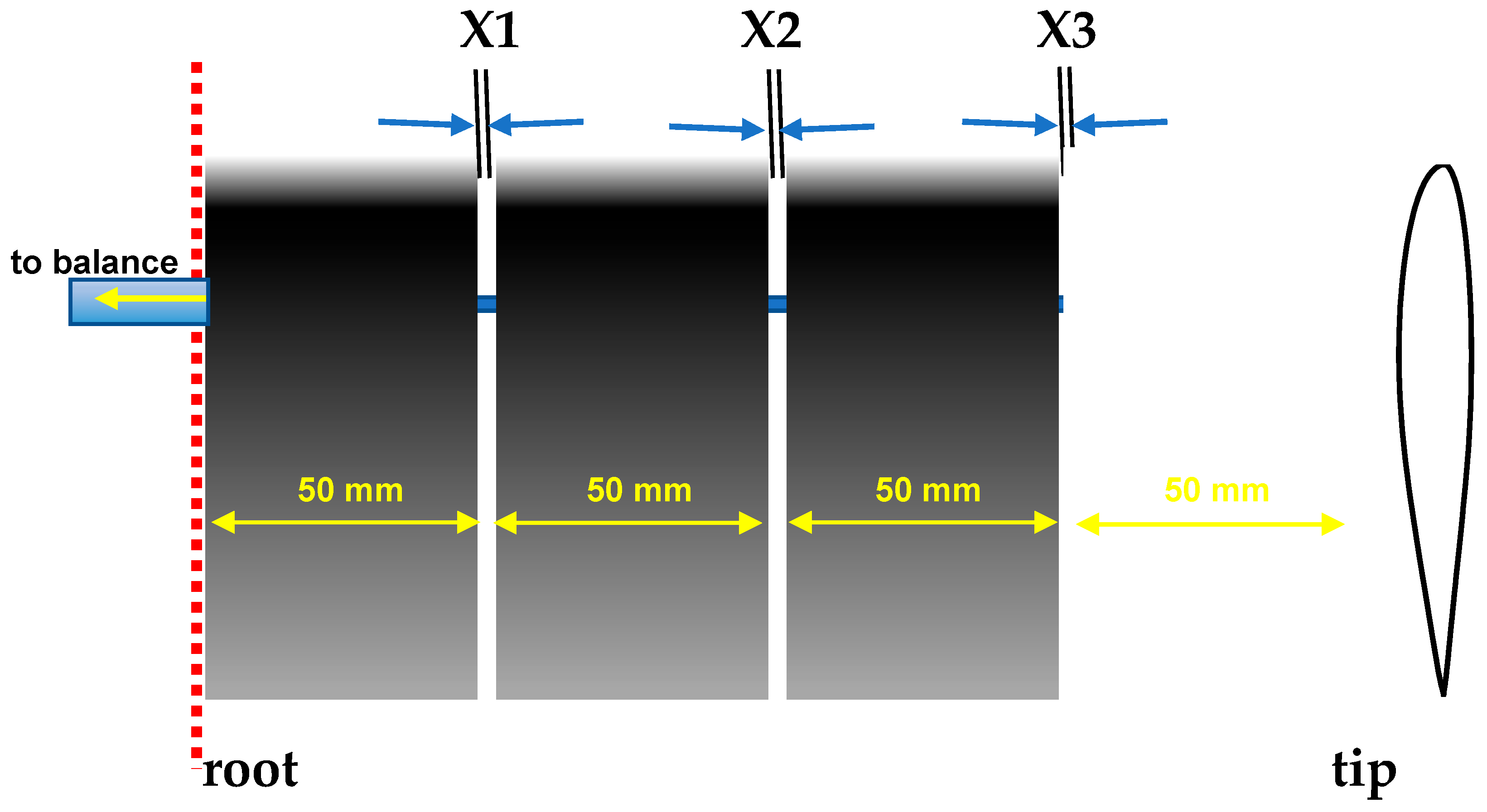
As an initial proof of concept, a wing was manufactured consisting of four separate panels (or elements), each with a nominal span of 50 mm, as shown in Figure 1. Four panels were selected as this selection yields elements with a geometric AR = ½. A range of panel gap values were used to expose the potential benefit of the configuration as well as the gap value at which the benefit started to decline. The panels were joined through a spanwise all-thread rod that secured and tightened the segments. Miniature spacers were used to position the panels such that gaps of X1 = X2 = X3 = 1 mm, 2 mm, and 4 mm (2Xi/b = 0.005, 0.01, and 0.02, respectively) were tested. The wing’s section was S8036. The S8036 is a thick profile (16%) with moderate camber (1.3%). This airfoil was chosen because its performance deteriorates quite severely for Re < 80,000 [11] due to open separation; thus, it represents a challenging test case. A reflection plane configuration was used for testing. The gap between the wing and the tunnel side wall was 0.35 mm (measured using a Feeler gauge). The wing was unswept with a taper ratio of one and an effective AR = 4 (based on a nominal root chord of 100 mm and a semi-span of 200 mm). The wing elements were rapid prototyped in ABS (acrylonitrile butadiene styrene). After manufacture, the wing elements were smoothed using 600 and 1200 grit sandpapers, following which they were painted using gloss black epoxy spray paint. Tests were undertaken at Re of 40,000, 60,000, and 80,000 (7.5 m/s, 11.2 m/s, and 15 m/s, respectively). Testing encompassed angle of attack sweeps for various Xi settings.
In addition to the tests described, additional lift response characterization was undertaken within the framework of a design of experiments test plan. A two-factor full factorial design was implemented to assess the sensitivity of the main Xi components as well as interactions between high and low settings at each Xi location.
Surface flow visualization was performed to elucidate the impact of the gaps between the wing panels from a physical perspective. Implementation involved setting the wing at a desired angle of attack, coating it with the visualization medium, and then quickly raising the wind tunnel to the desired velocity. Both still images and video were recorded for analysis. The visualization paint consisted of titanium dioxide suspended in kerosene, linseed oil, and oleic acid.
3. Results
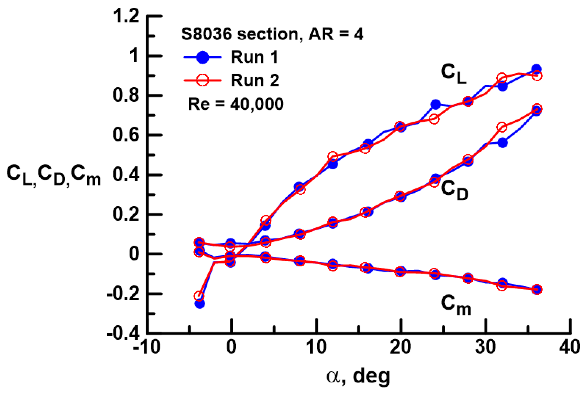
Repeatability of wind tunnel data is always a concern, but is especially so at low Re, where forces and moments are very small, and flows are often unsteady. Consequently, some cases were tested multiple times to assess repeatability. Of the configurations, the fused wing (X1 = X2 = X3 = 0) at Re = 40,000 represents the most challenging case as loads are the lowest. Repeated runs for this case are presented in Figure 2. As may be seen, repeatability for CL, CD, and Cm is very good.
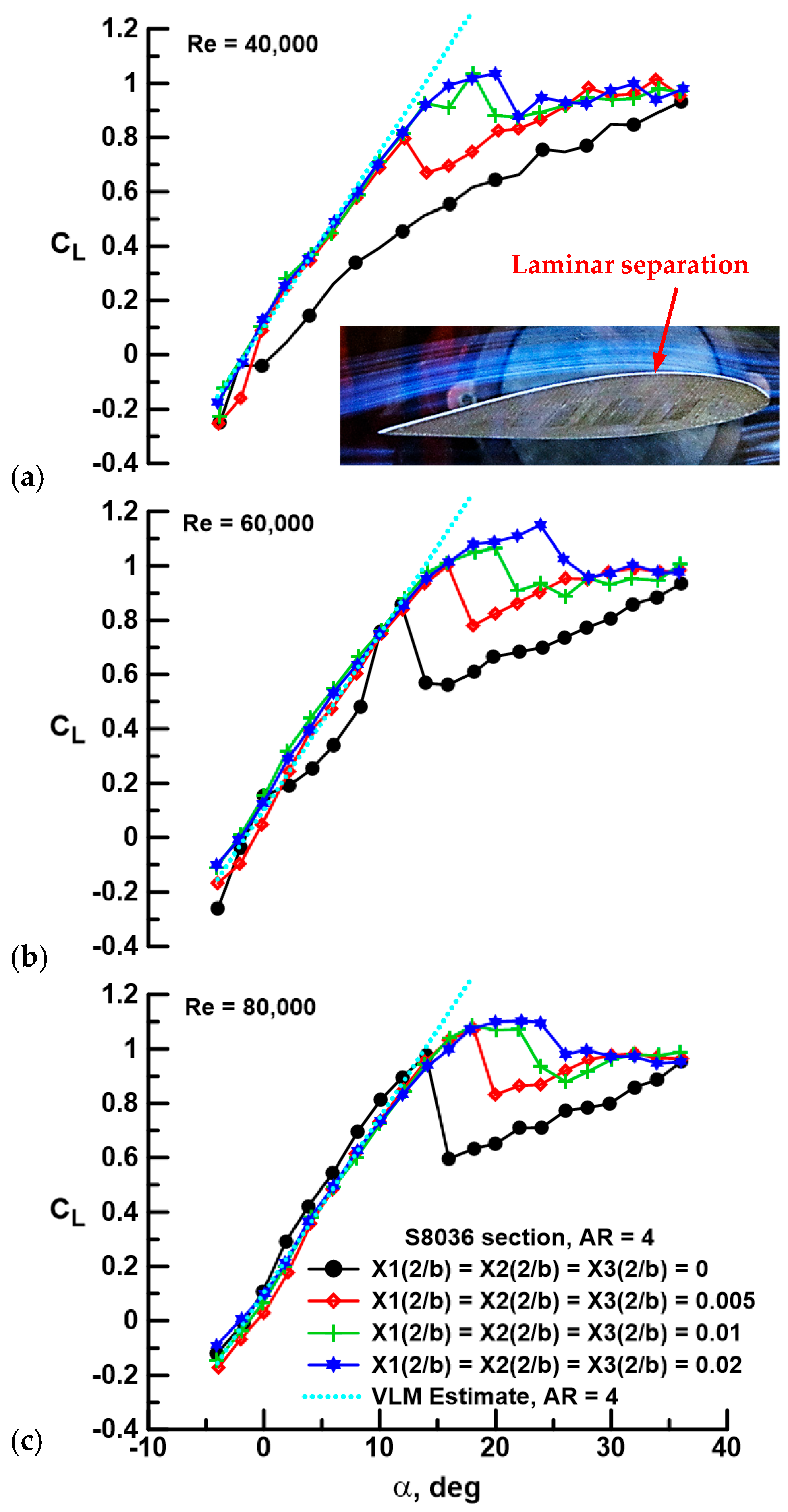
Figure 3 presents the effect of equidistant gap on the lift coefficient as affected by Re. The lift curve for the fused wing at Re = 40,000, shown in Figure 3a (black circles), indicates laminar separation without transition. Lift is low, and a clear stall is absent. The inset photograph in Figure 3a shows streamline rendering through a smoke wire; laminar separation is evident and supports the interpretation of the force balance data. Implementing a wing gap is observed to dramatically augment lift, yielding a linear lift curve with a distinct stall, reflective of the presence of a LSB, as will be described later. Included in Figure 3 is a vortex lattice estimate (VLM) using an in-house code for an AR = 4 wing of fused geometry (no gaps). A total of 800 panels were used (20 chordwise and 40 spanwise). As may be seen, the lift curve slope shows close accord with all segmented wing cases. Increasing gap shows a corresponding increase in the stall angle and maximum lift coefficient. A similar behavior is noted at Re = 60,000 and 80,000 (see Figure 3b,c). An increase in Re to 60,000, depicted in Figure 3b, shows improvement (i.e., delay) for all segmented cases in terms of αstall. Data for the fused wing are notable. The lift curve is indicative of open laminar separation; however, at α = 8 and 10 deg, data for the fused wing “jumps” up and coalesces with the segmented cases, indicative of transition and LSB formation. However, the flow subsequently detaches and resumes its former state. The formation of a LSB is indicated for Re = 80,000 for the fused wing; the lift curve is markedly improved, and a distinct stall is evident. It is notable that, despite the gaps between wing panels, lift for the segmented configurations is only moderately attenuated compared to the fused wing at Re = 80,000. In all cases, segmentation of the wing significantly delays stall and increases CLmax compared to the fused wing.
The effect of Re for a specific gap is examined in Figure 4. For the fused wing (see Figure 4a), the effect of Re is pronounced. Increasing Re transforms the flow from an open laminar separation state (Re = 40,000) to an intermediate state presenting a mix of open laminar separation and LSB formation depending on α (Re = 60,000) to a fully transitioned state where a LSB is present pre-stall (Re = 80,000). Notably, post-stall, all three curves coalesce as massively separated flow has a significantly reduced sensitivity to Re. For the segmented cases (Figure 4b–d), Re has little effect on the lift curve pre-stall. However, Re does affect stall characteristics, generally delaying αstall and increasing CLmax, although this behavior weakens as the gap increases. The overarching result from Figure 3 and Figure 4 is that spanwise wing segmentation is highly effective at augmenting wing lifting capability, showing little sensitivity to Re, and delaying stall onset markedly.
Figure 5 and Figure 6 present the effect of gap on the drag polar as affected by gap magnitude (Figure 5) and Re (Figure 6). At Re = 40,000 (see Figure 5a), laminar separation over the fused wing is reflected in a lift-dependent drag magnitude that is commensurate with that of a thin sharp-edged flat plate, for which the drag due to lift is given by CLtan(α). This expression is plotted and is seen to closely match those of the fused (gap = 0) cases in Figure 5a,b. Gap is seen to drastically reduce the drag due to lift component compared to the fused geometry for all cases. Included for reference in Figure 5 is the drag due to lift for a wing with elliptic spanwise loading and negligible sectional pressure drag [i.e., CDmin + CL2/(πAR)]. For a given Re as seen in Figure 5, increasing gap beyond the initial opening (i.e., Xi(2/b) = 0.005) causes a systematic rise in drag due to lift, although the onset of stall is delayed significantly. The minimum drag coefficient is not observed to increase notably with gap.
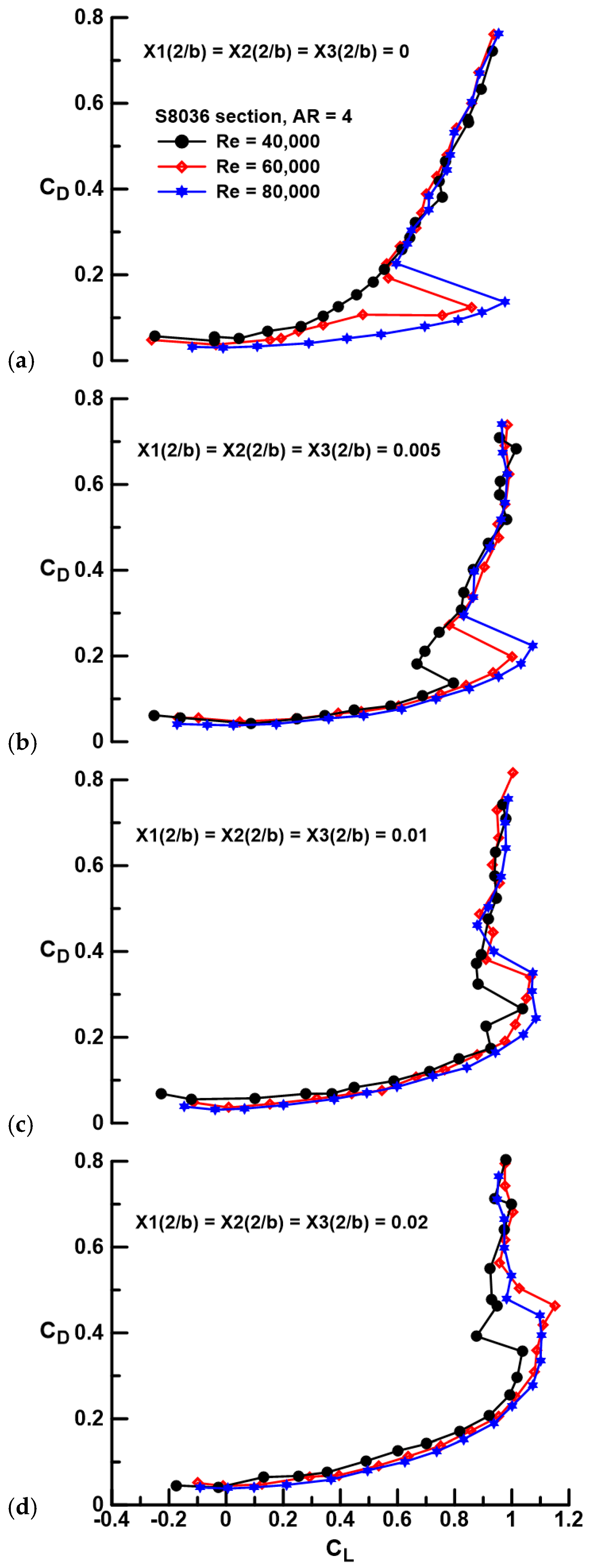
At an Re = 80,000, see Figure 5c, LSB formation yields superior drag performance for the fused wing compared to the gapped geometries, especially at higher lift coefficients. The explicit effect of Re for a given gap is most notable for the fused wing element, where significant Re effects are seen, see Figure 6a. LSB formation and thus flow re-attachment through this feature cause a notable reduction in drag due to lift compared to the laminar separation case (compare Re = 40,000 and 80,000). For the cases with gap, see Figure 6b–d, the effect of Re is weak on drag due to lift and appears to affect CDmin primarily, as may be expected. The net observation from Figure 5 and Figure 6 is that segmentation of the wing does not cause a significant drag penalty; in fact, the opposite is noted for Re < 80,000, i.e., drag is greatly attenuated compared to cases where the fused wing experiences laminar separation without transition. For a given Xi(2/b) value (i.e., 0.005, 0.01, and 0.02), Reynolds number does not appear to affect the drag-reducing efficacy of the spanwise gap.
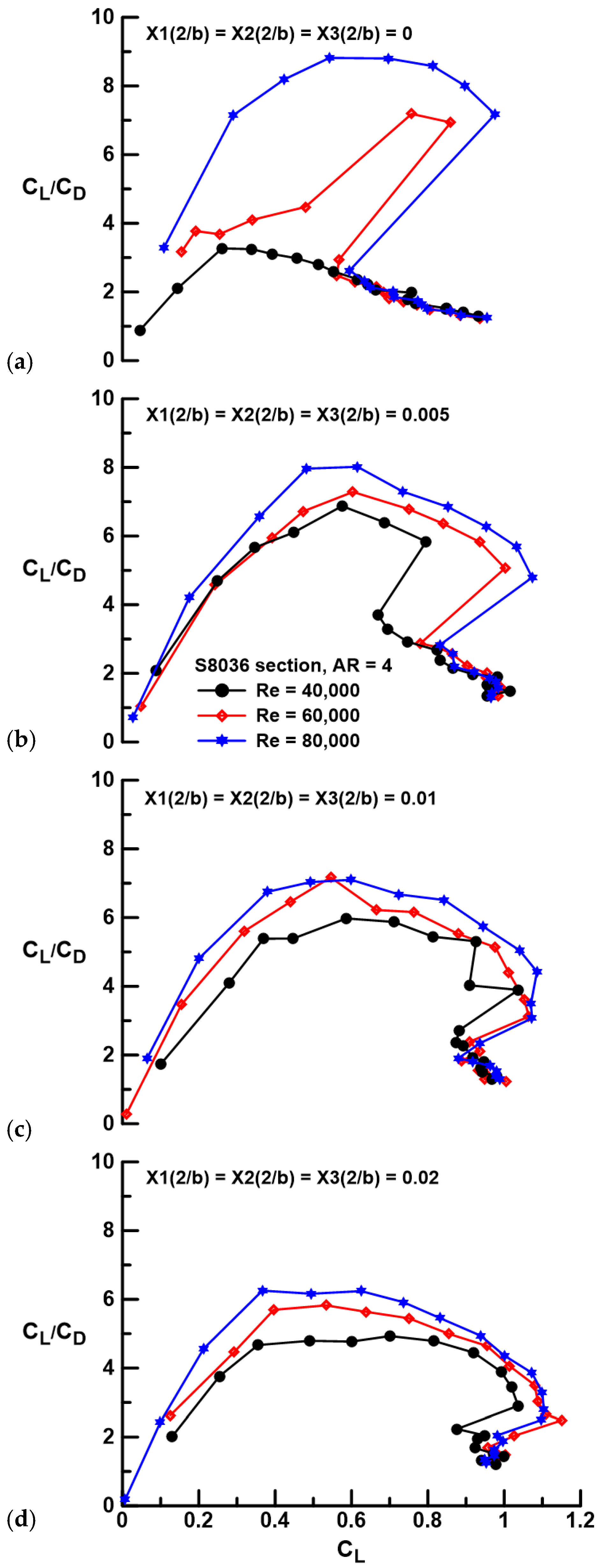
Examination of the lift and drag data indicates that gap can yield significant performance improvement; however, such gains are most meaningfully assessed through the examination of the range or efficiency metric; the lift-to-drag ratio is presented in Figure 7 and Figure 8. At Re = 40,000, separation severely attenuates the CL/CD ratio of the fused wing. Spanwise gap greatly augments efficiency, with a 111% increase in the peak lift-to-drag ratio between the Xi(2/b) = 0.005 (1 mm gap) case and the fused wing. The systematic drag rise associated with an increase in the gap between wing panels (see Figure 5) is observed to reduce efficiency with each subsequent gap increment. This behavior is seen to be consistent for the tested Re range, see Figure 7a–c. Once a LSB reliably forms on the fused wing (Re = 80,000, see Figure 7c), its performance surpasses that of any of the segmented configurations, showing a 10% increase in peak CL/CD over the Xi(2/b) = 0.005 configuration. Reynolds number has a profound impact on the efficiency of the wings, both fused and with gaps, see Figure 8. In all instances, whether the wing is fused or has gaps, increasing Re improves the lift-to-drag ratio. This behavior is primarily driven by the reduction in CDmin with increasing Re. For the fused wing, as shown in Figure 8a, the formation of a LSB that supplants open laminar separation with increasing Re causes a marked improvement in wing efficiency.
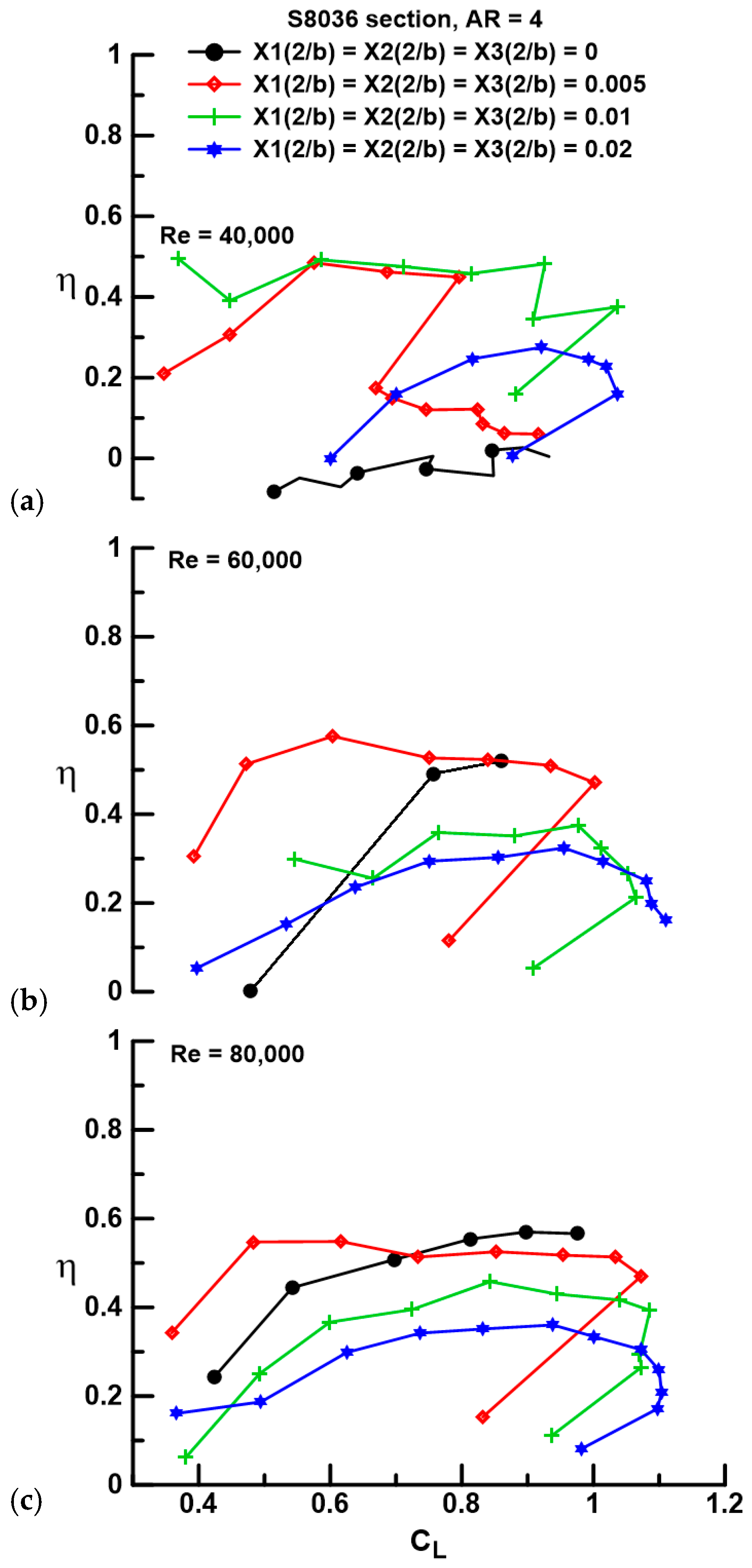
The attainable leading-edge suction is a parameter that indicates the extent of axial force development compared to the theoretical maximum when the wing experiences elliptic spanwise loading. The parameter, η, is given by:
and shows the ratio of the axial force component to that assuming elliptic spanwise loading coupled with negligible sectional pressure drag. The fused wing at Re = 40,000, see Figure 9a, shows essentially zero leading-edge suction, a result consistent with that seen in Figure 5a and indicates that the net-resultant-pressure-induced loading acts normal to the wing chord, i.e., the wing behaves essentially as a sharp-edged flat plate. Flow improvement caused by spanwise gap is seen to raise the suction levels to approximately 40% to 50% of the maximum value (i.e., η = 1). A larger gap is noted to attenuate the suction level.
A summary of performance metrics as a function of panel gap is presented in Figure 10. At Re = 40,000, gap significantly augments the peak CL/CD ratio compared to the fused wing, although any gap increase beyond the initial opening (Xi(2/b) = 0.005) diminishes efficiency. Increasing Re to 60,000 yields a net increase in the lift-to-drag ratio for all gaps with a plateau in magnitude for Xi(2/b) ≤ 0.01. Boundary layer improvement for the fused wing at Re = 80,000 results in the highest (CL/CD)max, with initial and increasing gap causing a fairly linear decrease in wing efficiency. The maximum lift coefficient improves with gap and to a lesser extent Re in all cases. Note that a value for CLmax is not included for the fused wing at Re = 40,000 as the wing did not stall in the classical sense. The onset of stall is delayed by gap as well as Re. Even at Re = 80,000, the largest gap (Xi(2/b) = 0.02) shows a 57% increase in the stall angle compared to the fused wing. The overarching result is that gap significantly improves wing efficiency compared to a fused wing in the absence of LSB formation. A fused wing outperforms a segmented wing from an efficiency perspective when transition is caused by a LSB. In terms of stall delay and maximum lift coefficient, wing segmentation yields superior performance compared to the fused wing for all tested Re. Note that this result applies to the tested cases (i.e., wing geometry, the number of panels, and gap sizes); its generality is uncertain.
The effect of gap on the quarter chord pitching moment is examined in Figure 11. Laminar separation is seen to increase the magnitude of the nose down pitching moment, see Figure 11a, and reflects the lack of pressure recovery over the aft suction surface of the wing. Prior to the onset of stall, the largest evaluated gap, Xi(2/b) = 0.02, shows an increased negative slope compared to the smaller gaps, suggesting an aft movement of the aerodynamic center (see Figure 11a,b). For Re = 80,000, all data sets appear to coalesce pre-stall. The implementation of gap does not appear to introduce any deleterious behaviors that may affect stability.
As a whole, the force balance data suggest that a gap is beneficial at Re ≤ 60,000 for the current geometry and airfoil section. Benefit for Re > 60,000 is related to a stall onset delay. In practice, implementation would be most advantageous if the gap was adjustable. For a small-scale UAV, the implementation of a variable gap could easily be achieved using a screw thread or linear servo-based actuator.
For proof of concept, a multi-panel reflection plane wing was designed and manufactured. Optimality of the design was not pursued as the study was exploratory in nature. However, it is of value to ascertain the impact of the parameter (Xi) settings on performance. Consequently, a design of experiments approach was implemented to see if any gap locations were more “impactful” and if different locations interacted with each other. The wing geometry has three parameters (or factors) (X1, X2, and X3) and four levels (i.e., gaps of 0, 0.005, 0.01, and 0.02). Using a full factorial design, this would require 43 = 64 runs. However, the purpose of this analysis is to ascertain sensitivity to the presence of the gap, not to the gaps’ magnitude. Thus, the levels were set as either closed (Xi(2/b) = 0) or fully open (Xi(2/b) = 0.02). This reduces the number of tests to 23 = 8. The results would allow the determination of the main effects (the impact of the factor on itself when its level is high or low) as well as interaction effects (i.e., when the influence of one factor depends on the level of another factor, e.g., does X1 cause greater lift modulation if X2(2/b) is 0 or 0.02, etc.). A response surface for the tests (and the lift coefficient as shown) would be of the form given by Equation (2) and is simply a surface curve fit accounting for all possible variable interactions.

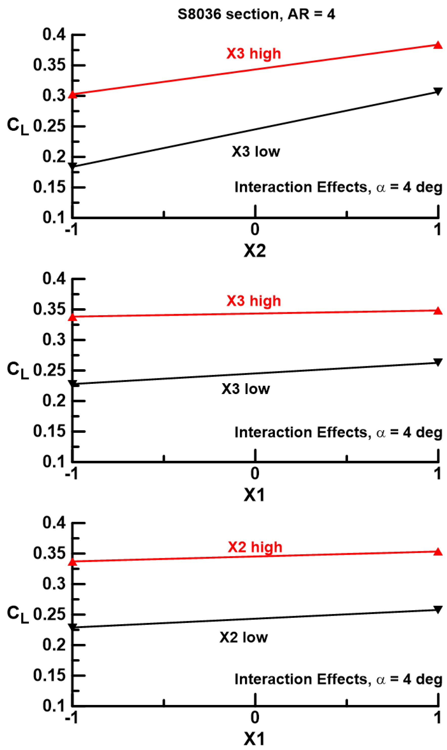
Thus, there are three main effects and four interactions. A response surface was established for α = 4 deg at Re = 40,000 with coefficients as determined in Table 1 using a multiple linear regression analysis. Main and interaction effects are also shown graphically in Figure 12. The data were processed in coded form, i.e., the low-gap setting (0 mm) was designated as −1 and the largest gap setting (4 mm) was defined as +1. Coded data allow the direct comparison of effects.
Main effects for the three gap locations indicate an increase in CL with gap, as already indicated. However, the effectiveness of each location is not equal; the innermost location X1 yields far less lift augmentation (a smaller slope) than the two outer locations, X2 and X3. A gap at X2 or X3 appears somewhat equivalent in its ability to increase lift. This result is also indicated in the magnitude of the coefficients A1, A2, and A3 as presented in Table 1. Interaction effects as shown in Figure 12 are marginal (inferred through the moderate slopes of the plots, which are also reflected in the coefficient magnitudes in Table 1 for A4 to A7). Only gap locations X2 and X3 appear to have a moderate interaction. Interaction effects may also be examined with reference to Figure 13. In this plot, the response of a factor at both high- and low-level settings is indicated when a second factor is set to a high and a low level. Consequently, if setting the X1 gap (as an example) yields the same lift increment whether the gap at location X2 is open or closed, it indicates no interaction has occurred. Thus, the lines for this case would be parallel. As surmised from Figure 13, gap locations X1 and X3 show very little interaction, while for X2 and X3, the lines are not quite parallel, indicating a moderate interaction. The data suggest that the lift increment caused by the X2 gap is attenuated slightly if gap X3 is open. Note that the main and interaction effects would likely vary for other wing geometries that have a different number of wing panels, different spacing locations, etc.
Force balance data indicate that spanwise wing segmentation is effective at improving performance at low Re, but it does not give insight into the physics associated with the improvements. Consequently, surface flow visualization was undertaken. Figure 14a shows surface skin friction patterns over the fused wing and the Xi(2/b) = 0.005 gap geometry at α = 4 deg and Re = 40,000. The difference in the flow fields is striking; the fused wing shows massive laminar separation with recirculation (evident in video), while the segmented wing shows clear imprints of LSBs. Intuitively, the gaps between the segments would force the loading to zero, or at least significantly attenuate it. As noted in [31], the proximity to the wing tip tends to terminate the LSB and shift it aft as the wing’s effective α is reduced. Although there does appear to be a termination of the bubble near the wing tip, the inner two panels show weak evidence of such behavior. Increasing Re to 80,000, see Figure 14b, shows clear LSB formation over the fused wing coincident with the drastic improvement in performance as seen in Figure 4, Figure 5, Figure 6 and Figure 7. The location and chordwise extent of the LSB is similar for both the fused and the segmented wing (suggesting similar chordwise load distributions); this behavior is maintained at α = 8 deg, Figure 14c. Compared to Re = 40,000, the LSBs over the segmented wings are seen to terminate slightly before the gap, predominantly on the outboard end of each wing panel. At low Re, segmentation of the wing offers an efficient mechanism of flow control that promotes the transition of the separated shear layer, causing flow re-attachment. Low aspect ratio wings have a well-documented high angle of attack capability, stemming from the stabilizing downwash from the wing tip vortex, as well as a reduction in the effective angle of attack due to the downwash field [32].
4. Conclusions
In this article, a low-speed wind tunnel investigation is documented that explores a novel form of flow control applicable to wing operation at low Re (≤60,000). An S8036-profiled wing with an effective aspect ratio of four was segmented into four spanwise panels, with the gap between the panels being variable. Force balance data and surface flow topology are presented for Re spanning 40,000 to 80,000. The results show that at Re = 40,000, a small gap between the panels, equal to 0.5% of the semi-span, can significantly augment lift as well as attenuate drag through the formation of a laminar separation bubble on each panel that serves as the flow’s re-attachment mechanism. An increase in the peak lift-to-drag ratio of up to 83% compared to the fused was measured at Re = 40,000. Increasing the gap between the panels beyond 0.5% improves lift behavior but does cause a drag penalty. For the tested Re range, gaps are noted to be highly effective stall control devices, increasing the maximum lift coefficient and stall angle. At Re = 80,000, the performance of the fused wing (no gaps) improves markedly due to the natural formation of a laminar separation bubble. In this instance, gaps are not beneficial pre-stall but still delay the stall angle to a larger angle of attack, with an observed delay of approximately 10 deg, while concomitantly increasing the maximum lift coefficient by 13%. The effects of airfoil profile and wing AR on the efficacy of spanwise segmentation require further investigation.
Funding
This research received no external funding.
Data Availability Statement
The data used within this article are available from the author upon reasonable request.
Conflicts of Interest
The author declares no conflicts of interest.
Abbreviations
The following abbreviations are used in this manuscript.
| Ai | coefficient |
| b | wingspan |
| c | chord |
| C | constant |
| CD | drag coefficient, D/(qS) |
| CL | lift coefficient, L/(qS) |
| CLmax | maximum lift coefficient |
| Cm | pitching moment coefficient, PM/(qSc) |
| D | drag |
| L | lift |
| PM | pitching moment |
| q | dynamic pressure |
| S | reference area |
| i | index |
| Xi | gap position and magnitude |
| η | leading-edge suction parameter |
| 1, 2, 3 | gap number |
References
- Laitone, E.V. Wind Tunnel Tests of Wings at Reynolds Numbers Below 70000. Expts Fluids 1997, 23, 405–409. [Google Scholar] [CrossRef]
- Liu, T.; Kuykendoll, K.; Rhew, R.; Jones, S. Avian Wings. In Proceedings of the 24th AIAA Aerodynamic Measurement Technology and Ground Testing Conference, Portland, OR, USA, 28 June–1 July 2004. AIAA Conference Paper 2004-2186. [Google Scholar]
- Pennycuick, C.J.A. Wind-Tunnel Study of Gliding Flight in the Pigeon Columba Livia. J. Expt. Biol. 1968, 49, 509–526. [Google Scholar] [CrossRef]
- Withers, P.C. An Aerodynamic Analysis of Bird Wings as Fixed Aerofoils. J. Expt. Biol. 1981, 90, 143–162. [Google Scholar] [CrossRef]
- Oehme, H.; Kitzler, U. On the Geometry of the Avian Wing (Studies on the Biophysics and Physiology of Avian Flight 11); NASA-TT-F-16901; NASA: Washington, DC, USA, 1975. [Google Scholar]
- Okamoto, M.; Yasuda, K.; Azuma, A. Aerodynamic Characteristics of the Wings and Body of a Dragonfly. J. Expt. Biol. 1996, 199, 281–294. [Google Scholar] [CrossRef] [PubMed]
- Lissaman, P.B.S. Low-Reynolds-Number Airfoils. Annu. Rev. Fluid Mech. 1983, 15, 223–239. [Google Scholar] [CrossRef]
- Fisher, A.M. The Effect of Freestream Turbulence on Fixed and Flapping Micro Air Vehicle Wings. Ph.D. Dissertation, RMIT University, Melbourne, Australia, 2013. [Google Scholar]
- Traub, L.W.; Cooper, E. Experimental Investigation of Pressure Measurement and Airfoil Characteristics at Low Reynolds Numbers. J. Aircr. 2009, 45, 1322–1333. [Google Scholar] [CrossRef]
- Mueller, T.J. The Influence of Laminar Separation and Transition on Low Reynolds Number Airfoil Hysteresis. J. Aircr. 1985, 22, 763–770. [Google Scholar] [CrossRef]
- Traub, L.W.; Coffman, C. Efficient Low Reynolds Number Airfoils. J. Aircr. 2019, 56, 1987–2003. [Google Scholar] [CrossRef]
- Horton, H. Laminar Separation Bubbles in Two and Three Dimensional Incompressible Flows. Ph.D. Thesis, Queen Mary University of London, London, UK, 1968. [Google Scholar]
- Gaster, M. The Structure and Behaviour of Laminar Separation Bubbles; Reports and Memoranda No. 3595; Ministry of Technology: London, UK, 1969. [Google Scholar]
- Swift, K.M. An Experimental Analysis of the Laminar Separation Bubble at Low Reynolds Numbers. Master’s Thesis, University of Tennessee, Knoxville, TN, USA, 2009. [Google Scholar]
- Watmuff, J.H. Evolution of a wave packet into vortex loops in a laminar separation bubble. J. Fluid Mech. 1999, 397, 119–169. [Google Scholar] [CrossRef]
- Pauley, L.L.; Moin, P.; Reynolds, W.C. The structure of two-dimensional separation. J. Fluid Mech. 1990, 220, 397–411. [Google Scholar] [CrossRef]
- Abdalla, I.E.; Yang, Z. Numerical study of the instability mechanism in transitional separating-reattaching flow. Int. J. Heat Fluid Flow 2004, 25, 593–605. [Google Scholar] [CrossRef]
- Toppings, C.E.; Yarusevych, S. Structure and Dynamics of a Laminar Separation Bubble Near A Wingtip. J. Fluid Mech. 2021, 929, A39. [Google Scholar] [CrossRef]
- Traub, L.W. Experimental Investigation of the Effect of Trip Strips at low Reynolds Number. J. Aircr. 2011, 48, 1776–1784. [Google Scholar] [CrossRef]
- Jones, G.; Santer, M.; Debiasi, M. Control of Flow Separation Around an Airfoil at Low Reynolds Numbers using Periodic Surface Morphing. J. Fluids Struct. 2018, 76, 536–557. [Google Scholar] [CrossRef]
- DeMauro, E.P.; Dellorso, H.; Zaremski, S.; Leong, C.M.; Amitay, M. Control of Laminar Separation Bubble On NACA 0009 Airfoil Using Electroactive Polymers. AIAA J. 2015, 53, 2270–2279. [Google Scholar] [CrossRef]
- Jones, G.; Santer, M.; Papadakis, G. Control of low Reynolds number flow around an airfoil using periodic surface morphing: A numerical study. J. Fluids Struct. 2018, 76, 95–115. [Google Scholar] [CrossRef]
- Sato, M.; Nonomura, T.; Okada, K.; Asada, K.; Aono, H.; Yakeno, A.; Abe, Y.; Fujii, K. Mechanisms For Laminar Separated-Flow Control Using Dielectric-Barrier-Discharge Plasma Actuator At Low Reynolds Number. Phys. Fluids 2015, 27, 117101. [Google Scholar] [CrossRef]
- Zhang, W.; Zhang, Z.; Chen, Z.; Tang, Q. Main Characteristics of Suction Control of Flow Separation of an Airfoil at Low Reynolds Numbers. Eur. J. Mech. 2017, 65, 88–97. [Google Scholar] [CrossRef]
- Ogawa, T.; Asada, K.; Sato, M.; Tatsukawa, T.; Fujii, K. Computational Study of the Plasma Actuator Flow Control for an Airfoil at Pre-Stall Angles of Attack. Appl. Sci. 2022, 12, 9073. [Google Scholar] [CrossRef]
- Wang, L.; Wong, C.W.; Alam, M.M.; Zhou, Y. Post-Stall Flow Control Using A Sawtooth Plasma Actuator In Burst Mode. Aerosp. Sci. Technol. 2020, 107, 106251. [Google Scholar] [CrossRef]
- Feero, M.A.; Lavoie, P.; Sullivan, P.E. Influence of Synthetic Jet Location on Active Control of an Airfoil at Low Reynolds Number. Exp. Fluids 2017, 58, 99. [Google Scholar] [CrossRef]
- Ogawa, T.; Asada, K.; Sekimoto, S.; Tatsukawa, T.; Fujii, K. Dynamic Burst Actuation to Enhance the Flow Control Authority of Plasma Actuators. Aerospace 2021, 8, 396. [Google Scholar] [CrossRef]
- Greenblatt, D.; Goksel, B.; Schule, C.Y.; Romann, D.; Paschereit, C.O. Dielectric Barrier Discharge Flow Control at Very Low Flight Reynolds Numbers. AIAA J. 2008, 46, 1528–1541. [Google Scholar] [CrossRef]
- Kline, S.J.; McClintock, F.A. Describing Uncertainties in Single-Sample Experiments. Mech. Eng. 1953, 75, 3–9. [Google Scholar]
- Bastedo, W.G.; Mueller, T.J. The Spanwise Variation of Laminar Separation Bubbles on Finite Wings at Low Reynolds Number. In Proceedings of the 18th Fluid Dynamics and Plasmadynamics and Lasers Conference, Cincinnati, OH, USA, 16–18 July 1985. AIAA Conference Paper 85-1590. [Google Scholar]
- Traub, L.W. Examination and Prediction of the Lift Components of Low Aspect Ratio Rectangular Flat Plate Wings. Aerospace 2023, 10, 597. [Google Scholar] [CrossRef]
Figure 1.
Segmented wing geometry and nomenclature, freestream direction is top to bottom.

Figure 2.
Data repeatability for X1 = X2 = X3 = 0 (fused wing) at Re = 40,000.

Figure 3.
Effect of gap and Re on CL for a Re of (a) 40,000, (b) 60,000, and (c) 80,000. Inset image shows smoke-rendered streamline behavior over the fused wing at α = 4 deg and Re = 40,000.
Figure 3.
Effect of gap and Re on CL for a Re of (a) 40,000, (b) 60,000, and (c) 80,000. Inset image shows smoke-rendered streamline behavior over the fused wing at α = 4 deg and Re = 40,000.

Figure 4.
Effect of Re and gap on CL for equidistant gaps Xi(2/b) of (a) 0, (b) 0.005, (c) 0.01, and (d) 0.02.
Figure 4.
Effect of Re and gap on CL for equidistant gaps Xi(2/b) of (a) 0, (b) 0.005, (c) 0.01, and (d) 0.02.

Figure 5.
Effect of gap and Re on CD for a Re of (a) 40,000, (b) 60,000, and (c) 80,000.

Figure 6.
Effect of Re and gap on CD for equidistant gaps Xi(2/b) of (a) 0, (b) 0.005, (c) 0.01, and (d) 0.02.
Figure 6.
Effect of Re and gap on CD for equidistant gaps Xi(2/b) of (a) 0, (b) 0.005, (c) 0.01, and (d) 0.02.

Figure 7.
Effect of gap and Re on the lift-to-drag ratio for a Re of (a) 40,000, (b) 60,000, and (c) 80,000.
Figure 7.
Effect of gap and Re on the lift-to-drag ratio for a Re of (a) 40,000, (b) 60,000, and (c) 80,000.

Figure 8.
Effect of Re and gap on the lift-to-drag ratio for equidistant gaps Xi(2/b) of (a) 0, (b) 0.005, (c) 0.01, and (d) 0.02.
Figure 8.
Effect of Re and gap on the lift-to-drag ratio for equidistant gaps Xi(2/b) of (a) 0, (b) 0.005, (c) 0.01, and (d) 0.02.

Figure 9.
Effect of gap and Re on the attainable leading-edge suction for a Re of (a) 40,000, (b) 60,000, and (c) 80,000.
Figure 9.
Effect of gap and Re on the attainable leading-edge suction for a Re of (a) 40,000, (b) 60,000, and (c) 80,000.

Figure 10.
Effect of gap and Re on performance metrics; (a) (CL/CD)max, (b) CLmax, and (c) αstall.

Figure 11.
Effect of gap and Re on Cm for a Re of (a) 40,000, (b) 60,000, and (c) 80,000.

Figure 12.
Effect of gap location on main and interaction effects for α = 4 deg at Re = 40,000.

Figure 13.
Gap location interaction effects for α = 4 deg at Re = 40,000.

Figure 14.
Surface flow visualization over the fused and segmented wing for (a) an α of 4 deg and Re of 40,000, (b) an α of 4 deg and Re of 80,000, and (c) an α of 8 deg and Re of 80,000.
Figure 14.
Surface flow visualization over the fused and segmented wing for (a) an α of 4 deg and Re of 40,000, (b) an α of 4 deg and Re of 80,000, and (c) an α of 8 deg and Re of 80,000.


Table 1.
Response surface coefficients for α = 4 deg at Re = 40,000.
| Coefficient | Variable(s) | Coefficient Value |
|---|---|---|
| A1 | X1 | 0.01122 |
| A2 | X2 | 0.05100 |
| A3 | X3 | 0.04908 |
| A4 | X1 X2 | −0.00315 |
| A5 | X1 X3 | −0.00619 |
| A6 | X2 X3 | −0.01042 |
| A7 | X1 X2 X3 | −0.00363 |
| C | - | 0.29429 |
Disclaimer/Publisher’s Note: The statements, opinions and data contained in all publications are solely those of the individual author(s) and contributor(s) and not of MDPI and/or the editor(s). MDPI and/or the editor(s) disclaim responsibility for any injury to people or property resulting from any ideas, methods, instructions or products referred to in the content. |
© 2024 by the author. Licensee MDPI, Basel, Switzerland. This article is an open access article distributed under the terms and conditions of the Creative Commons Attribution (CC BY) license (https://creativecommons.org/licenses/by/4.0/).
Share and Cite
MDPI and ACS Style
Traub, L.W. Wing Efficiency Enhancement at Low Reynolds Number. Aerospace 2024, 11, 320. https://0-doi-org.brum.beds.ac.uk/10.3390/aerospace11040320
AMA Style
Traub LW. Wing Efficiency Enhancement at Low Reynolds Number. Aerospace. 2024; 11(4):320. https://0-doi-org.brum.beds.ac.uk/10.3390/aerospace11040320
Chicago/Turabian StyleTraub, Lance W. 2024. "Wing Efficiency Enhancement at Low Reynolds Number" Aerospace 11, no. 4: 320. https://0-doi-org.brum.beds.ac.uk/10.3390/aerospace11040320
Note that from the first issue of 2016, this journal uses article numbers instead of page numbers. See further details here.