
Nonlinear Modeling and Control Strategy Based on Type-II T-S Fuzzy in Bi-Directional DC-AC Converter


1
College of Electrical Engineering and Automation, Fuzhou University, Fuzhou 350108, China
2
Quanzhou Institute of Equipment Manufacturing, Haixi Institutes, Chinese Academy of Sciences, Quanzhou 362216, China
3
Contemporary Amperex Technology Co., Limited, Ningde 352100, China
*
Author to whom correspondence should be addressed.
Electronics 2024, 13(9), 1684; https://0-doi-org.brum.beds.ac.uk/10.3390/electronics13091684
Submission received: 18 March 2024
/
Revised: 19 April 2024
/
Accepted: 22 April 2024
/
Published: 26 April 2024
(This article belongs to the Special Issue Recent Advances in Electrified Vehicles and Transportation Electrification)
Abstract
:Bi-directional DC-AC converters are widely used in the field of electric vehicle-to-grid. However, the inductance of the grid-side interface filter is affected by the length of the grid connection and the power level, which presents nonlinear characteristics. This poses challenges for high-performance grid waveform control. In this paper, a modeling method for bi-directional DC-AC grid-connected converters based on type-II T-S fuzzy models is proposed, and the corresponding type-II T-S fuzzy control strategy is designed to address the parameter uncertainty and non-linearity issues. Simulation results show that type-II T-S fuzzy control offers superior control performance and better current waveform quality compared to type-I T-S fuzzy control under uncertainty parameter conditions. The effectiveness of the proposed strategy is further validated through a 1 kW prototype of a bi-directional DC-AC converter.
1. Introduction
Due to global efforts to reduce carbon emissions and improve energy efficiency, the development and application of electric vehicles (EVs) have been widely promoted [1]. However, with the popularity of EVs, they impose a significant load on the distribution network and affect the stability of the grid [2,3]. Vehicle-to-grid (V2G) technology, shown in Figure 1, is proposed to better alleviate this problem through intelligent energy management and control between the EV energy storage system and the grid in order to achieve a more stable two-way power flow [4]. But, the process of EVs-charging and V2G cannot be separated from the use of converters such as DC-AC and DC-DC [5]. Therefore, it becomes crucial to control the bi-directional DC-AC converter to enhance the stability of power flow in V2G technology. Conventional full-bridge DC-AC converters have switching dead time, which causes the distortion of the output waveform, reduces efficiency and increases losses. Common mode current is generated under unipolar modulation, which requires auxiliary circuits to eliminate leakage currents and increase the complexity of the circuit. Dual-buck half-bridge converters are characterized by high reliability, no dead time and no leakage current generation [5,6,7], which has ability to overcome the above drawbacks. Hence, it is proposed to apply in areas requiring high power reliability and efficiency, like EVs [8].
Currently, there are few studies related to the nonlinearities of inductors, and common models include the Preisach model and the J-A hysteresis model [9]. In order to reduce the harmonics due to inductance variations in the current [10,11], some papers [12,13] have proposed an improved control strategy based on a proportional resonance regulator and a combined proportional–integral control method based on linear and nonlinear controllers, which adjusts the gain of the proportional resonant regulator through the online adaptive estimation of the nonlinear filtered inductance, thus ensuring that the THD (total harmonic distortion) is less than 5%. Paper [14] proposed a single-sensor current balancing method with less complexity and a smaller volume by analyzing the total current after interleaving, and utilizing the nonlinear behavior of inductors in interleaved DC-DC converters. In [15], the characteristics of wire-wound power inductors were investigated. The static model was determined, the factors affecting the temperature and DC bias were investigated, the inductance current curves were fitted by polynomials and, finally, the inductance characteristics at different currents as well as the inductance characteristics at different temperatures were obtained. By adopting the Euler–Lagrange formalism, a nonlinear model for a buck–boost DC-DC power converter was proposed, which can regulate the output voltage effectively [16]. Paper [17] analyzed the instantaneous magnetization power calculated from the inductor hysteresis loop, divided the instantaneous magnetization power into oscillating and absorbing parts and calculated the R-L parameters of the nonlinear hysteresis inductor model. In addition, a nonlinear inductive power transfer system with magnetically saturated inductors was proposed in [18] to obtain a stable output voltage independent of coupling coefficients and load variations.
Dual-buck bi-directional converters require the use of more inductors than conventional full bridge inverters, and the nonlinearity of the inductors affects the efficient control of the converter. To solve these problems, paper [19] proposed a single inductor dual-buck topology where the inductor can be fully utilized. However, the conduction loss significantly increased, which affects the conversion efficiency. Considering the controller design of the dual-buck bi-directional converter, it usually employs dual-loop control to satisfy the voltage and current to meet the waveform as well as amplitude requirements [20]. Paper [21] combined an active power decoupling buffer with a dual-buck converter to develop a single-loop direct input current ripple mitigation control method, which simplifies the ripple limiting control structure, reduces the construction cost of the converter and improves the power density. With the development of high-frequency technology, it has advantages, especially in the use of chip-controlled power switches.
The type-II T-S fuzzy principle mainly includes stability analysis, optimal design of fuzzy membership and practical use of controller for specific objects in combination with other advanced control methods [22]. Utilizing the approaching ability of a type-II T-S fuzzy model, paper [23] proposed a controller for a type-II T-S fuzzy time-lag system with time-lag state feedback to solve the finite time stabilization problem of nonlinear interconnected system with time-varying time-lag. Based on the extreme value of the membership function type-I and type-II, paper [24] simplified the stability judgment condition for s T-S fuzzy system, which provides a graphical method for analyzing the stability condition of the membership degree. With the nonlinear transverse dynamics of the vehicle system, paper [25] proposed an adaptive event-triggered dynamic output-feedback type-II T-S fuzzy control method for autonomous electric vehicle systems to ensure the stochastic stability and performance of the vehicle system. Paper [26] focused on the robust control problem of T-S fuzzy discrete systems of type II with input delays and network attacks, utilizing the lower and upper membership functions of type-II T-S fuzzy discrete systems to capture parameter uncertainty. Therefore, compared with type-I, type-II T-S fuzzy control is not only better in terms of consideration of membership degree, but also provides better control in applications in nonlinear and high-uncertainty environments. However, there is a lack of research on the use of control and modelling of nonlinear circuits.
In this paper, the dual-buck bi-directional DA-AC converter is taken as the object of study, T-S fuzzy with universal approximation ability to nonlinearity is selected to model the inductor, and this model is used as the basis for the design of the T-S fuzzy controller in combination with the principle of parallel distribution compensation (PDC). A type-II T-S fuzzy single-cycle controller is designed, the stability of the system under the new controller is analyzed and finally the control of the system is improved by the addition of the voltage outer loop. Through simulation and comparison, the type-II T-S fuzzy controller outperforms the type-I T-S fuzzy controller under the condition of uncertainty in the system, and the system has a better robustness and meets the criteria of grid-connected distortion rate, which verifies the feasibility and effectiveness of the algorithm. Finally, according to the previous analysis of the working principle of the dual-buck bi-directional converter and the design of the controller, an experimental prototype platform based on the TMS320F28377D digital control with a rated power 1 kW is fabricated, and the feasibility of the algorithm is finally verified through experimental analysis.
2. Materials and Methods
2.1. Mathematical Modeling of Dual-Buck Bi-Directional Converter
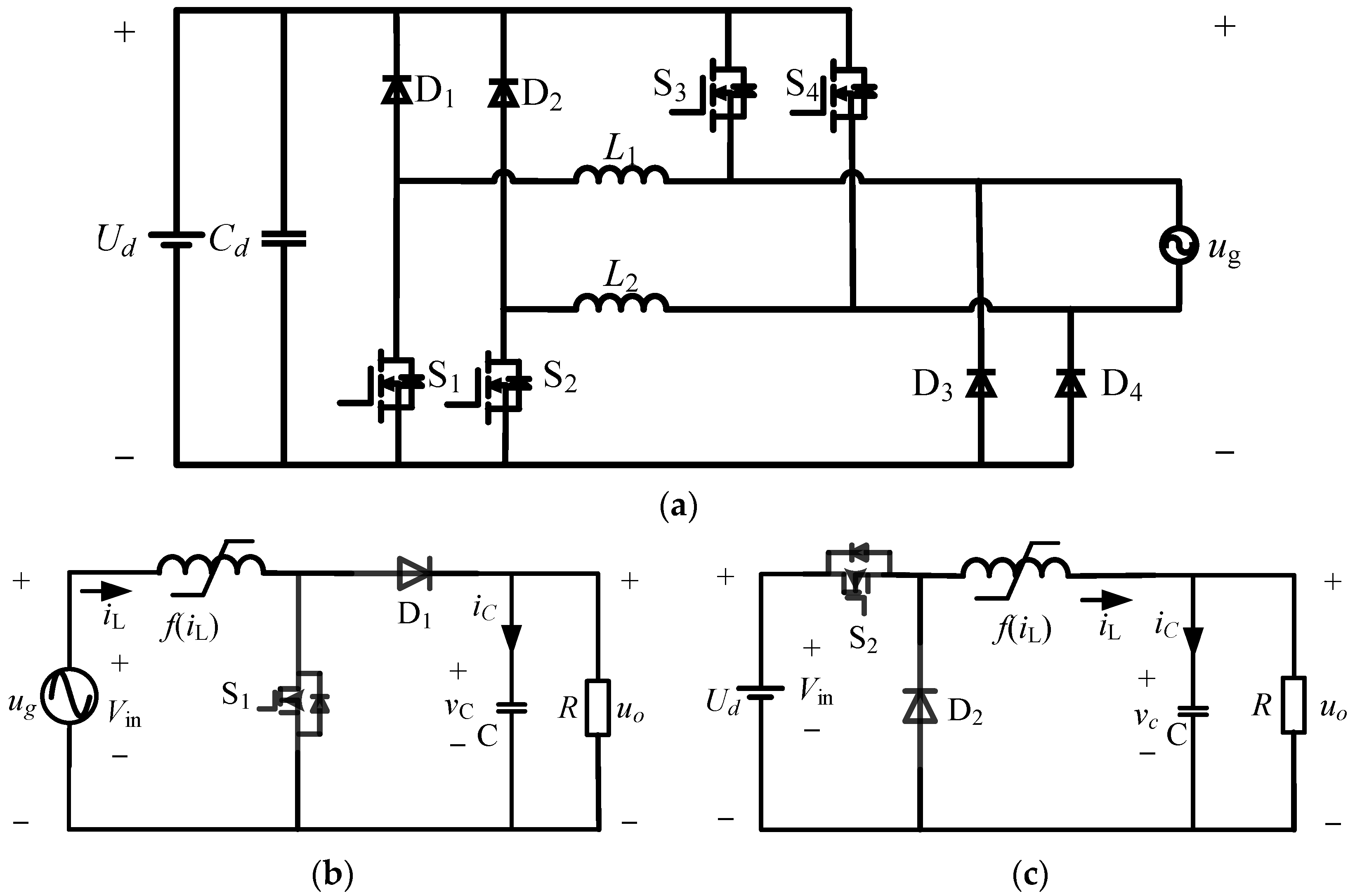
The dual-buck bi-directional converter solves the problems existing in the traditional bridge circuit structure [27], and its topology is shown in Figure 2a. ug is the voltage at the grid terminal and Uin is the DC bus voltage. The circuit is topologically equivalent to a collection of two buck circuits: Uin passes through the regulator filter capacitor Cd, diodes D1, inductor L1 and power switches S1 and S4 to form the first buck circuit, and diodes D2, inductor L2 and power switches S2 and S3 to form the other buck circuit. S1 and S2 are high-frequency MOS power switches and S3 and S4 are two industrial-frequency (50 Hz) power switches that can be designed as zero-current switches. In addition, the operation modes of the bi-directional converter can be categorized into rectifier and inverter. The bi-directional converter judges the operation mode according to the bus voltage state, achieving bi-directional flow of power and power factor correction in the rectifier mode and reliable grid-connected operation in the inverter mode. When the converter is in rectifier mode, it is divided into four modes, as shown in Table 1, in a complete industrial frequency sinusoidal waveform. The circuit is symmetrical and equivalent to a dual-boost circuit under positive and negative half-cycle of AC voltage input. Its boost equivalent circuit for positive half-cycle is shown in Figure 2b. When the converter is in inverter mode, it is divided into four modes, as shown in Table 2. With the grid operating at positive and negative voltage half-cycles, the circuit loop is symmetrical and equivalent to a buck circuit. The buck equivalent circuit for positive half-cycle is shown in Figure 2c.
According to the state averaging method, the state space equations of the dual-buck converter in rectifier and inverter modes are shown in Equations (1) and (2). When the switch in the circuit is on, the inductor current iL and the circuit output voltage uo (Ud in rectifier and ug in inverter) are used as state vectors.
where d is the duty cycle of the switch and R is the load impedance. However, in the practical environment, due to the existence of the inductor nonlinearity problem, the state equations expressed in Equations (1) and (2) do not match the system. Therefore, it is necessary to express the state equations as a function (Equation (3)) of the inductance elements in the coefficient matrix.
2.2. Nonlinear Inductor Modeling
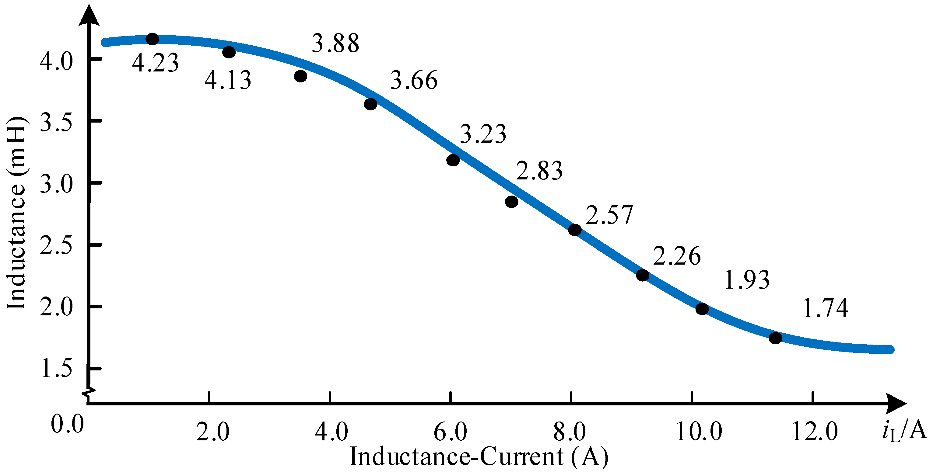
In actual systems, inductors are nonlinear electronic components. The nonlinear inductor is modeled based on the measured inductance data. The measured inductance curve with ferrite as the core material is shown in Figure 3, and the inductance value in the converter is updated by selecting the Lookup Table module in the MATLAB/Simulink (R2018b) environment to look up the table, taking the inductor current as the input and the inductance value obtained from Table 3 as the output.
2.3. Type-II T-S Fuzzy Modeling
In type-II fuzzy control, the designed membership degree is no longer an exact membership degree function as in type-I T-S. Type-II T-S fuzzy introduces more than one-dimensional coordinates to do the design of membership degree, and adds the consideration of the system uncertainty, which is much closer to the actual system, and has a greater degree of freedom in the design.
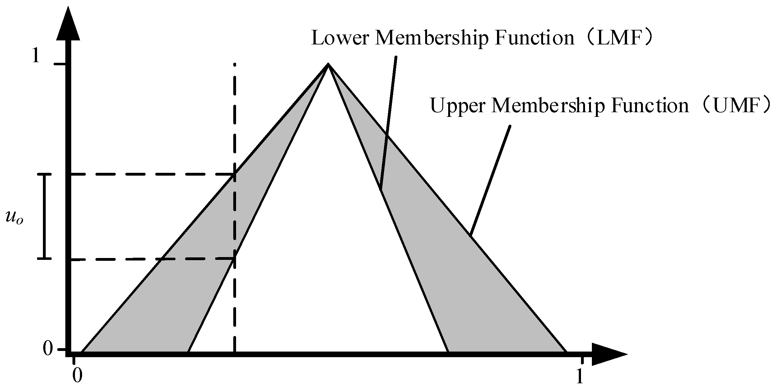
The main membership of a type-II T-S fuzzy system () is a “region” consisting of upper and lower membership functions that is shown in Equation (4), and the range embodied in the region is considered to be the uncertainty range of the system.
where denotes the function under rule I and denotes the lower membership function under rule i. In between, a segment of regionalized space is formed to represent the uncertainty of the system. The uncertainty of the nonlinear system is represented as shown in Figure 4.
Then, the weights of the corresponding subsystems are:
Thus, the global interval type-II T-S fuzzy can be defined as:
At each moment, the weighted sum of the membership corresponding to that moment is 1:
For the discrete type-II T-S fuzzy model, the same equation of state of the system is obtained as:
In the rectification mode of the bi-directional converter, the coefficient matrix in the dual-buck contains function terms, and the system is a nonlinear system. Therefore, the universal approximation ability of type-II T-S fuzzy is applied to describe the nonlinear bi-directional converter system, and the inductor current is used as an antecedent variable for fuzzification. To reduce the complexity of the operation and according to the PDC principle [28], the number of fuzzy rules is set to 2 and the domain of the inductor current iL is .
From the experimentally measured data, the main membership degree of type-II T-S fuzzy is designed. According to the introduction of the principle of type-II T-S fuzzy, the upper and lower membership of the main membership degree are set as:
Simultaneously, the sub-membership function is then introduced as a basis for judging the degree of uncertainty, since the amount of variation of the current can represent this uncertainty to a certain extent. In this paper, the method of designing the sub-membership of type II T-S fuzzy is that the wider the change in current per unit of time, the larger the uncertainty disturbance brought about, and it is considered that this disturbance is more pronounced when the current value is large. Therefore, the derivative of the inductor current regarding time is selected as the horizontal coordinate of the sub-membership to characterize the degree of uncertainty within the system in terms of the sub-membership function, whose type-II T-S fuzzy surface is shown in Figure 5.
The matrix of the type-II T-S fuzzy system in rectifier mode, , Equation (6) turns:
where the corresponding matrix parameters for the rectifier (Equation (11)) and inverter (Equation (12)) states are:
where the value of can be derived from the fuzzy rule surface to finally obtain a type-II T-S fuzzy model of the bi-directional converter in rectifier mode.
3. Control Strategy for Dual-Buck Bi-Directional Converter
3.1. Type-II T-S Fuzzy Controller Design
The basic idea of type-II T-S fuzzy is to design the number of fuzzy rules (number of fuzzy subsystems) for type-II fuzzy for a nonlinear system, determine the number of subcontrollers and design the controllers for each subsystem. Then each sub-controller is weighted by the membership function to get the synthesized sub-controller for each state. Firstly, assume that the localized state feedback controller is:
Controller Rule Ri:
Then,
where represents the state feedback control matrix under the ith system, and by defuzzification, the controller output is:
where and represent the upper and lower membership functions. And the corresponding weights of the upper and lower memberships are selected based on the sub-memberships, and the closed-loop control state equations consisting of the type-II fuzzy system and the controller are:
The rectifier mode II T-S fuzzy controller is designed as:
- Rule1: if iL = ILmin, then
- Rule2: if iL = ILmax, then
Therefore, the algorithmic expression for type-II T-S fuzzy controller in rectification mode (where uo is Ud and ui is ug) is:
In inverter mode (where uo is ug and ui is Ud), the algorithmic expression is:
3.2. Voltage Outer Loop Design
For a bi-directional converter, no matter which mode it is operating in, the ultimate goal is to make the converter run stable. By adding a voltage loop to control the DC side voltage of the system, the system can be enabled to operate normally and healthily despite load fluctuations. The expression for the network side current is:
where G is the conductance and ig is a sinusoidal AC current with frequency 50 Hz and amplitude Gug. The instantaneous input power at the grid side of the converter is:
From the input instantaneous power of Equation (24), it can be seen that if the input and output power are considered to be equal, then the output power components contain secondary ripples, that is, AC quantities with 100 Hz frequency components which are superimposed on the DC side. With the feedback process, the secondary component is superimposed on the working frequency (50 Hz), which makes the grid-side current contain the third harmonic component, leading to the degradation of the waveform quality, the increase of the distortion rate and even the loss of the conditions for grid connection, which results in the system not working properly.
Therefore, a closed-loop PI controller needs to be designed to suppress the secondary ripple and improve the waveform quality. The parameters of the controller are selected so that the gain at two times frequency is small enough to minimize the effect of secondary ripple. The voltage loop open loop transfer function is designed as:
where Po is the output power. For the secondary ripple of the system at 100 Hz, the controller of the voltage loop is designed to traverse a frequency of 1/10 twice the industrial frequency: fc = 10 Hz. Equation (26) can then be obtained.
Then, Kup = 0.0169 and Kui = 1.0619 can be obtained, and in order to be applied to the digital embedded system, the incremental PI controller is discretized with Equation (27):
where and represent the voltage error and the duty cycle of the kth switching cycle, respectively. represents the switching cycle. Thus, the expression of the PI controller is set as:
4. Results
4.1. Simulation Analysis
In order to verify the validity of the above theoretical analysis and controller design, this section establishes type-I and type-II T-S fuzzy models for simulation verification, and the simulation parameters are shown in Table 4.
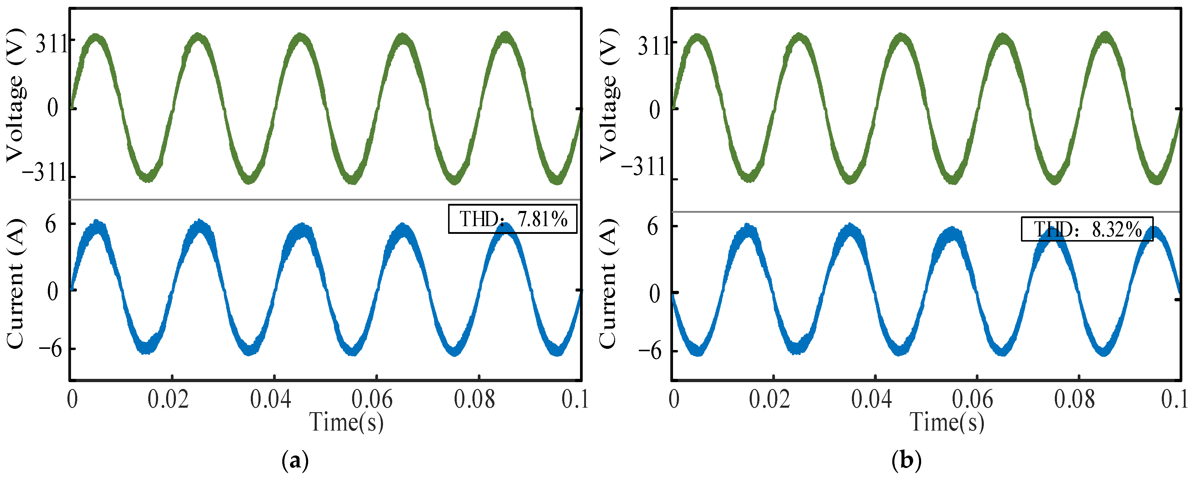
When the dual-buck bi-directional converter is considered with both inductor nonlinearity and system uncertainty factors (noise under Gaussian distribution as interference source in simulation), the simulation of a type-I T-S fuzzy controller is shown in Figure 6a,b. Figure 6a shows the control waveforms operating in rectifier mode and Figure 6b shows the waveforms in inverter mode. The THDs obtained from fast Fourier transform analysis in Simulink are 7.81% and 8.32% for rectifier and inverter mode, respectively. Since the sampled current contains uncertainty, which leads to the suboptimal effect of the type-I T-S fuzzy control, the distortion rate of the system current waveform is still high, which does not satisfy the requirements of the system.
Figure 7 show the system current waveforms of the system under type II T-S fuzzy control running in the rectifier and inverter processes, and their THDs are 3.58% and 3.92%, respectively. Compared with the type I T-S fuzzy control, the type II T-S fuzzy control works better than the type I T-S fuzzy control in the environment of external interference, and the type II T-S fuzzy not only enables the system to solve the problem of low control performance caused by nonlinearity, but also can be better applied to the operating environment with large uncertainty.
4.2. Experimental Validation
In this section, based on the previous theoretical derivation and simulation verification, an experimental prototype platform of a dual-buck bi-directional converter with 1000 W power was designed, and the results obtained were analyzed and discussed. The setup environment is shown in Figure 8, including a power distribution cabinet as ug, host computer, voltage regulator, dual-buck bi-directional converter, DC source, electronic load to simulate half-load, full-load, and non-linear loads, and an oscilloscope for observing and recording experimental results.
On the experimental prototype of dual-buck bi-directional converter, the main circuit in the hardware includes the main power circuit, control circuit and auxiliary circuit. The overall design scheme of the experiment is shown in Figure 9. A 32-bit high-resolution TMS320F28377D chip from Texas Instruments was used as the digital control chip, which sampled the grid-side current/voltage and DC-side bus voltage and performed real-time duty cycle calculations. Then, the opto-coupler-isolated PWM signal was output to control the power switches of the main power circuit. The experimental prototype system parameters of the dual-buck bi-directional converter are shown in Table 5. The detailed parameter design and software design process are described in the following.
The analysis of the effect of the conventional single-cycle PI controller is first carried out under the conventional single-cycle control. As shown in Figure 10, due to the presence of nonlinear inductors and the interference of uncertainty factors, the control performance of the conventional controller is degraded, and the waveform quality of the inductor current is poor with the presence of high harmonics.
After adding the type-II T-S fuzzy single-cycle for control, the experimental waveforms under different powers are shown in Figure 11, where Figure 11a is the rectified experimental waveform under light load, Figure 11b is the rectified waveform under half-load and Figure 11c,d are the rectified and inverted waveforms under the full-load condition, respectively. Comparing with the effect of the control of the traditional single-cycle, the waveforms of the system under the control of type-II T-S fuzzy single-cycle are better and meet the low distortion requirements.
The dynamic response part (load switching) was added to verify the control effect of the voltage loop, and the waveforms are shown in Figure 12. The load-cutting experiments of inverter and rectifier were carried out respectively, and the waveforms prove that when the load is perturbed, the PI voltage outer loop of the dual-buck bi-directional DC-AC converter is able to respond to the changes in the load side quickly, with good robustness, and satisfy the characteristics of the output voltage stabilization under the load changes.
The dual-buck bi-directional converter system with a nonlinear inductor was working using the type-II T-S fuzzy control. The experimental results are shown in Figure 13. As can be seen from Figure 13a,c,e, the system is in the rectifier operating state; at this point, the power switches S3 and S4 are off and S1 and S2 are in the positive and negative half-cycle of the high-frequency operation, respectively. When S1 is on and S2 is off, withstand-voltage switch US1 and diode UD4 is 0. In the inverter state, as shown in Figure 13b,d,f, the switches S1 and S2 are working at high frequency to ensure the sinusoidalizing of the current, and S3 and S4 are switches under the control of the PWM frequency to form a connected circuit loop. When switches S2 and S3 are on and switches S1 and S4 are off, withstand-voltage switch US4 and diode UD4 are 0, which is in accordance with the operation principle of the dual-buck bi-directional DC-AC circuits.
Therefore, the proposed method has good applicability to the nonlinear inductance and the uncertainty of the system, and solves the problem of low control performance caused by the nonlinear inductance and the uncertainty factors. With the proposed method, the output waveform quality of the system is higher, and the aberration rate is greatly reduced, which satisfies the operating conditions of low aberration rate and high-power factor.
5. Conclusions
In this paper, with the dual-buck bi-directional converter, a type-II T-S fuzzy control strategy based on a single-cycle inner loop and a voltage outer loop is proposed. The nonlinear characteristics of the inductor and the uncertainties existing in the real system are studied. Both simulation and experimental verifications are carried out. According to the simulation results, it shows that under the condition of noise interference, the harmonic components of the current waveform quality are still very large under the type-I T-S fuzzy control, which fails to meet the requirements of grid connection. The type-II T-S fuzzy control, on the other hand, has better control performance than the type-I T-S fuzzy under high uncertainty environment due to the robustness of its membership function with certain degrees of freedom. It enables the system to operate healthily under the condition of meeting the requirements. The control effect of type-II T-S fuzzy control is also verified on an experimental prototype with a power of 1 kW. It is proved that the algorithm has good applicability to the system with uncertainty and nonlinear inductance conditions. The problem of low control performance caused by nonlinear inductance as well as uncertainties is solved, and the quality of the output waveform is improved to meet the system’s grid-connection requirements.
Author Contributions
Z.C. methodology, software, data curation and writing—original draft; R.H. methodology, data curation and writing—review and editing; Q.L. resources, writing—review and editing supervision and funding acquisition; X.Y. conceptualization, visualization and funding acquisition; Z.D. validation, investigation, resources and data curation. All authors have read and agreed to the published version of the manuscript.
Funding
This work was supported by the Science and Technology Major Project of Fujian Province of China under Grant 2022HZ028010.
Data Availability Statement
The data that support the findings of this study are available from the corresponding author upon reasonable request.
Conflicts of Interest
Author Zhimin Dan was employed by the company Contemporary Amperex Technology Co., Limited. The remaining authors declare that the research was conducted in the absence of any commercial or financial relationships that could be construed as a potential conflict of interest.
References
- Yang, Y.; Pan, J.Y.; Wen, H.Q.; Fan, M.D.; Chen, R.; He, L.Q.; Xie, M.X.; Norambuena, M.; Xu, L.Y.; Rodriguez, J. Model Predictive Current Control with Low Complexity for Single-Phase Four-Level Hybrid-Clamped Converters. IEEE Trans. Transp. Electrif. 2021, 7, 983–999. [Google Scholar] [CrossRef]
- Habib, S.; Khan, M.M.; Abbas, F.; Sang, L.; Shahid, M.U.; Tang, H. A Comprehensive Study of Implemented International Standards, Technical Challenges, Impacts and Prospects for Electric Vehicles. IEEE Access 2018, 6, 13866–13890. [Google Scholar] [CrossRef]
- Zhang, R.Q.; Cheng, X.; Yang, L.Q. Flexible Energy Management Protocol for Cooperative EV-to-EV Charging. IEEE Trans. Intell. Transp. Syst. 2019, 20, 172–184. [Google Scholar] [CrossRef]
- Bibak, B.; Tekiner-Mogulkoc, H. Influences of Vehicle to Grid (V2G) On Power Grid: An Analysis by Considering Associated Stochastic Parameters Explicitly. Sustain. Energy Grids Netw. 2021, 26, 100429. [Google Scholar] [CrossRef]
- Chen, Y.W.; Jiang, Z.Y.; Wei, L.Q.; Feng, W.; Zhang, Y.J.; Jiang, J.H. An Asymmetric Full-bridge Bidirectional DC-AC Converter with Power Decoupling and Common-mode Current Suppression for V2G Application. IEEE J. Emerg. Sel. Top. Power Electron. 2024; early access. [Google Scholar] [CrossRef]
- Yang, F.; Ge, H.G.; Yu, Z.L.; Li, Y.; Wu, H.F. Topology and Control of Four-Quadrant Dual-DC-Port Dual-Buck Inverters for Semi-Two-Stage DC–AC Power Conversion. IEEE Trans. Ind. Electron. 2021, 68, 10718–10729. [Google Scholar] [CrossRef]
- Le, T.-T.; Lee, J.; Choi, S. Single-Stage Totem-Pole AC–DC Converter Based on Boost Half-Bridge Structure for Battery Chargers. IEEE Trans. Power Electron. 2024, 39, 1060–1073. [Google Scholar] [CrossRef]
- Koushki, B.; Jain, P.; Bakhshai, A. Half-Bridge Full-Bridge AC–DC Resonant Converter for Bi-Directional EV Charger. IEEE Access 2023, 11, 78737–78753. [Google Scholar] [CrossRef]
- Santis, V.D.; Francesco, A.D.; D’Aloia, A.G. A Numerical Comparison between Preisach, J-A and D-D-D Hysteresis Models in Computational Electromagnetics. Appl. Sci. 2023, 13, 5181. [Google Scholar] [CrossRef]
- Oliveri, A.; Lodi, M.; Storace, M. Nonlinear Models of Power Inductors: A Survey. Int. J. Circuit Theory Appl. 2022, 50, 2–34. [Google Scholar] [CrossRef]
- Scirè, D.; Lullo, G.; Vitale, G. Assessment of the Current for a Non-Linear Power Inductor Including Temperature in DC-DC Converters. Electronics 2023, 12, 579. [Google Scholar] [CrossRef]
- Safamehr, H.; Najafabadi, T.A.; Salmasi, F.R. Enhanced Control of Grid-Connected Inverters with Non-Linear Inductor in LCL Filter. IET Power Electron. 2016, 9, 2111–2120. [Google Scholar] [CrossRef]
- Sgrò, D.; Correia, W.B.; Leão, R.P.S.; Tofoli, F.L.; Tibúrcio, S.A.S. Nonlinear Current Control Strategy for Grid-Connected Voltage Source Converters. Int. J. Electr. Power Energy Syst. 2022, 142, 108349. [Google Scholar] [CrossRef]
- Yao, Z.G.; Lan, H.G.; He, X.Y.; Deng, F.; Wang, C.S.; Lu, S.; Tang, Y. Nonlinear Inductor-Based Single Sensor Current Balancing Method for Interleaved DC–DC Converters. IEEE Trans. Power Electron. 2024, 39, 3996–4000. [Google Scholar] [CrossRef]
- Yin, L.; Chen, Z.F.; Liu, J. Nonlinear Behavior Mechanism and Modeling Method of Wound SMD Inductor. Int. J. Numer. Model. 2023, 36, 1. [Google Scholar] [CrossRef]
- Molina-Santana, E.; Gonzalez-Montañez, F.; Liceaga-Castro, J.U.; Jimenez-Mondragon, V.M.; Siller-Alcala, I. Modeling and Control of a DC-DC Buck–Boost Converter with Non-Linear Power Inductor Operating in Saturation Region Considering Electrical Losses. Mathematics 2023, 11, 4617. [Google Scholar] [CrossRef]
- Divac, S.; Rosić, M.; Zurek, S.; Koprivica, B.; Chwastek, K.; Vesković, M. A Methodology for Calculating the R-L Parameters of a Nonlinear Hysteretic Inductor Model in the Time Domain. Energies 2023, 16, 5167. [Google Scholar] [CrossRef]
- Yang, X.; Yang, J.F.; Fan, J.; Wang, B.; Li, D.Z. A Position-Insensitive Nonlinear Inductive Power Transfer System Employing Saturable Inductor. Energies 2023, 16, 2430. [Google Scholar] [CrossRef]
- Hong, F.; Liu, J.; Ji, B.J.; Zhou, Y.F.; Wang, J.H.; Wang, C.H. Single Inductor Dual Buck Full-Bridge Inverter. IEEE Trans. Ind. Electron. 2015, 62, 4869–4877. [Google Scholar] [CrossRef]
- Viana, C.C.D.; Soong, T.; Lehn, P.W. Single-Input Space Vector Based Control System for Ripple Mitigation on Single-Phase Converters. IEEE Trans. Power Electron. 2019, 34, 3765–3774. [Google Scholar] [CrossRef]
- Liu, B.; Zhang, Z.G.; Li, G.J.; He, D.Q.; Chen, Y.M.; Zhang, Z.R.; Li, G.; Song, S.J. Integration of Power Decoupling Buffer and Grid-Tied Photovoltaic Inverter with Single-Inductor Dual-Buck Topology and Single-Loop Direct Input Current Ripple Control Method. Int. J. Electr. Power Energy Syst. 2021, 125, 106423. [Google Scholar] [CrossRef]
- Castillo, O.; Melin, P. A Review on Interval Type-2 Fuzzy Logic Applications in Intelligent Control. Inf. Sci. 2014, 279, 615–631. [Google Scholar] [CrossRef]
- Rong, N.N.; Wang, Z.S.; Zhang, H.G. Finite-Time Stabilization for Discontinuous Interconnected Delayed Systems via Interval Type-2 T–S Fuzzy Model Approach. IEEE Trans. Fuzzy Syst. 2019, 27, 249–261. [Google Scholar] [CrossRef]
- Yang, X.Z.; Lam, H.K.; Wu, L.G. Membership-Dependent Stability Conditions for Type-1 And Interval Type-2 T–S Fuzzy Systems. Fuzzy Sets Syst. 2019, 356, 44–62. [Google Scholar] [CrossRef]
- Zhao, J.; Xiao, Y.; Liang, Z.C.; Wong, P.K.; Xie, Z.C.; Ma, X.G. Adaptive Event-Triggered Interval Type-2 T-S Fuzzy Control for Lateral Dynamic Stabilization of AEVs With Intermittent Measurements and Actuator Failure. IEEE Trans. Transp. Electrif. 2023, 9, 254–265. [Google Scholar] [CrossRef]
- Liu, C.; Wu, J.X.; Yang, W.D. Robust Control for Interval Type-2 T-S Fuzzy Discrete Systems with Input Delays and Cyber Attacks. J. Syst. Sci. Complex. 2023, 36, 1443–1462. [Google Scholar] [CrossRef]
- Cui, Y.L.; Wang, Y.F.; Ma, X.Y. Parameters Design and Optimization of a High Frequency, Interleaved, Dual-Buck, Bidirectional, Grid-Connected Converter. Electronics 2019, 8, 973. [Google Scholar] [CrossRef]
- Yousef, M.Y.; Mosa, M.A.; Ali, A.A.; Ghany, A.M.A.; Ghany, M.A.A. Load Frequency Control for Power System Considering Parameters Variation Using Parallel Distributed Compensator Based on Takagi-Sugino Fuzzy. Electr. Power Syst. Res. 2023, 220, 109352. [Google Scholar] [CrossRef]
Figure 1.
Bi-directional converter in V2G.

Figure 2.
Converter circuit topology. (a) Dual-buck bi-directional converter; (b) positive half-circle rectifier equivalent circuit; (c) positive half-circle inverter equivalent circuit.
Figure 2.
Converter circuit topology. (a) Dual-buck bi-directional converter; (b) positive half-circle rectifier equivalent circuit; (c) positive half-circle inverter equivalent circuit.

Figure 3.
Actual inductance measurement curve with ferrite as core material.

Figure 4.
Main membership degree function diagram.

Figure 5.
Type-II T-S fuzzy curve diagram.

Figure 6.
T-S fuzzy waveform of type I. (a) Rectification mode; (b) inverter mode.

Figure 7.
Waveform of type-II T-S fuzzy. (a) Rectification mode; (b) inverter mode.

Figure 8.
Prototype experimental environment.

Figure 9.
Overall design scheme of the experiment.

Figure 10.
Conventional single-cycle control output waveforms. (a) Rectifier; (b) inverter.

Figure 11.
Type-II T-S fuzzy single-cycle control waveform under different power. (a) Light-load (200 W) rectified waveforms, THDi = 4.0%; (b) half-load (500 W) rectified waveform, THDi = 2.2%; (c,d) full-load (1000 W) rectified/inverter waveform, THDi = 2.6%/THDi = 2.7%, respectively.
Figure 11.
Type-II T-S fuzzy single-cycle control waveform under different power. (a) Light-load (200 W) rectified waveforms, THDi = 4.0%; (b) half-load (500 W) rectified waveform, THDi = 2.2%; (c,d) full-load (1000 W) rectified/inverter waveform, THDi = 2.6%/THDi = 2.7%, respectively.

Figure 12.
Dynamic waveforms. (a) Rectifier and (b) inverter cut load current waveform.

Figure 13.
Rectifier/inverter grid-connected experiment steady state waveforms. (a,b) Driving waveforms of switchers; (c,d) withstand-voltage waveforms of the S1 and S4; (e,f) corresponding D1 and D4 withstand-voltage waveforms.
Figure 13.
Rectifier/inverter grid-connected experiment steady state waveforms. (a,b) Driving waveforms of switchers; (c,d) withstand-voltage waveforms of the S1 and S4; (e,f) corresponding D1 and D4 withstand-voltage waveforms.


Table 1.
Rectifier operating modes.
| ug | Mode | S1 | S2 | S3 | S4 | D1 | D2 | D3 | D4 |
|---|---|---|---|---|---|---|---|---|---|
| >0 | 1 | 1 | 0 | 0 | 0 | 0 | 0 | 0 | 1 |
| 2 | 0 | 0 | 0 | 0 | 1 | 0 | 0 | 1 | |
| <0 | 3 | 0 | 1 | 0 | 0 | 0 | 0 | 1 | 0 |
| 4 | 0 | 0 | 0 | 0 | 0 | 1 | 1 | 0 |
Table 2.
Inverter operating modes.
| ug | Mode | S1 | S2 | S3 | S4 | D1 | D2 | D3 | D4 |
|---|---|---|---|---|---|---|---|---|---|
| >0 | 1 | 0 | 1 | 1 | 0 | 0 | 0 | 0 | 0 |
| 2 | 0 | 0 | 1 | 0 | 0 | 1 | 0 | 0 | |
| <0 | 3 | 1 | 0 | 0 | 1 | 0 | 0 | 0 | 0 |
| 4 | 0 | 0 | 0 | 1 | 1 | 0 | 0 | 0 |
Table 3.
Inductance values under different current values.
| I (A) | L (mH) | I (A) | L (mH) | I (A) | L (mH) | I (A) | L (mH) |
|---|---|---|---|---|---|---|---|
| 1 | 4.23 | 6 | 2.83 | 11 | 1.54 | 16 | 0.83 |
| 2 | 4.13 | 7 | 2.57 | 12 | 1.35 | 17 | 0.74 |
| 3 | 3.88 | 8 | 2.26 | 13 | 1.19 | 18 | 0.66 |
| 4 | 3.66 | 9 | 1.96 | 14 | 1.05 | 19 | 0.60 |
| 5 | 3.23 | 10 | 1.71 | 15 | 0.93 | 20 | 0.55 |
Table 4.
Simulation parameters of bi-directional DC-AC converter.
| Parameters | Value |
|---|---|
| DC Voltage Reference | 380 V |
| Grid Voltage | 220 V/50 Hz |
| Switching Frequency | 40 kHz |
| Rated Power | 1000 W |
| Filter Capacitance | 1 mF |
Table 5.
Design parameters of prototype.
| Parameters | Value |
|---|---|
| DC Voltage Reference | 360 V |
| Rated AC Voltage/Frequency | 220 V/50 Hz |
| Rated Power | 1000 W |
| Switching Frequency | 40 kHz |
| Filter Inductance | 3 mH |
| DC-Side Bus Capacitance | 1 mF/450 V |
| Power Switch | MOSEFT SPW24N60C3 (Voltage Withstand: 650 V, Current Withstand: 24 A) |
| Diode | STTH1212D (Reverse Breakdown Voltage Maximum: 1200 V, Current Withstand: 12 A) |
Disclaimer/Publisher’s Note: The statements, opinions and data contained in all publications are solely those of the individual author(s) and contributor(s) and not of MDPI and/or the editor(s). MDPI and/or the editor(s) disclaim responsibility for any injury to people or property resulting from any ideas, methods, instructions or products referred to in the content. |
© 2024 by the authors. Licensee MDPI, Basel, Switzerland. This article is an open access article distributed under the terms and conditions of the Creative Commons Attribution (CC BY) license (https://creativecommons.org/licenses/by/4.0/).
Share and Cite
MDPI and ACS Style
Chen, Z.; Huang, R.; Lin, Q.; Yu, X.; Dan, Z. Nonlinear Modeling and Control Strategy Based on Type-II T-S Fuzzy in Bi-Directional DC-AC Converter. Electronics 2024, 13, 1684. https://0-doi-org.brum.beds.ac.uk/10.3390/electronics13091684
AMA Style
Chen Z, Huang R, Lin Q, Yu X, Dan Z. Nonlinear Modeling and Control Strategy Based on Type-II T-S Fuzzy in Bi-Directional DC-AC Converter. Electronics. 2024; 13(9):1684. https://0-doi-org.brum.beds.ac.uk/10.3390/electronics13091684
Chicago/Turabian StyleChen, Zhihua, Ruochen Huang, Qiongbin Lin, Xinhong Yu, and Zhimin Dan. 2024. "Nonlinear Modeling and Control Strategy Based on Type-II T-S Fuzzy in Bi-Directional DC-AC Converter" Electronics 13, no. 9: 1684. https://0-doi-org.brum.beds.ac.uk/10.3390/electronics13091684
Note that from the first issue of 2016, this journal uses article numbers instead of page numbers. See further details here.