
Design of 2.5 Bit Programmable Metasurface Unit Cell for Electromagnetic Manipulation


1
National Key Laboratory of Microwave Imaging Technology, Aerospace Information Research Institute, Chinese Academy of Sciences, Beijing 100101, China
2
National Key Laboratory of Antennas and Microwave Technology, Xidian University, Xi’an 710071, China
*
Author to whom correspondence should be addressed.
Electronics 2024, 13(9), 1648; https://0-doi-org.brum.beds.ac.uk/10.3390/electronics13091648
Submission received: 26 January 2024
/
Revised: 10 April 2024
/
Accepted: 15 April 2024
/
Published: 25 April 2024
(This article belongs to the Special Issue RF/Microwave Device and Circuit Integration Technology)
Abstract
:Programmable metasurfaces are two-dimensional electromagnetic structures characterized by a low profile, conformability, and the ability to flexibly manipulate the amplitude and phase of electromagnetic waves. For high-quality beam scanning with the metasurface, it is essential that the metasurface possesses high-precision phase response quantization characteristics. This paper constructs a reflection-type metasurface unit cell featuring four P-I-N diodes and six operating states. To address the unit cell’s complexity and optimization challenges, we developed an automatic optimization algorithm, derived from the genetic optimization algorithm, for the metasurface unit cell. This algorithm was used to optimize a six-phase reflective 2.5 bit programmable metasurface cell operating at 5 GHz. The unit cell’s prototype was fabricated and measured to verify the design. Additionally, a metasurface comprising 16 × 16 unit cells was designed and simulated. The results highlight the metasurface unit cell’s excellent phase response quantization characteristics, and investigate the impact of quantization accuracy on beam scanning.
1. Introduction
Antennas, crucial components in wireless communication, facilitate the reception and transmission of radio waves. The rapid development of mobile communications has led to increased performance requirements for antennas. For instance, it is often desired for antennas to have high gain, good directionality, and beam scanning capabilities. In practical applications, reflector antennas offer efficient power utilization and high power capacity but suffer from large size and slow mechanical rotation for beam scanning, failing to meet the needs for high-speed scanning [1]. Phased array antennas enable electronically controlled beam scanning but require numerous expensive active transmitters and receivers (T/R components), limiting their widespread use [2].
Since the introduction of programmable (or reconfigurable) metasurfaces [3,4,5,6], both academia and industry have extensively explored their potential in applications such as wireless communication and remote sensing. Reconfigurable metasurfaces are typically made up of a spatial feeder and a reflective surface. The reconfigurable metasurface antenna manipulates the unit’s phase or amplitude response using electrically adjustable devices, such as diodes, which makes a metasurface antenna reconfigurable. Its reconfigurability grants it versatile manipulation capabilities. Independent control over the reflection or transmission of electromagnetic waves from the feeder to each metasurface unit enables flexible electromagnetic wave manipulation. This combination allows us to create a digitally programmable metasurface under the control of a field programmable gate array (FPGA), opening up a broad spectrum of application scenarios.
Compared to reflector antennas, electromagnetic metasurfaces offer the advantages of a low profile and easy deployment, thanks to their two-dimensional structure. They also enable beam scanning. Unlike phased array antennas, they require only a few active devices per unit cell to alter the amplitude–phase response for beam scanning, resulting in lower transmission loss in the feeding network. Moreover, programmable electromagnetic metasurfaces are generally produced using printed circuit board (PCB) technology, making them cost-effective compared to large-scale reflector or phased array antennas with complex devices. Electromagnetic metasurfaces can also enable applications like vortex wave generation [7,8], electromagnetic focusing [9,10], and holographic imaging [11,12], offering vast prospects in communication and beyond. Recently, reconfigurable metasurfaces have emerged as a highly active area of research.
The phase response quantization accuracy of the unit cell is an important metric in the design of metasurfaces. When forming the metasurface for beam scanning, the low quantization accuracy for smaller aperture arrays can cause an increase in the secondary flap, which in turn leads to gain loss and reduces the directivity of the antenna [13,14]. To circumvent these problems, a metasurface with high phase response quantization accuracy is required. Currently, there are two schemes to achieve high quantization accuracy; the first one is to use a varactor diode to achieve the high-accuracy quantization of the phase response by varying the bias voltage loaded on it [15,16,17]. However, the varactor diode introduces a large insertion loss and requires a large number of digital-to-analog converters (DACs) for control. Another approach is to achieve reconfigurability using discrete devices such as P-I-N diodes, which typically have low losses, stable phase states, and a simple bias network [18,19,20]. The use of P-I-N diode tuning schemes to achieve high quantization accuracy on the metasurface requires the placement of multiple P-I-N diodes, which leads to the complexity of the structure, making the design process difficult [21]. Until now, not many P-I-N diode loaded metasurface cell designs with more than 2 bit quantization accuracy have been proposed [22,23].
In this paper, a reflection-type programmable metasurface unit cell loaded with four P-I-N diodes with 2.5 bit operating states is proposed. It is quite difficult to optimize the phase response of metasurface cells with a large number of design variables. To solve this problem, here, we construct an automatic optimization algorithm based on the genetic optimization algorithm for unit cells and apply the algorithm to optimize the parameters of the proposed metasurface unit cell. Using the proposed method, we construct a reflective 2.5 bit programmable metasurface unit cell with an approximate 60° isotropic reflective phase response at the operating frequency of 5 GHz. The prototype of the unit cell is fabricated and measured using the waveguide measurements, and the measured results show that the proposed unit cell has good phase response quantization characteristics. To verity the advantages of the proposed unit cell, a reflective metasurface antenna array consisting of 256 cells for beam scanning application is formed and simulated using full-wave simulation. The effect of the quantization accuracy of the metasurface phase response on the beam scanning is discussed, and the results show that the high quantization accuracy of the unit cell has a significant effect on the reduction of the sidelobe. In addition, the results show that the high quantization accuracy of the unit cell has a certain effect on the improvement of the directivity of the metasurface antenna.
2. High-Quantitative-Accuracy Metasurface Unit Cell Modeling
Unit Design
The designed reflective metasurface unit cell is proposed to be tuned by a P-I-N diode modeled as SMP1345-079LF from SKYWORKS, Inc. (San Jose, CA, USA). We followed the methodology outlined in reference [24]. As a result, we were able to accurately determine the equivalent circuit parameters of the P-I-N diode when it was integrated into the metasurface cell, under electromagnetic wave incidence. According to measurement, the equivalent circuit of the P-I-N diode at 5 GHz is equivalent to a 3 Ω resistor in series with a 0.3 nH inductor for off status, and can be equivalent to a 10 Ω resistor in series with a 0.165 pF capacitor for on status. The equivalent circuit model is shown in Figure 1.
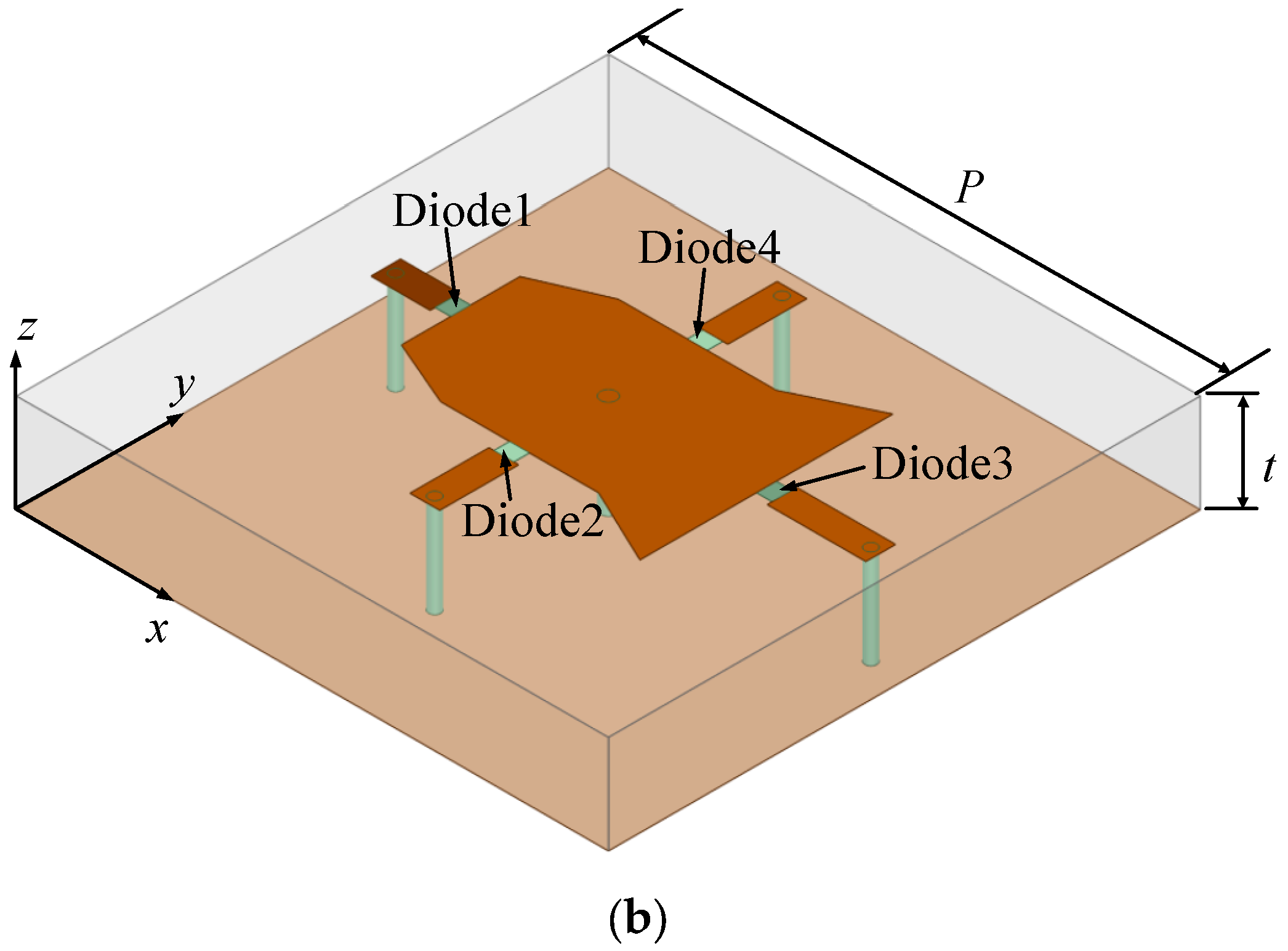
The three-dimensional view of the unit cell is shown in Figure 2a. The unit is designed to operate at a frequency of 5 GHz, using a F4B dielectric substrate with a thickness of 5 mm and a dielectric constant of 2.65. The size of the unit cell is set to be half the wavelength of the operating wavelength, i.e., 30 mm. The structure of the unit is symmetrically designed with respect to the x-axis so that it can modulate plane electromagnetic waves with x-polarization. The unit cell consists of a bottom metal layer, substrate, and top metal layer loaded with P-I-N diodes while the top metal layer consists of two trapezoidal and one rectangular patch. Four P-I-N diodes are loaded and each diode is connected to the metal patch at one end, and the other end is connected to a stub shorted to the ground through a metal via. The top layer metal patch also has a via designed under it to provide the DC bias. The unit has a wide range of adjustable parameters and is expected to realize 2.5-bit adjustable reflection phase. It is noted that the structure is supposed to realize 3 bit reflection phase; that is, diode 1 and diode 3 each can provide 1 bit adjustment freedom while diode 2, combined with diode 4, provides another 1 bit freedom. However, as the unit cell is x-polarized, the current on diode 2 and 4 is not strong, resulting in a weakness in the adjustment freedom. The top view of the cell and its structural parameters are shown in Figure 2b, where nine parameters, L1, L2, L3, H1, H2, H3, Line1_L, Line2_L, and Line3_L, will be used as tunable parameters for cell optimization.
Among them, the on-off status of the P-I-N diode will change the current distribution on the patch. Considering that the unit cell is only polarized for the x-direction, as shown in the figure, i.e., the induced current generated on the patch will be mostly distributed along the x-direction, the diode placed in the y-direction will have a weaker control over the current. Therefore, it is chosen to place two P-I-N diodes of the same operating state in the symmetric position about the x-axis to enhance the regulation of the cell by the y-direction P-I-N diode. The length of the short path is also adjustable, which allows the cell to reflect the electromagnetic wave in an adjustable path, further increasing the degree of freedom in the design of the metasurface unit cell.
The proposed metasurface cell has four diodes, in which the operating states of diode 2 and diode 4 are the same. Theoretically, the unit cell has a total of eight operating states. In this paper, we use the number “0” to indicate that the diode is on, and the number “1” indicate that the diode is off, with a 3 bit binary bit to indicate the operating state of the unit. The number of bits from high to low indicates the operating state of diode 1, diodes 2 and 4, and diode 3, respectively Based on this, the digital representation of the eight operating states of the diode is shown in Table 1.
3. Optimization Algorithm
The simulation modeling of programmable metasurface unit cell is the focus and difficulty in constructing reconfigurable metasurfaces, and its simulation mainly adopts the method based on equivalent circuits. The metasurface cells are often loaded with electrically tunable devices such as varactor diodes or P-I-N diodes for tuning to achieve specific radiation characteristics. We can simulate the unit cell by loading the equivalent circuits of these devices in the form of lumped components in electromagnetic simulation software. Unlike traditional electromagnetic structures such as antennas and waveguides, an electromagnetic metasurface unit cell has multiple operating states, and it is hard to obtain the simulation data for all operating states of the unit by solving the model of the unit in a single pass with a single electromagnetic simulation software. Electromagnetic full-wave simulation software algorithms generally take up large computer resources. The computing speed will be quite slow, if all the operating states of the unit are calculated, and then the simulation time of the unit will increase exponentially.
To solve this problem, a “multi-port network-based simulation method” was proposed [24]. This method of modeling and simulation of the metasurface is based on the combination of full-wave simulation and circuit simulation software, in which the electromagnetic simulation software is used to analyze the model of the unit and then loaded into the circuit simulation software. The data of each state of the unit cell can be obtained by a single-round electromagnetic modeling process. Aiming at the problem of the high phase response quantization accuracy of metasurface cells with many structural variables and difficult model optimization, an automatic optimization algorithm for electromagnetic metasurface cells based on the genetic optimization algorithm is constructed. In this section, an automatic optimization design algorithm for programmable metasurface unit cells is constructed, so that it can automatically optimize the structural parameters of the modeled cells to achieve the expected phase response quantization accuracy.
3.1. Genetic Optimization Algorithm
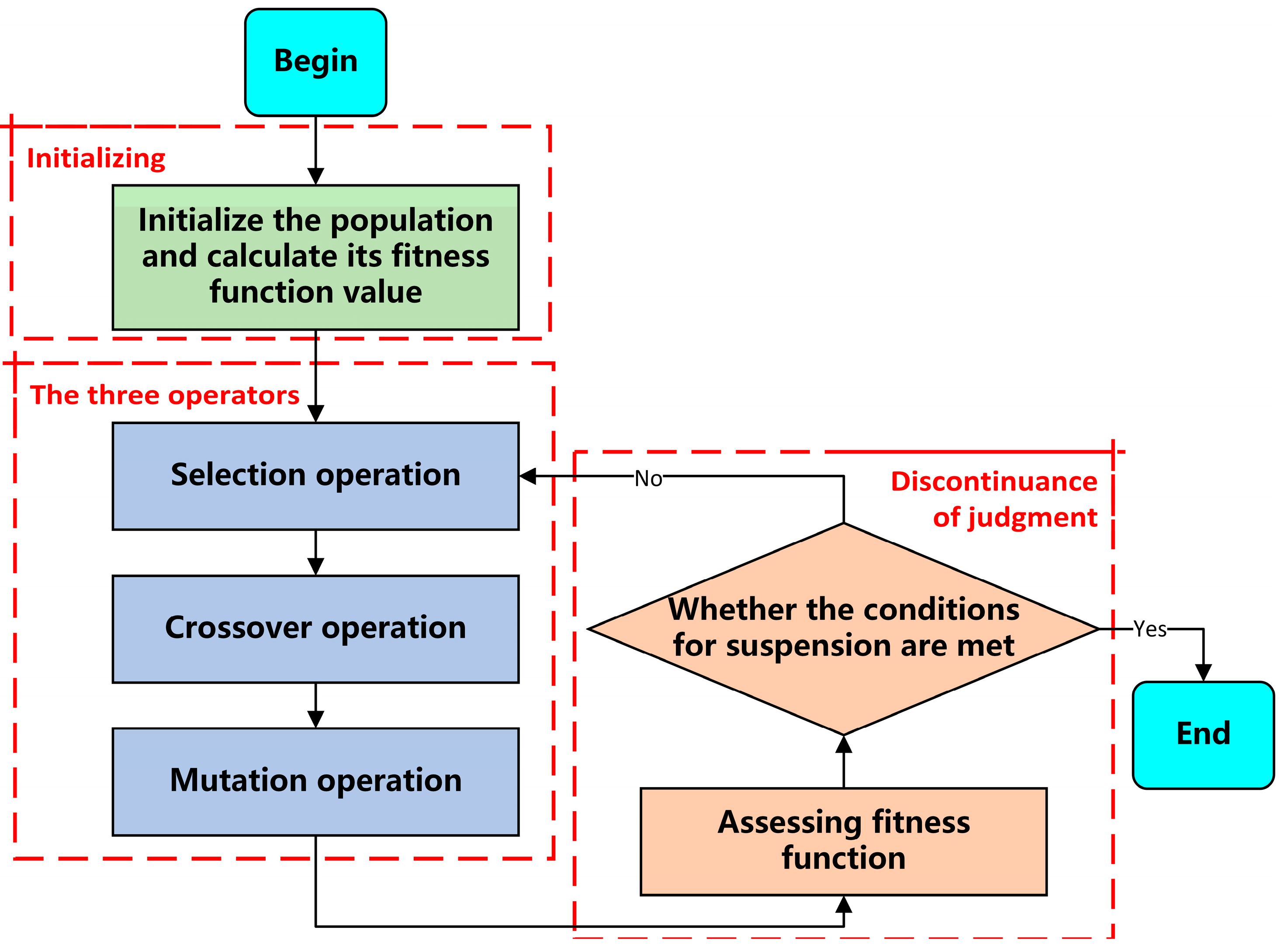
Genetic algorithm (GA) is an optimization algorithm based on the principle of biological evolution, which achieves problem solving by simulating the processes of heredity, mutation, and selection in nature. GA was originally proposed by John Holland in the 1970s [25], has and is now widely used in optimization problems in various fields. The basic principle of GA is to generate new individuals through the selection, crossover, and mutation of individuals in the current population to form the next generation of the population, and gradually optimize the quality of the solution. The flow block diagram of GA is shown in Figure 3.
Genetic optimization algorithms have the following advantages: firstly, GAs have strong global search ability, and their search process is based on global optimization, which can find the optimal solution in large-scale search space. Secondly, GAs do not need a special mathematical modeling of the problem, only rely on the fitness function value to optimize, without the need for derivative information, and can solve a variety of complex problems, such as nonlinear, nonconvex, and high-dimensional problems. In addition, GAs can be applied to multi-objective optimization problems. Common multi-objective GAs include Non-dominated Sorting Genetic Algorithm (NSGA), NSGA-II, Strength Pareto Evolutionary Algorithm (SPEA), and so on [26,27]. Genetic algorithm is widely used in practical engineering because of its wide range of applications and easy implementation, and the optimization algorithm constructed in this paper is proposed to use genetic optimization algorithm as the optimization algorithm.
3.2. Algorithmic Framework
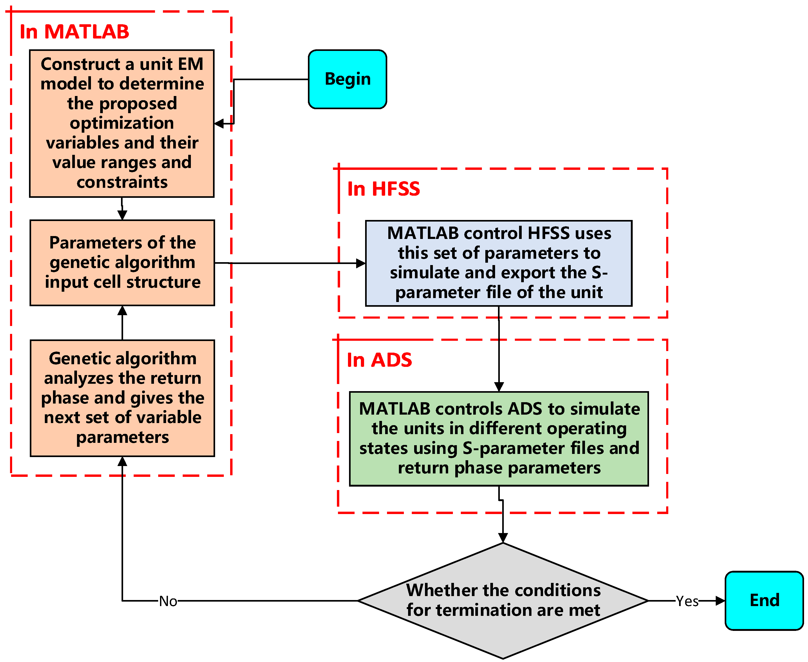
The simulation method of the metasurface cell used in the constructed algorithms is the multi-port network-based simulation method. The steps of the algorithm can be briefly summarized as follows. Firstly, the diode model is replaced with a lumped port using the full wave simulation software HFSS (version 2019) provided by ANSYS, and the Floquet port excitation and master-slave boundary conditions are set to simulate the cell. Secondly, Keysight ADS software (version 2019) reads the S-parameter file obtained from HFSS simulation, the equivalent RLC circuit models of diodes at high frequencies under different operating conditions are loaded at the corresponding ports, and then the constructed circuit models are simulated. By simulating the constructed circuit model, the reflection phases of the incident wave reflected by the metasurface unit under different operating states can be obtained simultaneously.
Figure 4 shows the main framework of the automatic optimization algorithm proposed in this paper. Under this framework, it is needed to solve the communication problems between MATLAB (version 2022a) and HFSS, and MATLAB and ADS software, i.e., to realize the call simulation and parameter return from MATLAB to HFSS and ADS software.
3.3. Design of the Fitness Function
For the reflective metasurface unit, we need to achieve the goal that the phase difference between two adjacent operating states of the metasurface unit is equal to the expected quantization phase response accuracy, so that the quantization error can be minimized. Therefore, we can sort the reflection phase data returned from the ADS in MATLAB, calculate the phase difference between two reflections in sequence, and take the value of the largest reflection phase difference as the value of the fitness function. The mathematical expression of the fitness function is shown in the following equation:
where fi(θ) is the phase response at the sorted operating frequency, the value of the phase response increases with the subscript 1~i, and q is the number of quantized phases.
f(θ) = max{|fi(θ) − fi−1(θ)|}
It can be seen that the minimum value of this fitness function is the quantization interval of the designed expected phase response. Then, when the individual fitness value in this optimization scenario is closer to the expected quantization interval, the value of the neighboring reflection phase difference of the unit is also closer to the exact quantization interval. Therefore, it is believed that the constructed fitness function can well guide the population in the genetic algorithm to evolve towards the target direction.
3.4. Algorithmic Implementation
Currently, HFSS software supports running .py script files written in Python language or .vbs script files generated by HFSS through recording operations. The design proposed in this paper intends to use MATLAB as the building platform for the algorithm, according to the open source project HFSS-MATLAB-API [28], successfully completing the MATLAB writing script and calling HFSS to run the script, realizing the control of HFSS by MATLAB.
The ADS software does not have an official executable script or program interface, and the automatic control of ADS can only be achieved through third-party program programming interfaces. Here, the automatic control of ADS software is realized by MATLAB using the open source project ADS-Matlab-Interface [29], The API is powerful enough to realize the parameter modification of the created circuit project file directly in MATLAB, call the simulator hpeesofsim of ADS software to simulate it, and read the simulation results in MATLAB.
After solving the problems of each part of the algorithm framework on the series, MATLAB provides the electromagnetic metasurface unit structure parameters, controls HFSS on the electromagnetic model simulation, and analyzes and exports the model S-parameter file, calling ADS’s simulator on the constructed circuit model; thus, the algorithm framework is constructed.
4. Optimization and Measurement Results
4.1. Metasurface Unit Optimization Results
Parameter optimization is performed for the reflective metasurface unit cell proposed in Section 2. In the optimization, the size of the population is set to 50. The fitness function is valued as the maximum of the reflection phase differences between the eight neighboring cell states, and the minimum of this function is solved by means of continuous iteration. In addition, to ensure that the model is built correctly, the upper and lower limits of the values of each parameter and the linear inequality constraints are also set. The run results obtained from the optimization are shown in Figure 5, which illustrates the average fitness of all individuals in the population in each generation, and the value of the fitness function for the optimal individual in the population in the current generation.
In the first few generations, both the mean value of the fitness function and the value of the fitness function of the optimal individual in each generation of the population declined rapidly. When the genetic algorithm was run to the 18th generation, it was observed that the optimal fitness decreased to 68.91°. The average fitness function value in the population slightly recovered in each generation from the 20th generation onwards, and there were no more optimal individuals appearing in the following iterations. In this case, it can be roughly estimated that the genetic algorithm has found the optimal solution in the search space. The unit corresponding to the current optimal individual of the fitness function is simulated, and its corresponding reflection phase curve is shown in Figure 6.
It can be observed that the phase curves of the unit in the eight operating states are not completely separated. The phase curves of states “000” and “010”, and states “101” and “111” are identical, which means that when diode 1 and diode 3 are on or off at the same time, the on and off status of diodes 2 and 4 has no effect on the reflective characteristics of the unit. The possible reason is that when diode 1 and diode 3 are on or off together, since the direction of the incident wave polarization is along the direction of the current flow on diode 1 and diode 3, most of the microwave currents on the metal iron sheet will also flow along that direction. Because diodes 2 and 4 can control the current flow in their orthogonal direction, the change of the reflective characteristics of the unit caused by the on and off status of diodes 2 and 4 is very limited. For this reason, we extract “001”, “010”, “011”, “100”, “101”, and “110” as the six operating states, and the metasurface unit cell is regarded as a six-phase equally spaced quantized reflective metasurface unit cell. The reflection phase values of each operating state at the operating frequency of 5 GHz are shown in Table 2.
The maximum error of the optimized cell’s reflection phase from the six-phase equidistant distribution is 18.79°, and the average error is 7.88°, which is 13.1% of the quantization of the standard six-phase reflection phase. The results indicate that the optimized metasurface unit cell is a reflective six-phase cell with good performance. The three-dimensional view of the cell structure is shown in Figure 7. The optimized numerical results are shown in Table 3.
4.2. Unit Measurement
To verify the design, the optimized metasurface unit cell is fabricated and measured using the waveguide measurement method. The waveguide was used to test this reflective six-phase metasurface unit, and the model constructed is shown in Figure 8. It consists of three layers of dielectric plates screwed tightly together, with the same dimensions as the waveguide flange used. The first layer of the dielectric plate consists of a gasket structure, and the unit size of the same slot and the surrounding metallized vias through holes construct a closed space, to ensure that the electromagnetic waves radiated by the waveguide are all illuminated on the patch of the unit. The second layer of the unit, that is, the metasurface unit, is moved to the side of the waveguide flange on the dielectric plate. The perimeter of the unit is also lined with metallized vias to ensure the radiating properties of the unit. In the third layer of the dielectric plate, fan-shaped branches are constructed and used to short-circuit microwave current to ensure that the electrical characteristics of the unit are not affected by the DC bias.
The WR187 waveguide is used to test the fabricated unit cell, using three independent power supplies for the diode plus DC bias, and can freely switch its operating state. By observing the S11 of the vector network analyzer, the reflective characteristics of the unit in different states can be viewed. Using the standard PCB technology, the prototype of the designed unit cell and the test structure are fabricated. The prototype of the test unit is shown in Figure 9a while the test environment is shown in Figure 9b.
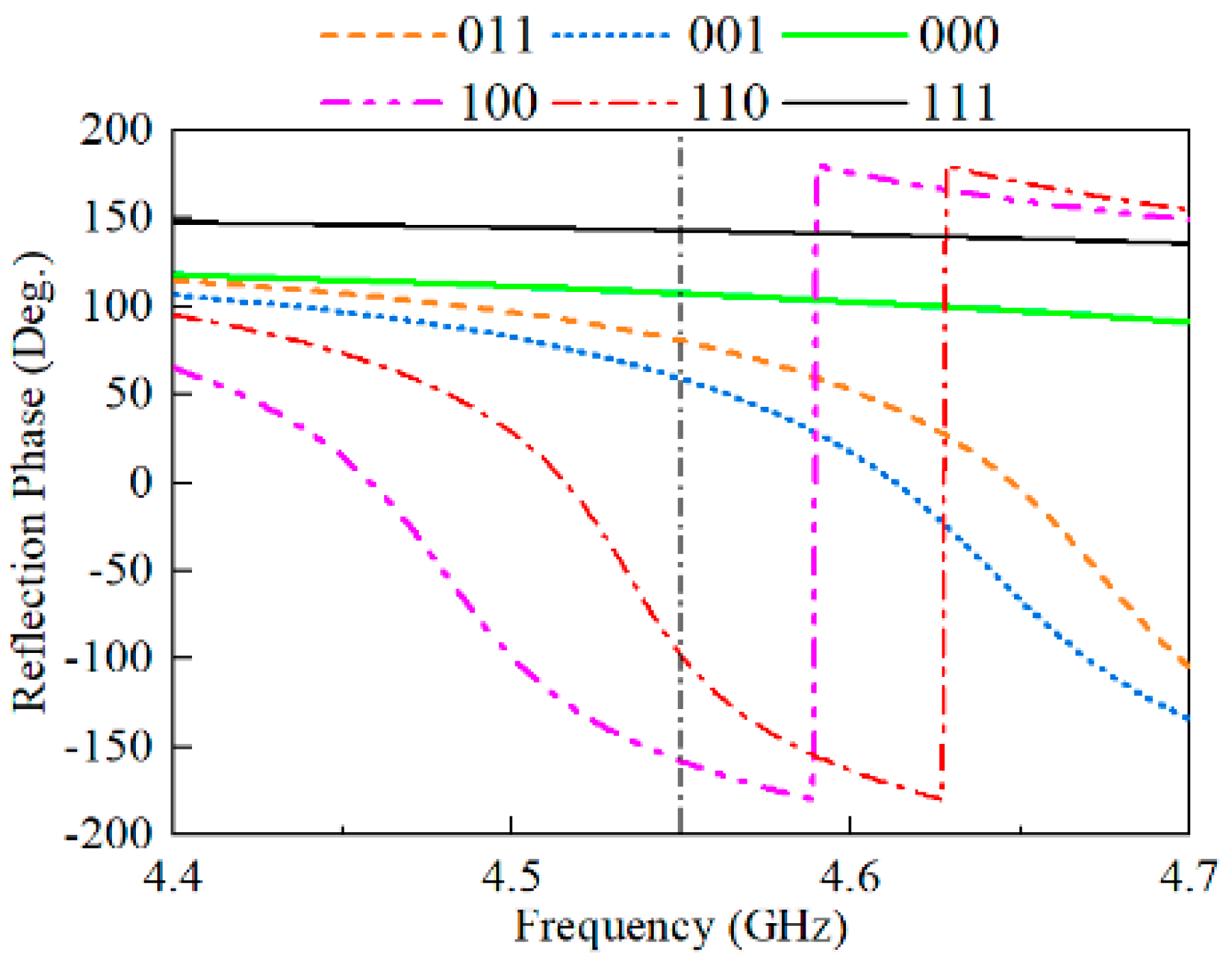
The phase response of the unit in different operating states obtained through experimental tests is shown in Figure 10. It can be observed that the unit has six-reflection-phase differentiation at the 4.55 GHz frequency point.
4.3. The Metasurface Antenna Design and Simulation Results
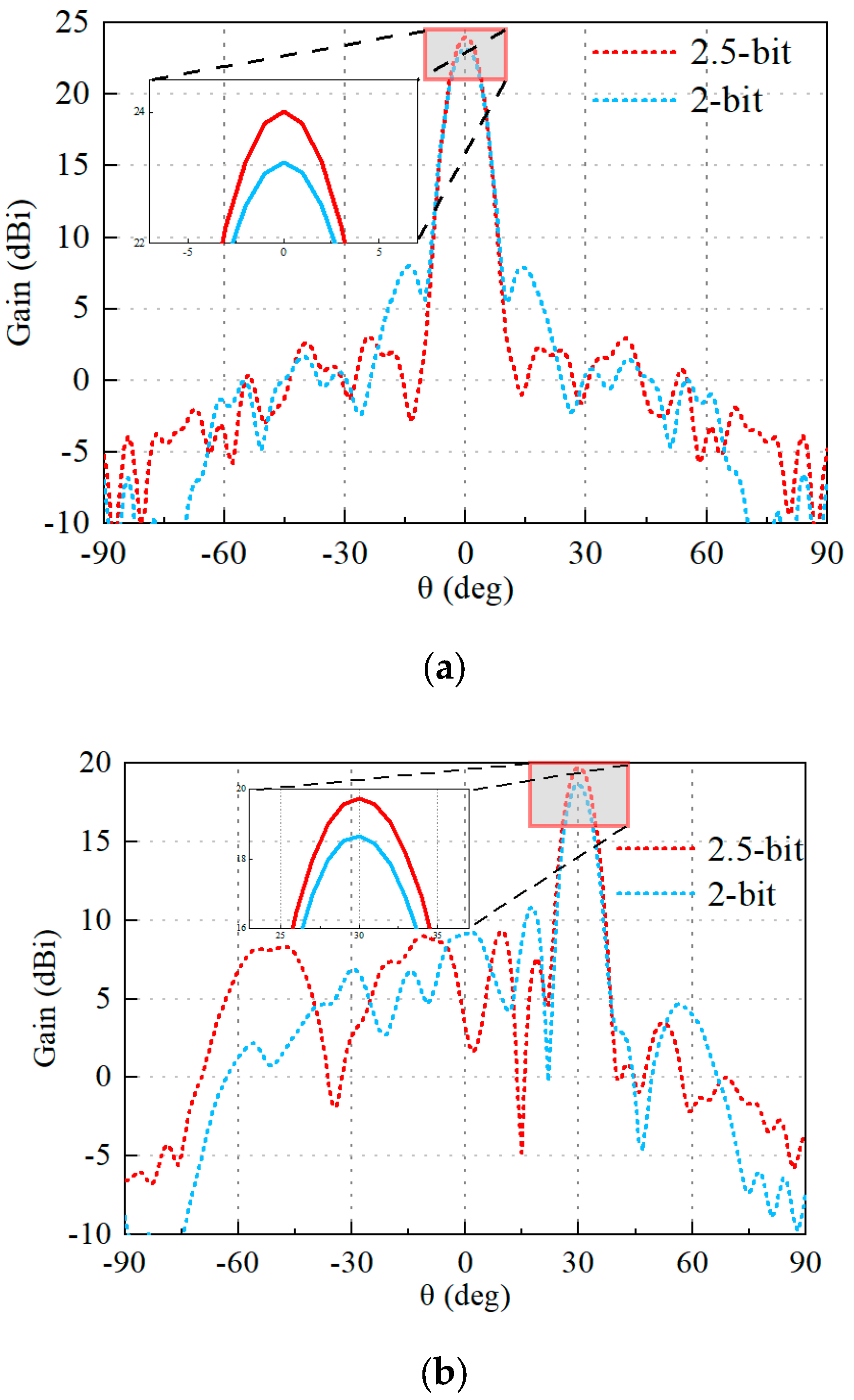
The cells are formed into a 16 × 16 metasurface antenna with horn feed and beam scanning application, as shown in Figure 11. The results of the simulation are shown in Figure 12. With reference to the figure, one can see that the constructed array has good beam scanning capability. In addition, a 2 bit unit cell, i.e., the four operating states of “100, 110, 011, 111”, is extracted to form another metasurface antenna for comparison with that using the 2.5 bit unit cell. The results are also shown in Figure 12. It can be seen that, compared with the 2.5 bit array, the array constructed by the 2 bit unit will raise the sidelobe of the far-field directional map during beam scanning, and thus the directionality of the array will be somewhat reduced. Therefore, in the practical use of the metasurface, the corresponding high-precision quantization of the phase is necessary.
Figure 12 demonstrates that the proposed metasurface array achieves a maximum gain of 24.1 dBi in normal radiation, a sidelobe level of less than −20 dB, and precise beam pointing with an aperture efficiency of 31.9%. Table 4 compares the proposed 2.5 bit metasurface with previous related work. The table shows that the proposed 2.5 bit metasurface unit offers more accurate quantization phase error, higher aperture efficiency, and lower sidelobe levels compared to other low-quantization-accuracy reconfigurable metasurface arrays. While it is true that non-reconfigurable metasurface arrays, which do not contain diodes, exhibit higher efficiency [30], their inherent lack of reconfigurability somewhat restricts their range of application scenarios.
5. Conclusions
This paper presents a reflective metasurface unit operating at 5 GHz with high-precision phase quantization, achieving six operating states through four P-I-N diodes. Each state’s reflective phase difference is approximately 60°. An optimization design algorithm for the electromagnetic metasurface unit structure is developed on the MATLAB platform. It automates the unit cell’s design by integrating with electromagnetic simulation software HFSS and circuit simulation software ADS, which realizes the optimization of the proposed high-precision quantization unit, demonstrating its efficacy in electromagnetic metasurface design. To verify, the unit cell prototype was fabricated and its six-phase reflection response measured using the waveguide method. Furthermore, a reflective metasurface antenna array of 256 units was constructed for beam scanning using the proposed unit model and simulated with full-wave simulation. This demonstrates its robust beam scanning capability and confirms that high quantization accuracy contributes to sidelobe reduction and directional improvement.
Author Contributions
Conceptualization, Y.L. (Yuchen Luan), J.R. and F.S.; methodology, Y.L. (Yuyang Lu); software, Y.L. (Yuchen Luan) and Y.L. (Yuyang Lu); validation, Y.L. (Yuchen Luan); data curation, J.R.; writing—original draft preparation, Y.L. (Yuchen Luan) and Y.L. (Yuyang Lu); writing—review and editing, J.R.; project administration, F.S.; funding acquisition, F.S. All authors have read and agreed to the published version of the manuscript.
Funding
This research received no external funding.
Data Availability Statement
The dataset is available on request from the authors.
Conflicts of Interest
The authors declare no conflicts of interest.
References
- Naqvi, A.H.; Lim, S. Review of recent phased arrays for millimeter-wave wireless communication. Sensors 2018, 18, 3194. [Google Scholar] [CrossRef] [PubMed]
- Nayeri, P.; Yang, F.; Elsherbeni, A.Z. Beam-scanning reflectarray antennas: A technical overview and state of the art. IEEE Antennas Propag. Mag. 2015, 57, 32–47. [Google Scholar] [CrossRef]
- Cui, T.J.; Qi, M.Q.; Wan, X.; Zhao, J.; Cheng, Q. Coding metamaterials, digital metamaterials and programmable metamaterials. Light. Sci. Appl. 2014, 3, e218. [Google Scholar] [CrossRef]
- Singh, K.; Saikia, M.; Thiyagarajan, K.; Thalakotuna, D.; Esselle, K.; Kodagoda, S. Multi-functional reconfigurable intelligent surfaces for enhanced sensing and communication. Sensors 2023, 23, 8561. [Google Scholar] [CrossRef] [PubMed]
- Gao, L.; Zhou, Y.; Zhu, H.; Zheng, P.; Liu, J.; He, Z.; Xu, Z.; Cui, Y. Reconfigurable amplitude-phase-coding metasurface with flexible beamforming capability. Electronics 2023, 12, 4565. [Google Scholar] [CrossRef]
- Selvaraj, M.; Vijay, R.; Anbazhagan, R.; Rengarajan, A. Reconfigurable metasurface: Enabling tunable reflection in 6g wireless communications. Sensors 2023, 23, 9166. [Google Scholar] [CrossRef] [PubMed]
- Yang, Y.; Wang, W.; Moitra, P.; Kravchenko, I.I.; Briggs, D.P.; Valentine, J. Dielectric meta-reflectarray for broadband linear polarization conversion and optical vortex generation. Nano Lett. 2014, 14, 1394–1399. [Google Scholar] [CrossRef] [PubMed]
- Zhang, T.Y.; Sun, S.; Gou, Y.; Wang, H.L.; Ma, H.F.; Cui, T.J. Frequency-multiplexed holographic-reflective coding metasurface for independent controls of surface wave and spatially propagating wave. Adv. Opt. Mater. 2023, 11, 202202832. [Google Scholar] [CrossRef]
- Lin, R.J.; Su, V.-C.; Wang, S.; Chen, M.K.; Chung, T.L.; Chen, Y.H.; Kuo, H.Y.; Chen, J.-W.; Chen, J.; Huang, Y.-T.; et al. Achromatic metalens array for full-colour light-field imaging. Nat. Nanotechnol. 2019, 14, 227–231. [Google Scholar] [CrossRef]
- Han, J.; Li, L.; Ma, X.; Gao, X.; Mu, Y.; Liao, G.; Luo, Z.J.; Cui, T.J. Adaptively smart wireless power transfer using 2-bit programmable metasurface. IEEE Trans. Ind. Electron. 2022, 69, 8524–8534. [Google Scholar] [CrossRef]
- Zheng, G.; Mühlenbernd, H.; Kenney, M.; Li, G.; Zentgraf, T.; Zhang, S. Metasurface holograms reaching 80% efficiency. Nat. Nanotechnol. 2015, 10, 308–312. [Google Scholar] [CrossRef]
- Wang, Y.; Guan, C.; Ding, X.; Zhang, K.; Wang, J.; Burokur, S.N.; Wu, Q. Huygens’ metasurface with stable transmission response under wide range of incidence angle. IEEE Antennas Wirel. Propag. Lett. 2022, 21, 630–634. [Google Scholar] [CrossRef]
- Yang, H.; Yang, F.; Xu, S.; Li, M.; Cao, X.; Gao, J.; Zheng, Y. A study of phase quantization effects for reconfigurable reflectarray antennas. IEEE Antennas Wirel. Propag. Lett. 2017, 16, 302–305. [Google Scholar] [CrossRef]
- Yang, H.; Yang, F.; Xu, S.; Mao, Y.; Li, M.; Cao, X.; Gao, J. A 1-bit 10 × 10 reconfigurable reflectarray antenna: Design, optimization, and experiment. IEEE Trans. Antennas Propag. 2016, 64, 2246–2254. [Google Scholar] [CrossRef]
- Liang, J.C.; Cheng, Q.; Gao, Y.; Xiao, C.; Gao, S.; Zhang, L.; Jin, S.; Cui, T.J. An angle-insensitive 3-bit reconfigurable intelligent surface. iEEE Trans. Antennas Propag. 2022, 70, 8798–8808. [Google Scholar] [CrossRef]
- Trampler, M.E.; Lovato, R.E.; Gong, X. Dual-resonance continuously beam-scanning x-band reflectarray antenna. IEEE Trans. Antennas Propag. 2020, 68, 6080–6087. [Google Scholar] [CrossRef]
- Tang, W.; Dai, J.Y.; Chen, M.; Li, X.; Cheng, Q.; Jin, S.; Wong, K.K.; Cui, T.J. Programmable metasurface-based rf chain-free 8psk wireless transmitter. Electron. Lett. 2019, 55, 417–420. [Google Scholar] [CrossRef]
- Li, P.; Ren, J.; Chen, Y.; Ren, X.; Xu, K.-D.; Yin, Y.-Z.; Shen, M. Design of low-cost single-layer 2-bit reflective programmable metasurface based on folded ground. IEEE Trans. Microw. Theory Tech. 2023, 71, 3455–3465. [Google Scholar] [CrossRef]
- Xiang, B.J.; Dai, X.; Luk, K.-M. A Wideband low-cost reconfigurable reflectarray antenna with 1-bit resolution. IEEE Trans. Antennas Propag. 2022, 70, 7439–7447. [Google Scholar] [CrossRef]
- Kim, J.; Kim, J.; Oh, J.H.; Wi, S.H.; Oh, J. Rotated feed-combined reconfigurable transmit ris with disparate deployment of 1-bit hybrid units for b5g/6g. IEEE Trans. Antennas Propag. 2023, 71, 5457–5462. [Google Scholar] [CrossRef]
- Fazal, D.; Hong, I.-P. A new unit-cell design for a 2-bit reflective metasurface for ris applications. Electronics 2023, 12, 4220. [Google Scholar] [CrossRef]
- Rains, J.; Kazim, J.U.R.; Zhang, L.; Abbasi, Q.H.; Imran, M.; Tukmanov, A. 2.75-bit reflecting unit cell design for reconfigurable intelligent surfaces. In Proceedings of the 2021 IEEE International Symposium on Antennas and Propagation and USNC-URSI Radio Science Meeting (APS/URSI), Singapore, 4–10 December 2021; pp. 335–336. [Google Scholar]
- Saifullah, Y.; Zhang, F.; Yang, G.-M.; Xu, F. 3-bit programmable reflective metasurface. In Proceedings of the 2018 12th International Symposium on Antennas, Propagation and EM Theory (ISAPE), Hangzhou, China, 3–6 December 2018; pp. 1–2. [Google Scholar]
- Wang, X.; Xia, D.; Li, G.; Ma, X.; Xu, P.; Han, J.; Liu, H.; Li, L. Design and waveguide measurement of 2-bit reconfigurable amplification metasurface cell. IEEE Antennas Wirel. Propag. Lett. 2023, 22, 2090–2094. [Google Scholar] [CrossRef]
- Holland, J.H. Genetic algorithms and the optimal allocation of trials. SIAM J. Comput. 1973, 2, 88–105. [Google Scholar] [CrossRef]
- Deb, K.; Pratap, A.; Agarwal, S.; Meyarivan, T. A fast and elitist multiobjective genetic algorithm: NSGA-II. IEEE Trans. Evol. Comput. 2002, 6, 182–197. [Google Scholar] [CrossRef]
- Zitzler, E.; Laumanns, M.; Thiele, L. SPEA2: Improving the Strength Pareto Evolutionary Algorithm; TIK-Report; ETH Zurich: Zurich, Switzerland, 2001; Volume 103. [Google Scholar] [CrossRef]
- WoodyBuendia. Hfss-Matlab-Api. Available online: https://github.com/WoodyBuendia/HFSS-MATLAB-API (accessed on 10 March 2024).
- KORVIN011. Ads-Matlab-Interface. Available online: https://github.com/korvin011/ADS-Matlab-Interface (accessed on 10 March 2024).
- Wu, L.-X.; Hu, Q.; Luo, X.-Y.; Zhao, J.; Jiang, T.; Chen, K.; Feng, Y. Wideband Dual-Feed Dual-Polarized Reflectarray Antenna Using Anisotropic Metasurface. IEEE Antennas Wirel. Propag. Lett. 2022, 21, 129–133. [Google Scholar] [CrossRef]
Figure 1.
Equivalent circuit model of a diode: (a) conduction; (b) turn off.

Figure 2.
Structure of reflective metasurface unit. (a) Top view and (b) 3D view.


Figure 3.
Block diagram of GA.

Figure 4.
Block diagram of optimization algorithm.

Figure 5.
Unit optimization results.

Figure 6.
Reflection phase profile of the cell obtained through optimization.

Figure 7.
Three-dimensional image of the cell obtained through optimization.

Figure 8.
Waveguide test cell structure.

Figure 9.
(a) The photo of the prototype of the test unit cell. (b) The test environment.

Figure 10.
Measured phase response curve.

Figure 11.
Metasurface antenna model (a) for 0° beam scanning, and (b) for 30° beam scanning.


Figure 12.
Beam scanning simulation results for different angles. (a) For 0° beam scanning. (b) For 30° beam scanning.
Figure 12.
Beam scanning simulation results for different angles. (a) For 0° beam scanning. (b) For 30° beam scanning.


Table 1.
Numerical representation of unit operating status.
| Diode 1 | ON | OFF | |||
|---|---|---|---|---|---|
| Diode 3 | ON | OFF | ON | OFF | |
| Diodes 2 and 4 | |||||
| ON | 000 | 001 | 100 | 101 | |
| OFF | 010 | 011 | 110 | 111 | |
Table 2.
Numerical representation of unit operating states.
| Operating state | 100 | 110 | 001 | 011 | 010/000 | 101/111 |
| Reflection phase | −155° | −97° | −29° | 37° | 95° | 136° |
Table 3.
Optimization parameters.
| Parameters | H1 | H2 | H3 | L1 | L2 |
| Length/mm | 3.48 | 10.07 | 3.40 | 11.08 | 6.66 |
| Parameters | L3 | Line1_L | Line2_L | Line3_L | |
| Length/mm | 12.80 | 2.48 | 7.37 | 2.18 |
Table 4.
Comparison with related works.
| Reference | [30] | [19] | [18] | [22] | [23] | This Work |
|---|---|---|---|---|---|---|
| Quantization Accuracy | - | 1-bit | 2-bit | 2.75-bit | 3-bit | 2.5-bit |
| Quantization Error | - | - | - | ≈56.3% | ≈88.9% | 13.1% |
| Number of Diodes | - | 1 | 2 | 3 | 4 | 4 |
| Aperture Size | 7.75λ × 7.75λ | 6λ × 6λ | 8λ × 8λ | - | - | 8λ × 8λ |
| SLLs (dB) | ≈−20 | −13.8 | −14 | - | - | −20 |
| Reconfigurable | No | Yes | Yes | Yes | Yes | Yes |
| Aperture Efficiency | 37.4% | 24.0% | 28.2% | - | - | 31.9% |
Disclaimer/Publisher’s Note: The statements, opinions and data contained in all publications are solely those of the individual author(s) and contributor(s) and not of MDPI and/or the editor(s). MDPI and/or the editor(s) disclaim responsibility for any injury to people or property resulting from any ideas, methods, instructions or products referred to in the content. |
© 2024 by the authors. Licensee MDPI, Basel, Switzerland. This article is an open access article distributed under the terms and conditions of the Creative Commons Attribution (CC BY) license (https://creativecommons.org/licenses/by/4.0/).
Share and Cite
MDPI and ACS Style
Luan, Y.; Lu, Y.; Ren, J.; Sun, F. Design of 2.5 Bit Programmable Metasurface Unit Cell for Electromagnetic Manipulation. Electronics 2024, 13, 1648. https://0-doi-org.brum.beds.ac.uk/10.3390/electronics13091648
AMA Style
Luan Y, Lu Y, Ren J, Sun F. Design of 2.5 Bit Programmable Metasurface Unit Cell for Electromagnetic Manipulation. Electronics. 2024; 13(9):1648. https://0-doi-org.brum.beds.ac.uk/10.3390/electronics13091648
Chicago/Turabian StyleLuan, Yuchen, Yuyang Lu, Jian Ren, and Fukun Sun. 2024. "Design of 2.5 Bit Programmable Metasurface Unit Cell for Electromagnetic Manipulation" Electronics 13, no. 9: 1648. https://0-doi-org.brum.beds.ac.uk/10.3390/electronics13091648
Note that from the first issue of 2016, this journal uses article numbers instead of page numbers. See further details here.