
Design and Analysis of a Curved Composite Bracket

School of Mechanical Engineering, Kunsan National University, 558 Daehak-ro, Miryong-dong, Gunsan 54150, Jeollabuk-do, Republic of Korea
Appl. Sci. 2024, 14(9), 3739; https://0-doi-org.brum.beds.ac.uk/10.3390/app14093739
Submission received: 24 February 2024
/
Revised: 28 March 2024
/
Accepted: 23 April 2024
/
Published: 27 April 2024
(This article belongs to the Special Issue Multifunctional Composites and Structures for Aerospace and Mechanical Applications)
Abstract
:The structural design of a composite bracket applied to an aircraft propulsion system was carried out in this study. Aircraft engine intakes are fitted with various components in order for the engine to operate. The thickness of the composite laminate was determined through classical laminate theory. The mechanical properties of the manufactured specimen were analyzed and reflected in the conceptual design. The material for the design and analysis was a composite material consisting of carbon fiber and epoxy resin. The results of the designed composite structures were compared with those of aluminum alloy structures, and the structural integrity was investigated via the structural analysis of the designed bracket. The commercial FEM code Nastran 2022 and ANSYS 2023 software were used for numerical analysis. A stress and deformation analysis was carried out, and the buckling stability was also evaluated due to the characteristics of the composite structure. The bracket was shown to be sufficiently safe through structural analysis.
1. Introduction
In the aircraft propulsion system, the engine intake should satisfy a diversity of performances for normal engine operation. Therefore, the internal structures for normal engine operation are designed in complicated ways. The ducks and engine air intakes, etc., are connected. To connect these structures to the main fuselage securely, they are fixed and supported inside with brackets. Currently, most aircraft are lightened by applying composites. This study conducted the design and analysis of brackets made using composites, which support the inside of the engine.
Prior to conducting this study, previous studies were reviewed that focused on cases where composites were applied in the design of laminated structures. Albazzan et al. performed an optimization design study on lamination parameters by determining how to change laminating techniques [1]. Megahed et al. utilized the optimization method when developing composite beam structures to minimize weight and cost [2]. Serat et al. used the composite design method by applying the optimization method including two or more objective functions for composite plates at the same time [3]. Kamaloo et al. used thickness optimization in their study of the delamination growth of composite laminated plates depending on fatigue load [4]. Wencheng performed a study on the methods of determining diverse variables for the material and design-allowable data of aircraft composite structures [5]. Shroff et al. conducted a study of the manufacturing and testing methods used depending on the design, analysis, and fabrication forms of composite aircraft structures [6]. Zhongyi et al. conducted a study on the points that should be considered in aircraft composite component design [7]. Komarov et al. carried out research on the application of composite designs for aircraft spoilers using the variable density model [8]. Marin et al. carried out a study on stress flow evaluation in aircraft composite wings by assessing the strength of material models [9].
After reviewing the results of studies conducted in South Korea, Yang et al. performed a study that manufactured composite wing ribs for solar-powered UAVs following an optimization design. The study suggested a method for designing optimal composite ribs [10]. Kim et al. carried out a study to determine the design-allowable values of lightweight composite unmanned aircraft structures. The study reviewed the possibility of applying B-basis composite material properties to the design-allowable values [11]. Kim et al. performed a study on the bending behavior analysis of composite materials using the 2D strain-based failure theory, carrying out progressive failure analysis to analyze the failures of laminated composites under bending load [12]. Kong et al. conducted an investigation into strength recovery after repairing impact-damaged aircraft composite laminate components [13]. Jing et al. performed a study on the design of curved composite panels under maximum buckling load using a sequential permutation search algorithm. New optimal solutions for the buckling of curved composite panels are presented in terms of the principles of virtual work and sequential permutation search (SPS) algorithms [14]. Gebhardt et al. conducted a study on the low-velocity impact behavior of elliptic curved composite structures. This was numerically investigated using a stacked-layer model, which used cohesive zone modeling to enable the simulation of matrix cracking, fiber fracture, and delamination [15]. Duan et al. carried out a study on the nonlinear static and dynamic behaviors of composite curved panels with piezoelectric patches in a supersonic airflow. The nonlinear aeroelastic static deflection and dynamic response of the composite curved panel with rectilinear- and curvilinear-fiber lay-up configurations under supersonic flow were investigated [16]. Bao et al. performed a study on an improved pull-out model for composites with curved reinforcement [17]. Ahmadi et al. conducted study on the transient response of delaminated composite curved beams subjected to a moving force [18]. Seifoori et al. carried out a study on impact damage detection in CFRP and GFRP curved composite laminates subjected to low-velocity impacts [19].
The structure of the brackets made using composites was designed after investigating the results of prior studies. The method of applying composites to air intakes was described in a preceding study [20]. The target structure was also designed using a similar method. The material for the design was a composite material made from carbon fiber and epoxy resin. The structural design of the bracket was performed following classical lamination theory, and the investigation into the structural safety of the designed bracket was performed using numerical analysis. FEM, as the numerical analysis method, was used for the assessment of the component’s structural safety.
2. Applied Materials and Structural Design
The bracket structure was designed using a carbon fiber composite. Numerical analysis was performed on the designed bracket, and structural analysis was carried out to evaluate its structural integrity. The method for manufacturing composite structures is the autoclave method. Therefore, the prepreg composite material underwent the autoclave manufacturing method. A TORAY in New York, USA carbon fiber and epoxy resin prepreg was used for the design and analysis, with a thickness of 0.2 mm. The mechanical properties were obtained via specimen testing [20]. The mechanical properties of the applied material, which were required for the design, are presented in Table 1, and the bracket was designed using these mechanical properties. The mechanical properties of the manufactured specimen were analyzed and reflected in the conceptual design. In addition, the mechanical property results obtained through specimen testing were applied as values for the structural analysis. The designed structure was manufactured using the presented prepreg. The specimen test was performed using static material testing system at the KSNU Advanced Technology Institute for Convergence.
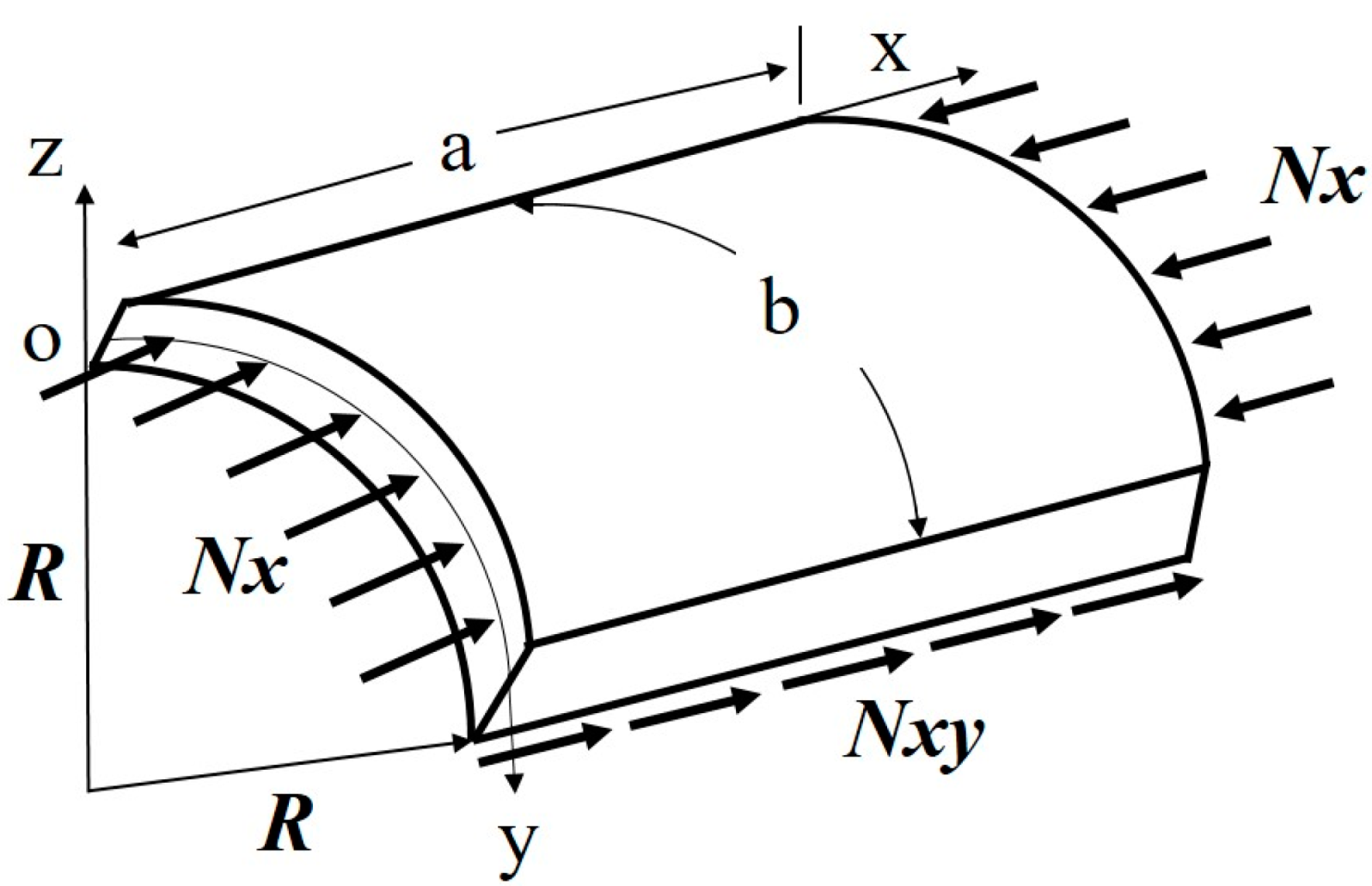
The bracket’s structure, made from cylindrically curved composite, was designed. Figure 1 shows a model of the curved composite panel considering loading conditions. The length of the curved panel is a. The length of the mid-surface is b. The length of the radius is R. Nx is the uniaxial compressive load. Nxy is the shear load. The constitutive relation equation was calculated using the Kirchhoff hypothesis. The lamination and definition of the angle for the target structure was carried out by applying the constitutive relation equation. The constitutive equation of the thin curved panel was also applied [21].
The design of the panel was carried out based on the laminate theory presented above. It was designed on the basis of the yield strength of the material for the application load. The composite design method using classical laminate theory was applied to carry out the structural design. The initial design is defined under the assumption that the fabric laminated in the load direction bears all of the load. This was complemented with the use of the mixed design method, in which fabric laminated in different directions from the load direction also contributes to 10% of the strength, and fabric in the ±45° direction was mixed with fabric in the 0° direction in order to determine the final number of layers.
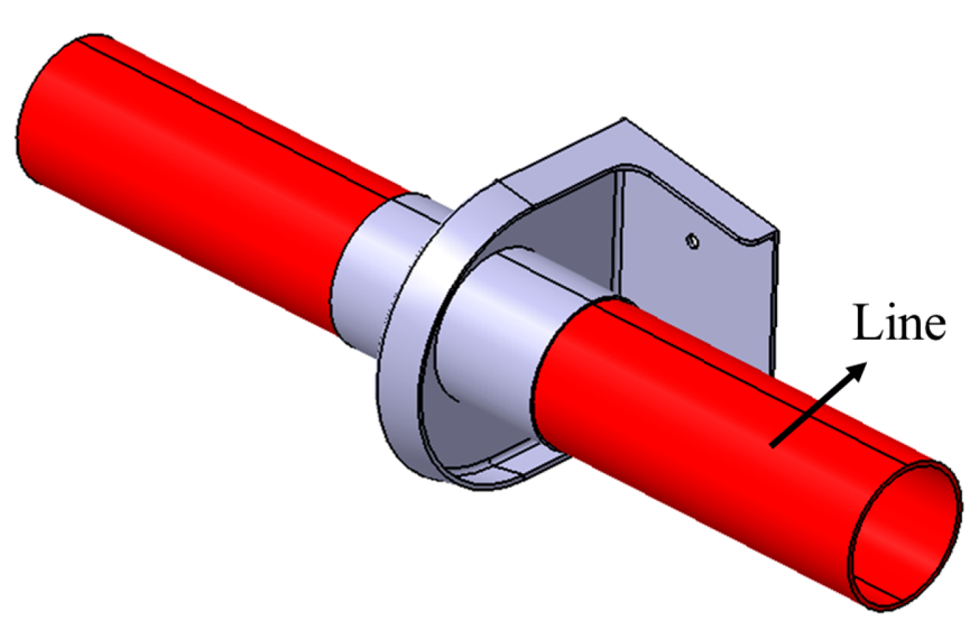
A total of six acceleration loads were applied to the designed structure and were set by analyzing the flight conditions of the target aircraft. The cases where a load of −6G and +3G in the z-axis direction and 2G in the y-axis direction are applied are considered the basic load. The ultimate load is the case where a load of 20G is applied in the x-, y-, and z-axes, respectively. And since a line was connected to the center of the bracket, a load of 700 g, which is the weight of the line, was applied. The load of the line was regarded as acting on the lower part of the inner cylinder. Figure 2 shows the configuration when applying the line. A margin of safety of 1.5 was applied to all respective loads. The load application condition is presented in Table 2.
Through the design of the structure according to the applied load, the design method, in which fabric in the ±45° direction was mixed with fabric in the 0° direction, was applied to determine the final number of layers. The thickness of the target structure was 1.1 mm, which was achieved by applying a total of five plies, since the thickness of one ply of prepreg is 0.22 mm. The ply angle was laminated as follows: [45°/0°/45°/0°/45°]. The optimized design of the stacking sequence for the bracket was determined. The final laminated angle was determined through the optimized design of the stacking sequence.
3. Structural Analysis
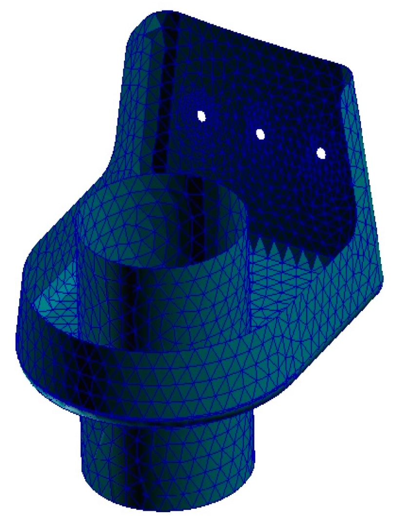
Finite element analysis was carried out on the bracket. The three-dimensional shape of the target structure was investigated to generate the finite element model. The result of the finite element modeling is shown in Figure 3. The total number of elements was 3148. A three-point triangle element was used. The structural shape is a combination of circles and panels. Therefore, it is reasonable to apply triangular elements for circular shapes and connection parts. The validity of the analysis results of the three-point triangle element was verified. The size of the element was optimized appropriately by increasing the number of elements, and the connecting part was applied as the fixed boundary condition, as shown in Figure 4. The axes are also shown in Figure 4. The x-axis is the direction in which the line is applied. The z-axis is the load direction of the line. For the load applied, the load of the lines combined with the inner cylinder structure and the acceleration condition was considered when performing the structural analysis. The load of the lines was applied as the distributed load to the respective elements. In the structural analysis, Nastran, a commercial numerical analysis software program, was used to perform structural integrity. For the structural integrity, linear static analysis was performed. Three analyses, namely, stress, deformation, and buckling analysis, were carried out. The stability under buckling load determines whether buckling occurs under the load when applied equally. Therefore, six loading conditions were applied equally to the designed bracket.
The loading condition 1 exerts −6G of acceleration in the z-axis direction, and following the structural analysis, the maximum stress was found to be a tension of 0.07 MPa and a compression of 0.054 MPa at layer 1, which is the outermost layer on the outside. Inside layer 2 had tension of 0.076 MPa and a compression of 0.045 MPa, and layer 5, which is the outermost layer on the inside, was found to have a tension of 0.069 MPa and a compression of 0.056 MPa. Therefore, it was confirmed to be a sufficiently safe structure. The displacement analysis result showed 0.155 mm of displacement to the side area, also confirming the structure as being safe enough. The safety margin for deformation was suggested to be within 5 mm considering structural interference in the design phase. Buckling analysis was also carried out, and the first load factor was 71. Therefore, the buckling analysis results also indicated that the structure was safe.
Loading condition 2 exerts +3G acceleration in the z-axis direction; however, it was confirmed that the result was similar to loading condition 1. In terms of the structural analysis results, the maximum stress was found to have a tension of 0.07 MPa and a compression of 0.054 MPa at layer 1, which is the outermost layer on the outside. Inside layer 2 had a tension of 0.076 MPa and a compression of 0.045 MPa, and layer 5, which is the outermost layer on the inside, was found to have tension of 0.069 MPa and a compression of 0.056 MPa. Therefore, the results indicate that the structure is safe. The deformation analysis revealed 0.155 mm of deformation in the side area. From the deformation analysis results, it was confirmed that it was a safe structure. Finally, buckling analysis was conducted. The analyzed load factor for the buckling analysis was 71. Therefore, the structure was found to be stable under buckling load conditions.
Loading condition 3 is the +2G case of acceleration in the y-axis direction. The maximum stress was found to have a tension of 0.117 MPa and a compression of 0.053 MPa at layer 1, which is the outermost layer on the outside. Inside layer 2 had a tension of 0.07 MPa and a compression of 0.078 MPa, and layer 5, which is the outermost layer of the inside, was found to have a tension of 0.122 MPa and a compression of 0.054 MPa, so it was confirmed as being safe enough. According to the displacement analysis, 0.348 mm of displacement was observed on the side. The buckling condition was also investigated, and the primary load factor for buckling was 71. Therefore, the structure was found to be stable.
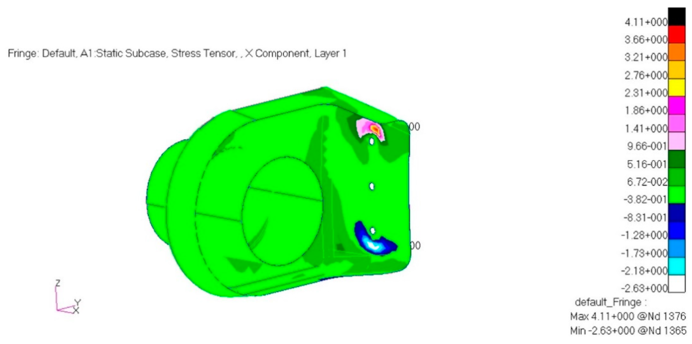
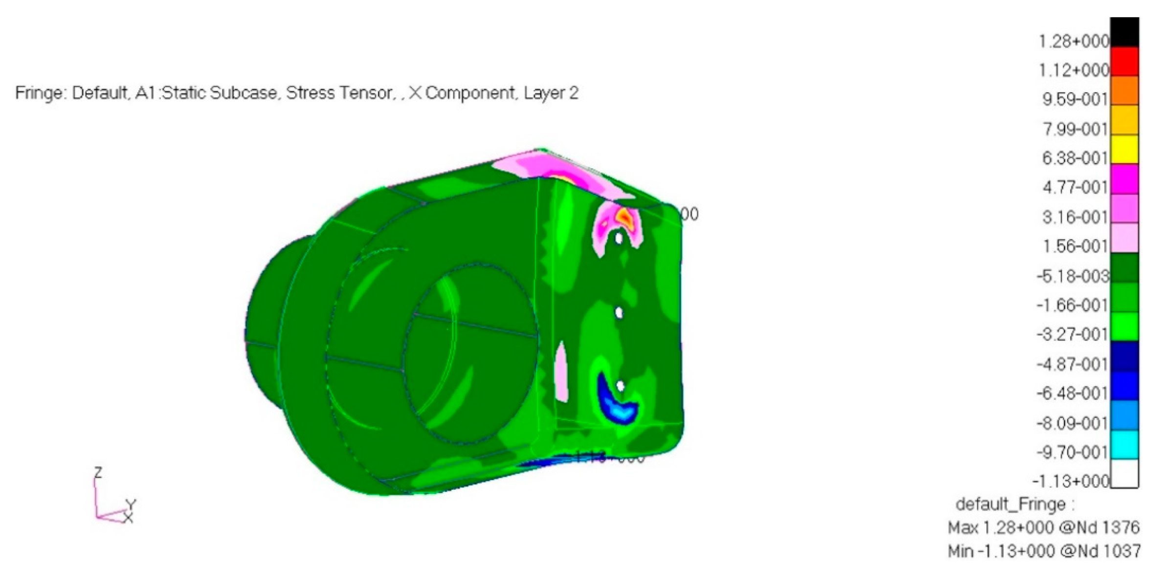
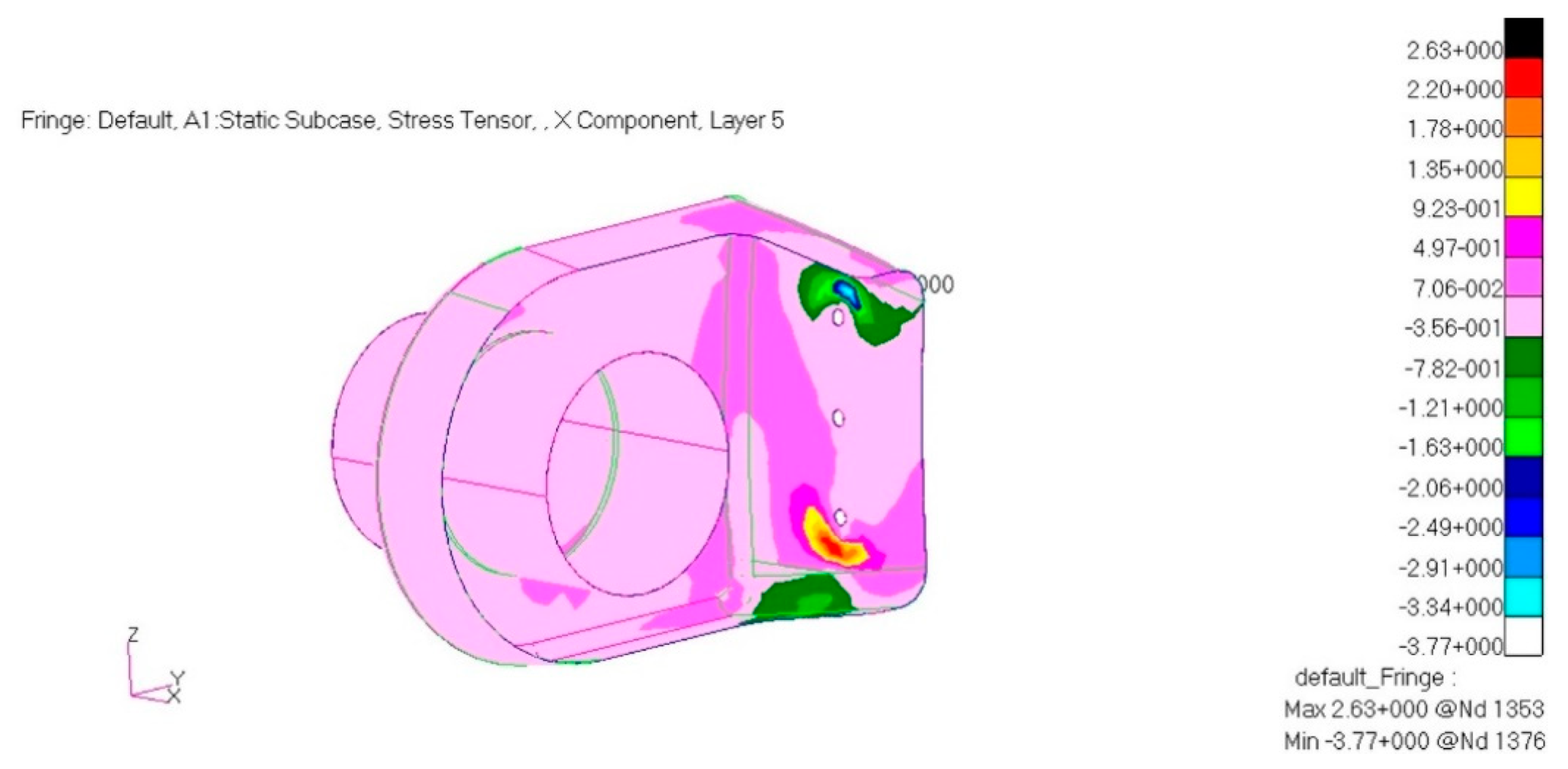
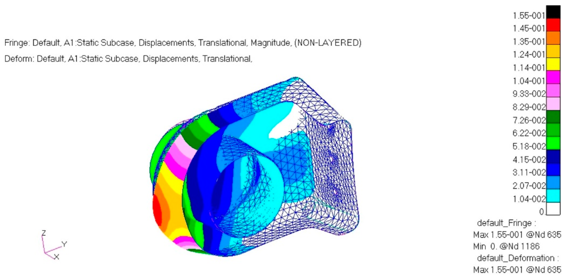
Loading condition 4 is the ultimate load, which applies a +20G acceleration condition in the x-axis direction. The tension stress is 4.11 MPa. The compressive stress is 2.63 MPa at layer 1 of the laminate. Inside layer 2 had a tension of 1.28 MPa and a compression of 1.13 MPa, and layer 5, which is the outermost layer on the inside, was found to have a tension of 2.63 MPa and a compression of 3.77 MPa. Therefore, the safety of the structure was confirmed. The displacement, using numerical analysis, was found to be 0.155 mm on the side area, indicating that the structure was safe. The buckling of the structure was analyzed. The first buckling loading factor was 14. The structure was found to be stable under these loading conditions.
Loading condition 5 also exerted +20G acceleration in the y-axis direction as the ultimate load, which was found to have a similar result as loading condition 3. The analysis was carried out and the maximum criterion of stress was found to be a tension of 0.117 MPa and a compression of 0.053 MPa at layer 1, which is the outermost layer on the outside. Inside layer 2 had a tension of 0.07 MPa and a compression of 0.078 MPa, and layer 5, which is the outermost layer on the inside, was found to have a tension of 0.122 MPa and a compression of 0.054 MPa. The structural integrity was found to be safe. The deformation analysis indicated 0.348 mm of deformation at the side part. Buckling load analysis was performed. The load factor for buckling was 14. Therefore, the structure was found to be stable.
Loading condition 6 exerts +20G acceleration in the z-axis direction. The maximum stress was found to be a tension of 0.07 MPa and a compression of 0.054 MPa at layer 1, which is the outermost layer on the outside. Inside layer 2 had a tension of 0.076 MPa and a compression of 0.045 MPa, and layer 5, which is the outermost layer on the inside, was found to have a tension of 0.069 MPa and a compression of 0.056 MPa. The designed structure was safe. The deformation analysis showed 0.155 mm deformation at the side. The deformation analysis results are valid. The first load factor for buckling was 14. Therefore, the structure is stable.
For isotropic materials, the von Mises yield theory using the strain energy of materials based on failures is applied, but it cannot be applied correctly to composite materials. Therefore, failure theory, which examines the failures of orthotropic materials based on the von Mises yield theory and is known as Tsai–Hill theory, was applied to examine the margin of safety.
Tsai–Hill theory is simplified under the assumption that tensile strength is identical to compressive strength, where, X, Y, and Z are the tensile strength of materials, and S is the shear strength. The margin of safety calculated through this theory is presented in Table 3. A summary of the deformation analysis and buckling load factor results is also provided in Table 3. As a result of analyzing six load definition cases, the design can be said to be safe and stable. The structural analysis result of typical load case 4 is presented in Figure 5, Figure 6, Figure 7 and Figure 8. The margin of safety was calculated based on a compressive strength of 708 MPa. The buckling analysis result is shown in Figure 9, which shows the load factor and displacement from the buckling. A buckling load factor of 14.43 means that the structure is 14.43 times more stable. The shape became deformed within 1 mm of displacement.
4. Design Modification
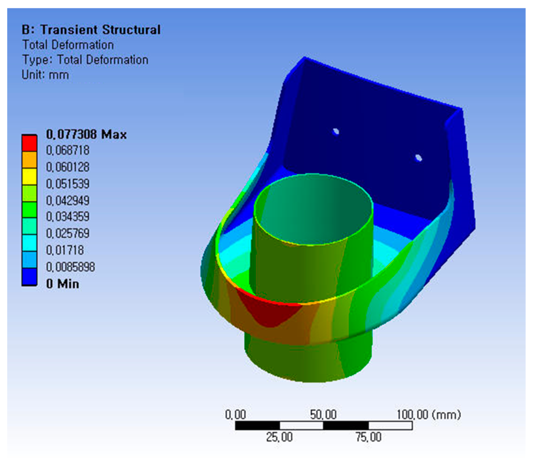
Composite materials were used in the design of a bracket for supporting structures within aircraft engines. The findings revealed that the use of composites was perhaps an excessive step, as the bracket is not a principal support structure, but rather a component inside the engine, so it was safe enough at the corresponding acceleration. Therefore, it was replaced with metallic material, AL 7075-T651, which was utilized to improve the design. A comparative analysis was conducted between the composite material and the metal material. In terms of the manufacturing cost, composite material manufacturing is expensive. Therefore, it was decided that the final structure would be made of aluminum. The thickness was the same as in the preceding design, at 1.1 mm. For the +20G acceleration condition in the x-axis direction, which is the ultimate state, the stress contour was found to be 21.672 MPa at the side. Therefore, the designed structure was safe. The deformation analysis result was found to be 0.077 mm. In terms of the deformation analysis result, it was suggested during the design phase that it would be safe enough if it fell within 5 mm considering structural interference. Figure 10 shows the stress analysis result and Figure 11 illustrates the deformation analysis result. Table 4 shows a comparison of the margin of safety between the structural analysis result when using composites and the result when using aluminum alloy. The margin of safety was calculated based on the longitudinal compressive strength and the maximum compressive strength. The margin of safety was calculated using Equation (2).
5. Conclusions
In this study, composites were used in the design of brackets to support structures inside an aircraft engine. The bracket has an important line passing through its central part. The safety of the bracket should be ensured during its operation and it should be protected. Therefore, the flight requirements were used in an analysis to determine the pattern of composites and to design the component. Numerical analysis was performed to assess the final design. FEA using Nastran and ANSYS software was used to investigate the structural integrity. Acceleration conditions, including extreme conditions, were considered in the load for the design and analysis, and the margin of safety was set at a value of 1.5. In the final design, the composite material was replaced with aluminum alloy, as it was decided that the composite design was excessive.
Author Contributions
H.P.: writing—review and editing and work guidance. All authors have read and agreed to the published version of the manuscript.
Funding
This work was supported by a Korea Institute of Energy Technology Evaluation and Planning (KETEP) grant funded by the Korea Government (MOTIE) (20213030020120, Development of product quality and O&M technology to improve all-steps reliability of offshore wind turbine blades). This work was supported by Korea Institute of Energy Technology Evaluation and Planning (KETEP) grant funded by the Korea government(MOTIE)(20213030020380, Development of adhesive-type modular over 70m for overcoming onshore transportation limitation).
Institutional Review Board Statement
Not applicable.
Informed Consent Statement
Not applicable.
Data Availability Statement
The data presented in this study are available on reasonable request from the corresponding author.
Acknowledgments
The authors would like to thank Younggen Cho.
Conflicts of Interest
The authors declare no conflicts of interest.
Abbreviations
| A | in-plane stiffness matrices |
| B | out-of-plane stiffness matrices |
| D | coupling stiffness matrices |
| N | membrane forces |
| M | bending moment |
| ε0 | strain |
| κ | curvature |
| Q | elastic constants |
References
- Albazzan, M.A.; Harik, R.; Tatting, B.F.; Gürda, Z. Efficient design optimization of nonconventional laminated composites using lamination parameters: A state of the art. Compos. Struct. 2019, 209, 362–374. [Google Scholar] [CrossRef]
- Megaheda, M.; Abobakrb, R.M.; Mohamed, S.A. Optimization of hybrid natural laminated composite beams for a minimum weight and cost design. Compos. Struct. 2020, 239, 111984. [Google Scholar] [CrossRef]
- Serhat, G.; Basdogan, I. Multi-objective optimization of composite plates using lamination parameters. Mater. Des. 2019, 180, 107904. [Google Scholar] [CrossRef]
- Kamaloo, A.; Jabbari, M.; Tooski, M.M.; Javadi, M. Optimization of thickness and delamination growth in composite laminates under multi-axial fatigue loading using NSGA-II. Compos. Part B 2019, 174, 106936. [Google Scholar] [CrossRef]
- Wencheng, L. Principles for determining material allowable and design allowable values of composite aircraft structures. Procedia Eng. 2011, 17, 279–285. [Google Scholar] [CrossRef]
- Shroff, S.; Acar, E.; Kassapoglou, C. Design, analysis, fabrication, and testing of composite grid-stiffened panels for aircraft structures. Thin-Walled Struct. 2017, 119, 235–246. [Google Scholar] [CrossRef]
- Zhongyi, M.; Sanshan, Z.; Younus, M.A. Saleem. Research on knowledge-based system for typical aircraft composite component design. Procedia Eng. 2011, 15, 1431–1435. [Google Scholar] [CrossRef]
- Komarov, V.A.; Kishov, E.A.; Kurkin, E.I.; Charkviani, R.V. Aircraft composite spoiler fitting design using the variable density model. Procedia Eng. 2015, 65, 99–106. [Google Scholar] [CrossRef]
- Marin, J.C.; Graciani, E. Normal stress flow evaluation in composite aircraft wing sections by strength of material models. Compos. Struct. 2022, 282, 115088. [Google Scholar] [CrossRef]
- Yang, Y.; Kim, M.; Lee, S. Optimal manufacturing of composite wing ribs in solar-powered UAVs: A study. J. Aerosp. Syst. Eng. 2016, 10, 50–58. [Google Scholar] [CrossRef]
- Kim, S.; Park, S.; Kim, T. Study for determining design allowable values of light weight composite unmanned aircraft structures. J. Aerosp. Syst. Eng. 2017, 11, 1–7. [Google Scholar]
- Kim, J.; Roh, K.; Lee, S. A study on bending behaviors of laminated composites using 2D strain-based failure theory. J. Aerosp. Syst. Eng. 2017, 11, 13–19. [Google Scholar]
- Kong, C.; Park, H.; Lee, K.; Shin, S. Investigation on strength recovery after repairing impact damaged aircraft composite laminate. J. Aerosp. Syst. Eng. 2010, 9, 862–868. [Google Scholar] [CrossRef]
- Jing, Z.; Sun, Q.; Liang, K.; Zhang, Y. Design of curved composite panels for maximum buckling load using sequential permutation search algorithm. Structures 2021, 34, 4169–4192. [Google Scholar] [CrossRef]
- Gebhardt, J.; Schlamp, M.; Ehrlich, I.; Hiermaier, S. Low-velocity impact behavior of elliptic curved composite structures. Int. J. Impact Eng. 2023, 180, 104663. [Google Scholar] [CrossRef]
- Duan, J.; Liu, Y.; Gao, Y.; Xu, B. Nonlinear static/dynamic behaviors of composite curved panels with piezoelectric patches in supersonic airflow. Compos. Struct. 2023, 319, 117138. [Google Scholar] [CrossRef]
- Bao, Q.; Yang, Z.; Lu, Z. An improved pull-out model for the composites with curved reinforcement. Int. J. Mech. Sci. 2024, 262, 108733. [Google Scholar] [CrossRef]
- Ahmadi, A.; Abedi, M. Transient response of delaminated composite curved beams subjected to a moving force. Structures 2023, 56, 104960. [Google Scholar] [CrossRef]
- Seifoori, S.; Parrany, A.M.; Mirzarahmani, S. Impact damage detection in CFRP and GFRP curved composite laminates subjected to low-velocity impacts. Compos. Struct. 2021, 261, 113278. [Google Scholar] [CrossRef]
- Choi, H.; Park, H. A study on the structural design and analysis of air intake of unmanned aerial vehicles applied to composite materials. J. Aerosp. Syst. Eng. 2022, 16, 81–85. [Google Scholar]
- Jones, R.M. Mechanics of Materials, 2nd ed.; Taylor & Francis, Inc.: Philadelphia, PA, USA, 1999; pp. 154–196. [Google Scholar]
Figure 1.
Model of the curved composite panel considering loading conditions.

Figure 2.
Configuration when applying the line.

Figure 3.
FEM modeling for structural analysis.

Figure 4.
Boundary condition and applied load for structural analysis. (a) Boundary condition: fixed support of joint part. (b) Distributed load on half of the cylinder structure.
Figure 4.
Boundary condition and applied load for structural analysis. (a) Boundary condition: fixed support of joint part. (b) Distributed load on half of the cylinder structure.

Figure 5.
Stress contour of layer 1.

Figure 6.
Stress contour of layer 2.

Figure 7.
Stress contour of layer 5.

Figure 8.
Deformed shape of structure.

Figure 9.
Buckling load factor.

Figure 10.
Stress analysis result applied to AL alloy.

Figure 11.
Deformation analysis result applied to AL alloy.


Table 1.
Properties of carbon fabric and epoxy resin prepreg [20].
Table 1.
Properties of carbon fabric and epoxy resin prepreg [20].
| Carbon/Epoxy Fabric Prepreg | Value |
|---|---|
| Longitudinal modulus [GPa] | 56.27 |
| Transverse modulus [GPa] | 54.86 |
| Shear modulus [GPa] | 4.21 |
| Longitudinal tensile strength [MPa] | 917.59 |
| Longitudinal compressive strength [MPa] | 708.86 |
| Transverse tensile strength [MPa] | 775.38 |
| Transverse compressive strength [MPa] | 702.97 |
| Shear strength | 132.57 |
| Ply thickness [mm] | 0.22 |
| Poisson’s ratio | 0.085 |
Table 2.
Load cases for structural design.
| Load Cases | Acceleration | Weight |
|---|---|---|
| Case 1 | −6G z axis | 700 g |
| Case 2 | +3G z axis | |
| Case 3 | +2G y axis | |
| Case 4 | +20G x axis | |
| Case 5 | +20G y axis | |
| Case 6 | +20G z axis |
Table 3.
Summary of compressive stress analysis results.
| Load Cases | Tsai–Hill Failure Criterion | Displacement |
|---|---|---|
| Load case 1 | 2.8 × 10⁻⁷ | 0.155 mm |
| Load case 2 | 2.8 × 10⁻⁷ | 0.155 mm |
| Load case 3 | 7.9 × 10⁻⁷ | 0.348 mm |
| Load case 4 | 9.7 × 10⁻⁷ | 0.155 mm |
| Load case 5 | 7.9 × 10⁻⁷ | 0.348 mm |
| Load case 6 | 2.8 × 10⁻⁷ | 0.155 mm |
Table 4.
Comparison between aluminum alloy and composite design results.
| Load Cases | Margin of Safety (Composite) | Margin of Safety (AL7075-T651) |
|---|---|---|
| Load case 1 | 12,641 | 785 |
| Load case 2 | 12,641 | 1141 |
| Load case 3 | 13,110 | 5511 |
| Load case 4 | 186 | 19 |
| Load case 5 | 13,110 | 241 |
| Load case 6 | 12,641 | 92 |
Disclaimer/Publisher’s Note: The statements, opinions and data contained in all publications are solely those of the individual author(s) and contributor(s) and not of MDPI and/or the editor(s). MDPI and/or the editor(s) disclaim responsibility for any injury to people or property resulting from any ideas, methods, instructions or products referred to in the content. |
© 2024 by the author. Licensee MDPI, Basel, Switzerland. This article is an open access article distributed under the terms and conditions of the Creative Commons Attribution (CC BY) license (https://creativecommons.org/licenses/by/4.0/).
Share and Cite
MDPI and ACS Style
Park, H. Design and Analysis of a Curved Composite Bracket. Appl. Sci. 2024, 14, 3739. https://0-doi-org.brum.beds.ac.uk/10.3390/app14093739
AMA Style
Park H. Design and Analysis of a Curved Composite Bracket. Applied Sciences. 2024; 14(9):3739. https://0-doi-org.brum.beds.ac.uk/10.3390/app14093739
Chicago/Turabian StylePark, Hyunbum. 2024. "Design and Analysis of a Curved Composite Bracket" Applied Sciences 14, no. 9: 3739. https://0-doi-org.brum.beds.ac.uk/10.3390/app14093739
Note that from the first issue of 2016, this journal uses article numbers instead of page numbers. See further details here.