
Tribological Performance Study of Low-Friction PEEK Composites under Different Lubrication Conditions

Marine Engineering College, Dalian Maritime University, Dalian 116000, China
*
Author to whom correspondence should be addressed.
Appl. Sci. 2024, 14(9), 3723; https://0-doi-org.brum.beds.ac.uk/10.3390/app14093723
Submission received: 5 March 2024
/
Revised: 21 April 2024
/
Accepted: 25 April 2024
/
Published: 27 April 2024
(This article belongs to the Special Issue Advanced Composites and Hybrid Materials)
Abstract
:This study introduces a low-friction composite based on PEEK to improve its friction and wear properties. The composite incorporates PTFE as a solid lubricant and utilizes PPTA as a reinforcing material within the PEEK matrix. These components were prepared utilizing a compression molding method, followed by a series of exploratory experiments to identify the optimal preparation conditions for PEEK. This research assesses how the PTFE/PPTA/PEEK composites perform in terms of friction and wear under dry and oil-lubricated conditions. By examining wear tracks using scanning electron microscopy and white light interference microscopy, this study aims to uncover the wear mechanisms of PEEK and its composites under different lubrication scenarios. Results show that the main wear mechanisms for the PTFE/PPTA/PEEK composites and bearing steel are ploughing and adhesive wear. The presence of PPTA helps reduce wear by leveraging its strong fibers and thermal stability, while the coefficient of friction decreases as PTFE creates a smooth, solid lubricating film on the surface. Notably, PEEK composites containing 25 wt% PTFE and 6 wt% PPTA demonstrate the lowest wear rates and reduced coefficient of friction in both dry and oil-lubricated conditions.
1. Introduction
Sliding bearings are preferred due to their ability to offer low coefficients of friction (COF) and high load capacities, making them indispensable in marine machinery and equipment [1]. Nonetheless, the lubricant oil could be compromised under conditions of high temperatures, heavy loads, or other challenging operational conditions. Therefore, this can lead to a degradation in the lubrication state in sliding bearings; the transition occurred from a pristine condition to mixed and boundary lubrication states [2]. In situations where there is no lubricating medium, traditional bearing materials like Babbitt metal experience considerable wear. Replacing Babbitt metal with a self-lubricating polymer material such as poly-ether-ether-ketone (PEEK) could greatly enhance the wear resistance of bearings when facing dry friction and inadequate lubrication [3,4]. PEEK is excellent for its self-lubricating capabilities, resistance to chemicals, and robust mechanical properties, making it a material of choice in various engineering applications, including bearing components [5,6]. However, the wear resistance of PEEK is challenged by its susceptibility to severe adhesive wear under the influence of frictional heat, emphasizing the necessity to bolster its tribological performance [7].
The integration of solid lubricants, specifically graphite (GP) and polytetrafluoroethylene (PTFE), into PEEK has been explored for its potential to enhance both the mechanical integrity and tribological performance of the base material. Research conducted by Pang et al. [8] on GP-modified polyether ether ketone (GP/PEEK) composites revealed that the inclusion of 15 wt% GP into PEEK led to a notable 59.5% decrease in the coefficient of friction (COF) compared to pure PEEK. However, this modification may lead to a compromise in wear resistance properties. Further study by Bahadur et al. [9] into PEEK/PTFE composites interacting with steel discs under conditions of sliding contact demonstrated that the formation of a lubricating film on the steel discs could notably improve wear resistance. Voort et al. [10] suggested that the addition of PTFE to PEEK resulted in the formation of a lubricant film by the composite material during sliding friction, which adhered to the contact surface to shield it from wear. Yang et al. [11] suggested that PTFE could form a molecularly oriented lubricant film on the friction-engaged surface, reducing friction and improving wear resistance. Thus, the selection of PTFE as a solid lubricant was seen as a strategic method to enhance the tribological properties of PEEK composites.
Moreover, reinforcing polymer composites with fibers has been demonstrated as an effective method to enhance their strength. The friction and wear characteristics of fiber-reinforced polymer composites are intricately linked to the properties of the fibers. Poly-p-phenylene-terephthalamide (PPTA) stands out as a fiber with exceptional qualities such as robust tensile strength, high modulus, resistance to heat, and commendable mechanical properties [12]. Research by Chen et al. [13] demonstrated that adding 7 wt% aramid fibers into epoxy resin notably elevates the material’s tensile and impact strength, thermal stability, and damping capabilities. Further analysis by Çetkin et al. [14] of the tribological characteristics of composites composed of aramid-fiber-filled glass fiber fabric under dry friction conditions revealed that the coefficient of friction decreased as the aramid fibers made adequate contact with the frictional surface. The incorporation of 1.5 wt% aramid fibers into the glass fiber fabric significantly reduced surface deformation of the composites, leading to a 65% improvement in wear resistance properties. Yu et al. [15] previously investigated the friction and wear properties of self-lubricating fabrics consisting of cyclic aramid and PTFE fibers under elevated temperatures, revealing that PTFE composites reinforced with cyclic aramid fibers displayed remarkable resistance to plastic deformation at high temperatures. The durability of these self-lubricating fabric composites against wear at high temperatures is related to their mechanical properties under such conditions. To further the resistance of PEEK against adhesive wear, the inclusion of PPTA into PEEK is planned to improve its properties.
The study of friction and wear performance of PEEK indicates that these properties are significantly influenced by the conditions under which the material is prepared. Researchers have varied their approaches toward PEEK [16,17,18,19]; different temperatures and pressures were utilized during the preparation stage to assess the mechanical properties of PEEK composites. Hu et al. [20] fabricated CFF/PEEK composites using varying molding temperatures and pressures. The results indicated that inadequate sintering temperatures hinder proper fiber impregnation in PEEK, whereas too high temperatures may cause PEEK to degrade, leading to brittleness and cracking. Similarly, insufficient forming pressure weakened the bond between PEEK and the fibers, while excessive pressure could lead to the extrusion of PEEK from the composite matrix. These findings emphasize the balance required in maintaining appropriate sintering temperatures and pressures to avoid adverse impact on the material’s mechanical characteristics.
Building on the above understanding, this study introduced a novel low-friction PEEK-based composite, utilizing PEEK as the base matrix, supported by PTFE as the solid lubricant and PPTA as the strengthening component. Thereafter, the investigation examined how different sintering temperatures and forming pressures influenced the tribological behavior of PEEK. In addition, we investigated how the inclusion of PTFE and PPTA impacted the tribological properties of PEEK under conditions of both dry friction and oil lubrication. Finally, the wear mechanisms of PEEK and its composites were examined.
2. Materials and Methods
2.1. Preparation of Materials and Samples
For the purposes of this study, the materials selected were commercially sourced PEEK, PPTA, and PTFE. PEEK was procured from Victrex, Lancashire, UK, characterized by an average particle size of 48 μm and a density of 1.35 × 10⁻³ kg/m3; PTFE obtained from DuPont in Wilmington, DE, USA, featured an average particle size of 150 μm and a density of 1.38 × 10⁻³ kg/m3. Finally, PPTA was sourced from Teijin in Osaka, Japan, with specifications including an average particle size of 50 μm and a density of 2.16 × 10⁻³ kg/m3. The components of PEEK-based composites are shown in Table 1.
In the process of preparing samples of PEEK and PEEK composites, a method involving compression molding was employed. First, the raw material was fully dried in an electric thermostatic drying oven and stirred with an oscillator for 10 min to mix evenly. Thereafter, the blended powder mixture was processed into preforms using an electric tablet press. These preforms were then carefully placed in a sintering mold, previously treated with a release agent, and subjected to heat. The final step involved optimizing the samples through die-grinding, machine polishing, and ultrasonic cleaning to obtain a usable test sample (15.7 × 10 × 6.3 mm). An important aspect of this procedure is the application of pressure in phases. First, the pressure is applied at half of the designated level and sustained for 10 min to guarantee overall stability. This is followed by increasing the pressure to the intended final level and maintaining it for another 10 min to complete the compression. Then, a gradual heating method is employed, beginning with preheating to 200 °C and maintaining this temperature for 30 min to ensure thorough mold filling before reaching the final temperature (350 °C, 360 °C, 370 °C, 380 °C, 390 °C) and maintaining it for another 30 min, and finally allowing the sample to cool in the furnace. This preparation process is depicted in Figure 1.
2.2. Methods
A digital Type D Durometer (LXD-D Shore hardness tester, made in Wenzhou, China) was used to assess the shore D hardness (HD) of the samples, adhering to the GB/T 2411-2008 [21] standards. This process includes placing the polished sample on the testing platform, gently positioning the pressure probe of the hardness tester about 9 mm from the edge of the specimen, and noting the hardness value after both surfaces have reached a stable state. The final hardness value is determined by averaging five measurements taken from various locations.
The density testing method adheres to the GB/T 1033.1-2008 [22] guidelines, considering PEEK composites as impermeable solid plastics following fine grinding and polishing. The impregnation method is utilized to determine their density, with the density of PEEK composites being calculated utilizing the specified Equation (1):
where ρs is density (kg/m3), m1 is the mass of the sample in air (kg), m2 is the mass of the sample in the impregnating solution (kg), and ρw is the density of distilled water at 25 °C.
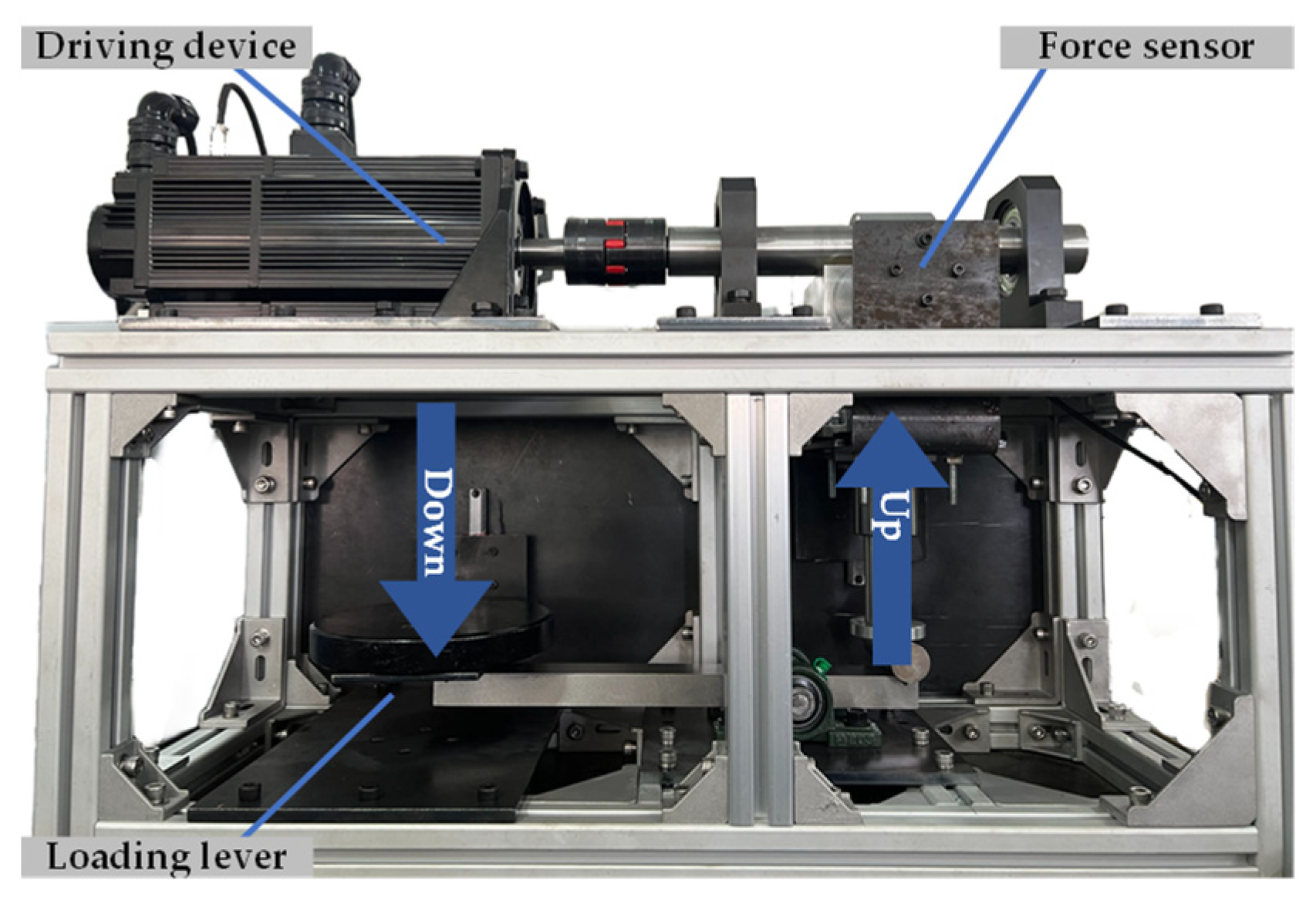
The test method of tribological properties adheres to the standards set forth in GB/T 3960-2016 [23]. This process involves the use of a self-made shaft-block tribological tester (Figure 2) to determine the most effective preparation conditions for PEEK. In this setup, the friction pair consists of PEEK and a 45-steel shaft, with the latter having an outer diameter of 70 mm. The experiment is conducted under a load of 450 N and a linear velocity of 0.4 m/s over a duration of 2 h. Both components in the friction pair have a surface roughness of 0.35 to 0.4 μm, and the testing environment involves dry friction. The average wear rate is derived through the application of Equation (2).
where W is the volume wear rate (mm3/(N·m)), m3 is the mass before wear (g), m4 is the mass after wear (g), ρ is the sample density (g/mm3), F is the normal load (N), and Ls is the total sliding distance (m).
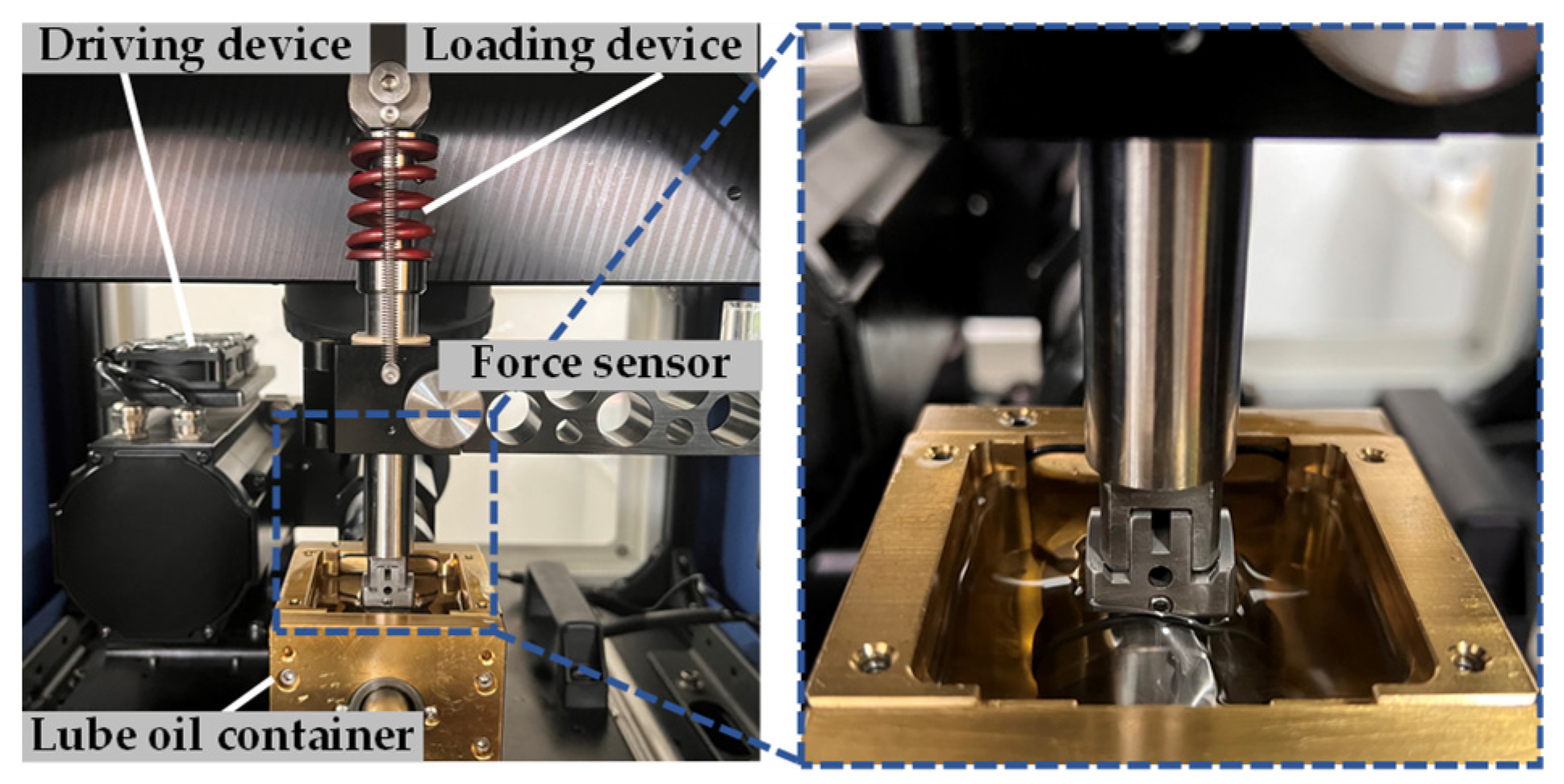
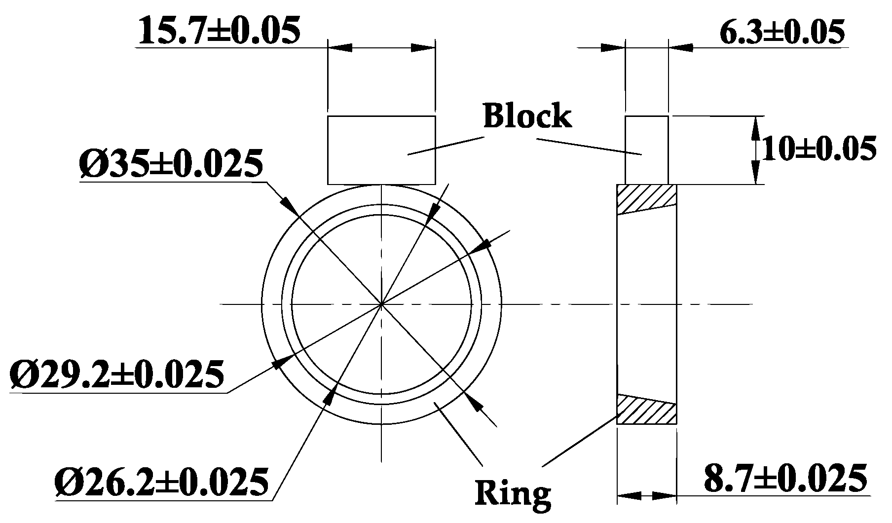
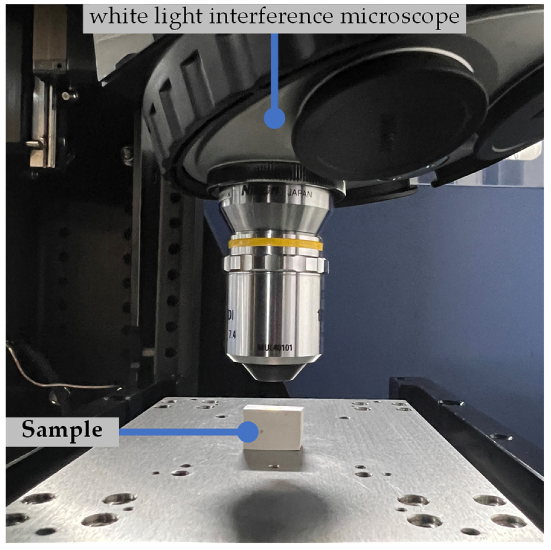
Further study into PEEK composites, which include PTFE and PPTA, was carried out utilizing the MTF-5000 Multi-function tribometer (RTEC, San Jose, CA, USA) (Figure 3). The experimental setup involved a TIMKEN A4138 (Timken, Saint Louis, MO, USA) bearing as the test ring (Figure 4), which has an outer diameter of 35 mm. During this testing phase, the conditions entail applying a 150 N load, maintaining a linear velocity of 0.4 m/s, and conducting the test for a total duration of 2 h. The surface roughness of the friction pair was adjusted to 0.35 to 0.4 μm through machining, with experiments conducted under both dry friction and oil lubrication conditions. The lubricant utilized in this context is SpectraSyn 4 [24]. Post-tribological testing, the depth of wear was quantified utilizing a white light interference microscope (WLI, MFT-5000 from RTEC, San Jose, CA, USA, Figure 5), and the detailed wear mark morphology was analyzed with a scanning electron microscope (SEM, VEGA3 from TESCAN, Brno, Czech Republic).
3. Results
3.1. Influence of Sintering Temperature on the Tribological Behavior of PEEK
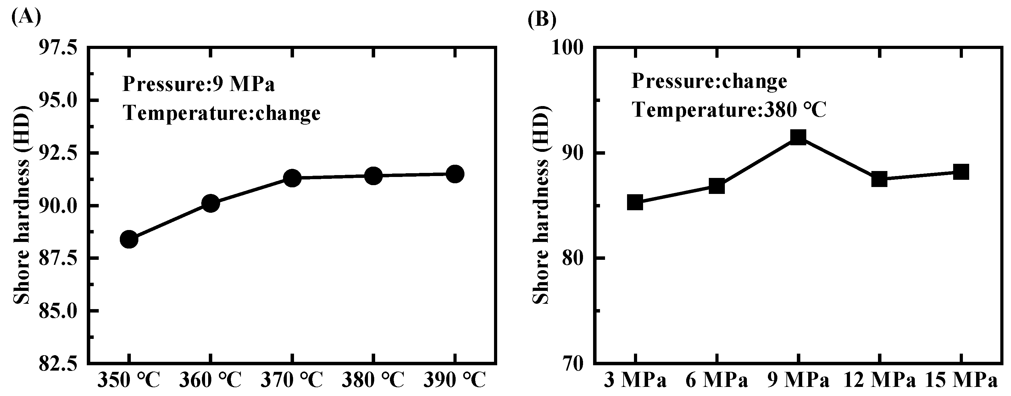
Figure 6A depicts the variation of Shore hardness in PEEK at five different sintering temperatures, complemented by an analysis of the impact these temperatures have on PEEK’s tribological attributes, as depicted in Figure 7A–C. Observations from Figure 6A indicate a gradual increase in PEEK’s matrix hardness with rising sintering temperatures, resulting in a plateau upon reaching 91 SHD. Figure 7B,C further explain this phenomenon, displaying a pattern of decline followed by a rise in both the average COF and wear rate of PEEK, determining that the most effective sintering temperature is 380 °C for reducing both COF and wear rate. Notably, when exposed to sintering temperatures ranging from 350 °C to 360 °C, the COF of PEEK rises during the initial wear-in phase and stays elevated during the steady wear period (Figure 7A). This is attributed to the fact that at sintering temperatures marginally above PEEK’s melting point, there is uneven heat distribution in the resistance furnace. Therefore, some particles fail to fully melt, leading to a coexistence of liquid and solid phases. This heterogeneity disrupts the uniformity of the PEEK matrix, negatively affecting its densification process in PEEK [25]. The resulting insufficient matrix hardness compromises the material’s ability to withstand the abrasive action of steel shafts, thereby elevating friction levels during the steady wear phase. A distinct pattern is noted when sintering temperatures are between 370 °C and 390 °C, showing a trend in the COF during the initial wear-in phase where it tends to first rise and then fall. Specifically, at a sintering temperature of 380 °C, the COF during the steady wear phase reduces, a change attributed to the more complete melting of PEEK powder. This results in a larger liquid phase and a tighter molecular arrangement [26], thereby enhancing the density and matrix hardness sufficient to resist external pressures effectively. However, increasing the sintering temperature to 390 °C leads to an uptick in PEEK wear, a result of increased brittleness and weakened tensile strength of the PEEK resin [27]. Hence, it is deduced that the optimal sintering temperature for achieving superior friction and wear characteristics in PEEK is 380 °C.
3.2. Impact of Molding Pressure on the Tribological Behavior of PEEK
Figure 6B illustrates the variation of Shore hardness in PEEK under five different forming pressures, alongside the impact these pressures have on the tribological attributes of PEEK, illustrated in Figure 7C,D. A notable pattern emerges where, with increasing forming pressures, the hardness of PEEK shows a pattern of initially increasing and then decreasing (Figure 6B), reaching its peak at 9MPa. At this peak pressure, we observe the minimum average COF (Figure 7E) and the lowest wear rate (Figure 7F). The underlying rationale is that a 9MPa forming pressure effectively narrows the gaps between PEEK molecules, allowing the molten PEEK to more thoroughly infiltrate the pores and consolidate the matrix. Conversely, elevating the pressure beyond 9 MPa to 15 MPa introduces elastic recovery post-unloading in the PEEK powder compressed samples, thereby reintroducing gaps in the material [28]. In addition, this high pressure restricts the mobility of PEEK molecules, complicating the diffusion of molten PEEK through the pores and leading to localized bonding flaws. This phenomenon gradually weakens the material overall strength [29]. Therefore, the data suggest that a 9 MPa forming pressure is optimal for fabricating PEEK materials through the compression molding method in a laboratory setting.
3.3. Influence of Incorporating PPTA on the Tribological Behavior of PEEK under Varying Lubrication Conditions
Figure 8A,B illustrates how varying proportions of PPTA impact the density and hardness of PPTA/PEEK composites. As detailed in Figure 8A, increasing the PPTA proportion in the matrix nudges the composite’s density closer to that of pure PEEK, albeit with a marginal reduction in hardness. This result is due to the similar density between PPTA and PEEK. When merged, these materials exhibit strong interfacial bonding and minimal porosity, leading to negligible density shifts. Additionally, the pliability of PPTA marginally diminishes the elasticity of the material, as indicated by substrate deformations observed during hardness testing. Therefore, an increase in PPTA proportion correlates with a slight decrease in substrate hardness (Figure 8B).
Figure 9A–C illustrates how varying proportions of PPTA affect the mechanical and tribological characteristics of PEEK under dry friction conditions. As illustrated in Figure 9, pure PEEK has a high friction coefficient amplitude; with a gradual increase in PPTA proportion, the friction coefficient amplitude of the composite decreases first and then increases. This is attributed to the melting of PEEK due to the heat generated through friction, which then deforms under the shear stress exerted by the steel ring. This frictional heat is continuously regenerated and accumulates, leading to repeated melting of PEEK and an increased COF. The addition of PPTA to the composite decreases the peak coefficient of friction of PEEK/PPTA composites during the initial wear-in phase, as PPTA retains its robust mechanical strength even at high temperatures. As the PPTA proportion rises from 2 wt% to 6 wt%, there is a progressive growth in the contact area between the fibers and the counter-face, highlighting the enhanced impact of the reinforcing material. Therefore, the peak coefficient of friction of the PPTA/PEEK composites gradually decreases during the wear-in phase. However, elevating the PPTA proportion from 6 wt% to 10 wt% leads to an incremental increase in the peak COF during the wear-in phase. This phenomenon occurs because an excessive amount of PPTA causes the fibers to bunch and aggregate, resulting in weakened bonding strength between the fibers and the matrix. In addition, the presence of loose fibers on the material’s surface can intensify friction and potentially lead to localized heat concentration and wear [30].
Figure 9D–F illustrates how varying proportions of PPTA influence the mechanical and tribological behavior of PEEK under conditions of oil lubrication. Figure 9 indicates that integrating an optimal amount of PPTA into PEEK significantly enhances its wear resistance properties. Specifically, increasing the PPTA proportion from 2 wt% to 6 wt% leads to a significant reduction in the average COF for the PPTA/PEEK composites. Additionally, there is a significant decrease in the severity of wear, evidencing an improvement in wear resistance. The wear depth of the 94 wt% PEEK/6 wt% PPTA composite was reduced by 44% compared to that of the PEEK-only samples. This enhancement can be attributed to the low friction experienced under oil-lubricated conditions and the strong tensile properties of PPTA [31], which resists shear damage effectively. As the PPTA proportion increases, the interaction surface between the fiber and bearing expands, offering enhanced load support. This minimizes the direct contact between PEEK and the steel shaft, decreasing the likelihood of adhesive wear. However, with the increase in PPTA proportion from 6 wt% to 10 wt%, a gradual rise in the coefficient of friction (COF) and an intensification of wear tracks are observed (Figure 9F), indicating a decline in wear resistance. This trend reflects the behavior observed under dry friction conditions, where excessive PPTA levels lead to fiber agglomeration, undermining overall anti-wear characteristics of the composite.
3.4. Impact of Incorporating PTFE on the Tribological Behavior of PEEK under Varying Lubrication Conditions
Figure 10A,B demonstrates how varying proportions of PTFE influence the density and hardness of PTFE/PEEK composites. Figure 10 demonstrates a progressive rise in the density of the composites with an increase in PTFE proportion, alongside a concurrent softening of the material. This phenomenon is explained by the higher density of PTFE compared to PEEK, without a corresponding increase in porosity in the material prepared utilizing standard procedures. Therefore, the incorporation of PTFE into PEEK results in denser composites. Moreover, due to the soft nature of PTFE, the hardness of the matrix decreases with an increase in the proportion of PTFE.
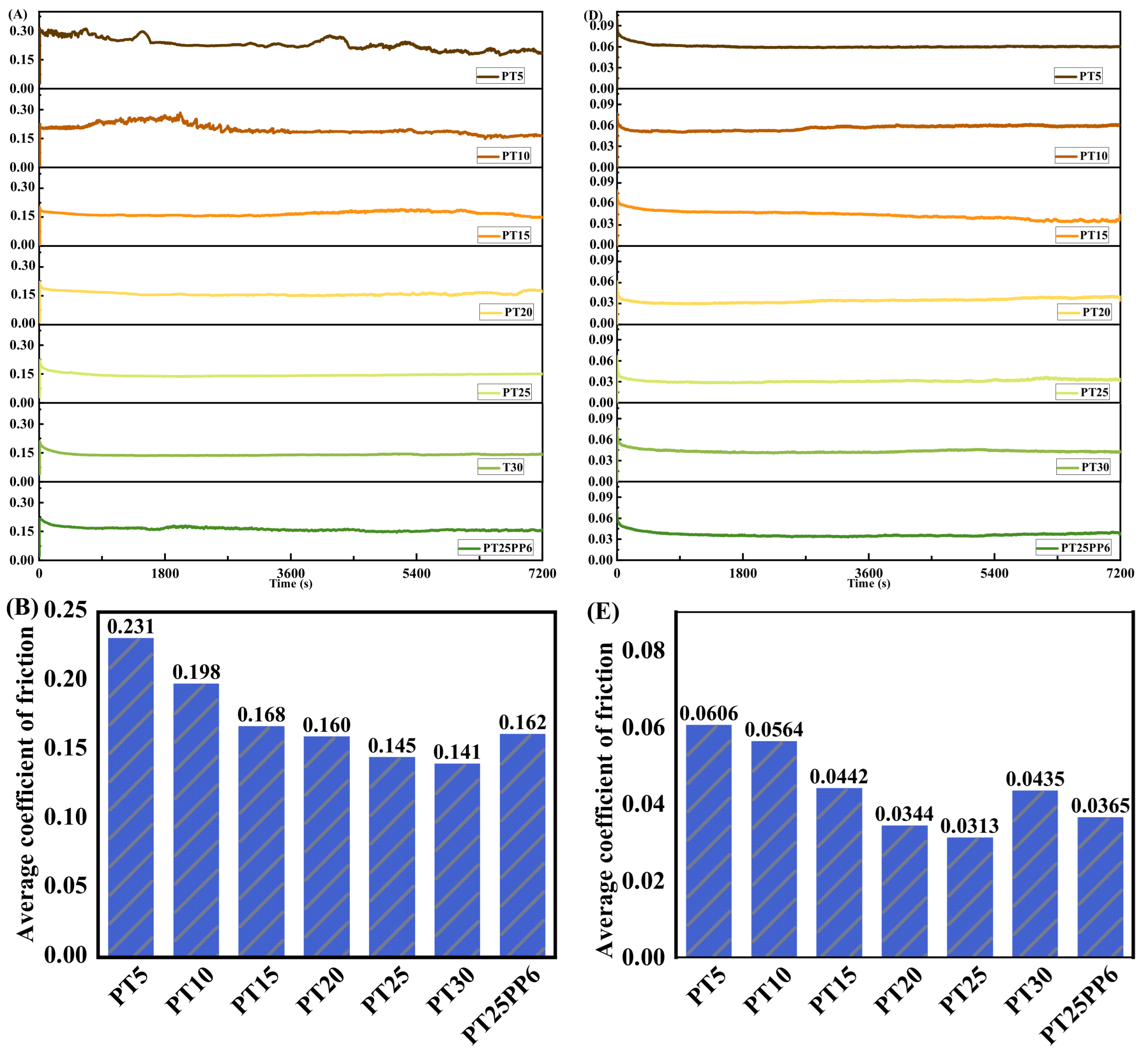
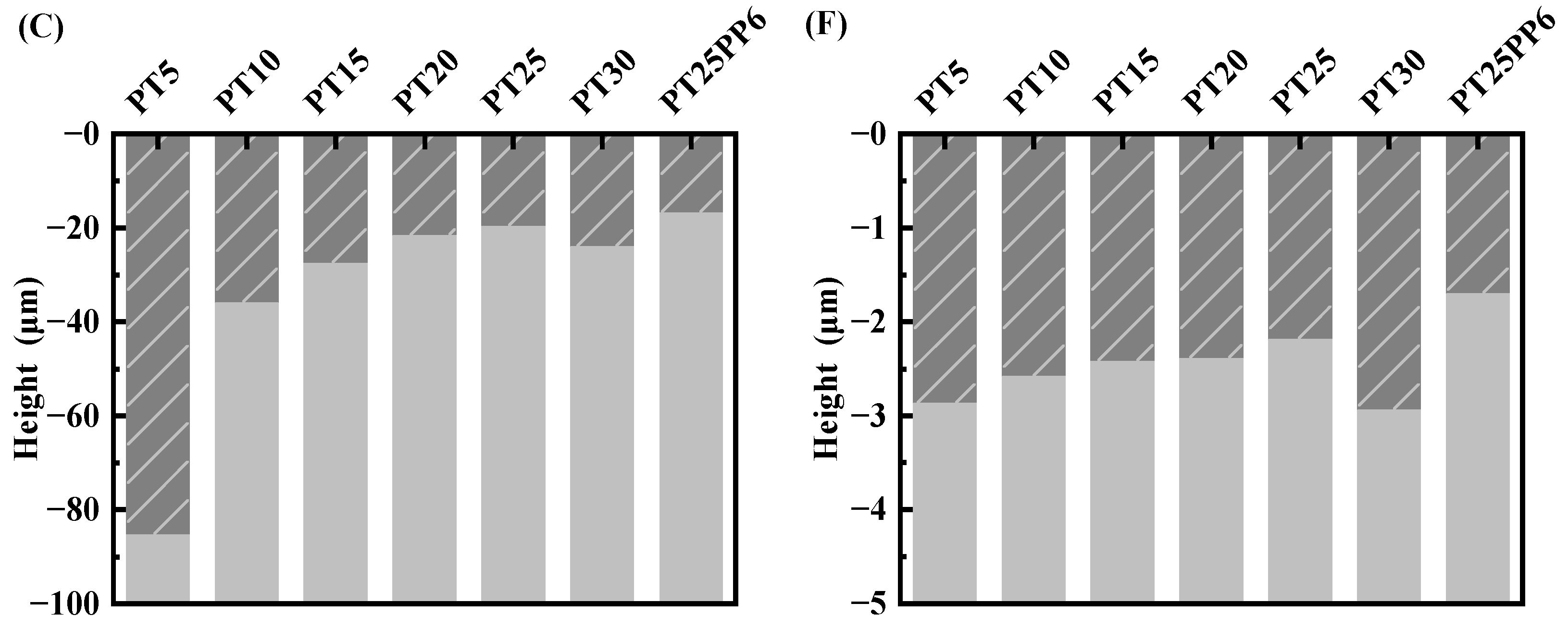
Figure 11A–C demonstrates how varying proportions of PTFE impact the tribological performance of PEEK under dry friction conditions. Figure 11 indicates that incorporating a suitable amount of PTFE into PEEK resin significantly lowers the COF of the composite material and enhances its wear resistance. With an increase in the PTFE content from 5 wt% to 25 wt% in the composites, the initial COF of the PTFE/PEEK composites stabilizes, the average COF decreases gradually, and there is a significant reduction in the wear depth. This is attributed to PTFE’s exceptionally low COF, making the composite matrix more pliable with added PTFE, which mitigates localized fractures due to the brittleness of PEEK. Therefore, this stabilization allows the frictional force to become more consistent. When subjected to pressure and shearing forces, the softer PTFE material spreads out during friction, forming a sleek lubricating film on the material’s surface. By enlarging the contact area between PTFE and the metal friction counterpart, this mechanism diminishes the COF. Nonetheless, composites containing 30 wt% PTFE display a lower COF compared to those with 25 wt% PTFE, albeit with an increase in wear depth. This phenomenon occurs because PTFE’s surface energy is extremely low, limiting its bonding strength with PEEK. Despite the very low COF of the PT30 composite, the lubricating film fails to consistently adhere to the material surface, leading to greater wear depth.
Under conditions of oil lubrication, the influence of varying PTFE proportions on the tribological performance of PEEK is depicted in Figure 11E,F. As presented in Figure 11, the incorporation of PTFE into PEEK effectively lowers the COF and provides a degree of wear resistance. Notably, the composite comprising 75 wt% PEEK and 25 wt% PTFE demonstrates the lowest COF and minimal wear depth among them. Nonetheless, under oil lubrication conditions, there is no substantial improvement in the wear resistance of PTFE/PEEK composites (Figure 11F). This lack of improvement is due to PTFE’s flexibility, which leads to a reduced load-bearing capacity in PTFE/PEEK composites as the PTFE proportion increases, resulting in substrate deformation.
In both dry friction and oil lubrication scenarios, the PT25PP6 composites displayed shallower wear marks than the composites composed of PT25 (Figure 11C,F). Nevertheless, the COF for the former was higher than that of the latter. This occurrence can be credited to the increased hardness of the composite material resulting from the addition of PPTA, leading to a superior load-bearing capacity and therefore reduced deformation of the composite material. The micro-convex features formed by PPTA take the place of PTFE in contact with the steel ring, and since PPTA inherently has a higher COF than PTFE, this results in an increased COF. Therefore, it can be inferred that composites containing 6 wt% PPTA, 25 wt% PTFE, and 69 wt% PEEK strike a harmonious equilibrium between a low COF and outstanding wear resistance characteristics.
3.5. Analysis of Microstructure and Wear Mechanisms
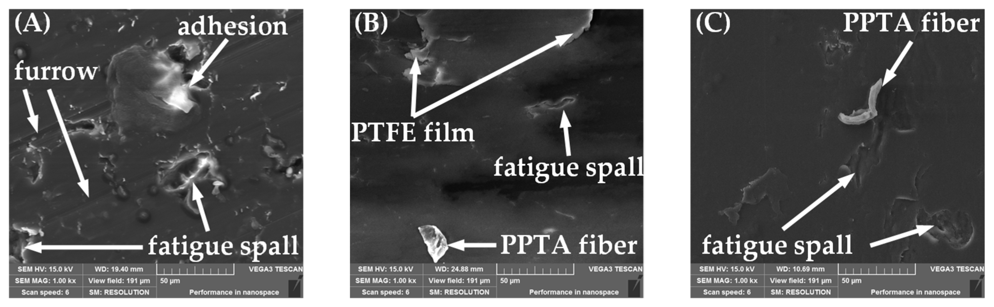
Figure 12 showcases the microscopic morphology of abrasion marks exhibited by PEEK and its composites under dry friction conditions. The wear surface of the pure PEEK sample exhibited adhesion, spalling, and grooves carved by the bearing asperities in the frictional direction (Figure 12A). In contrast, the surface of the PEEK composite sample, containing 6 wt% PPTA and 25 wt% PTFE, displayed a smoother appearance (Figure 12B). As the proportion of PPTA in the PPTA/PEEK composite rises, the quantity of micro-convex structures on the worn surface also increases (Figure 12C,D); by doing so, the contact area between the steel ring and PEEK is minimized, subsequently decreasing the likelihood of adhesive wear. Conversely, as the proportion of PTFE in the PTFE/PEEK composite increases, the size of the lubricating film on the surface of the wear marks expands (Figure 12E,F). This enhancement allows the steel ring to slide more smoothly over the surface, aided by the lubricating film, leading to a reduction in the COF of the composite material.
The microstructure of the wear patterns on PEEK and its composites, particularly when subjected to oil lubrication, indicates interesting insights. The analysis depicted in Figure 13 exhibits that both PEEK and its composite materials exhibit behaviors under oil lubrication reminiscent of dry sliding conditions. Notably, when pure PEEK samples are exposed to oil lubrication, they exhibit signs of grooves and localized spalling (Figure 13A). Conversely, a PEEK composite sample, fortified with 6 wt% PPTA and 25 wt% PTFE, shows significantly smoother worn surfaces (Figure 13B). This improvement is attributed to the lubricant medium’s role in facilitating heat dissipation generated through friction and significantly reducing surface adhesion on the pure PEEK samples. Further exploration into the effects of varying the composition indicates that increasing the PPTA proportion in PPTA/PEEK composites from 2% to 6% effectively mitigates the risk of adhesive wear, resulting in smoother wear surfaces (Figure 13C,D). Despite these improvements, PPTA/PEEK composites remain susceptible to the formation of grooves by the hard asperities of bearings (Figure 13E,F). An increase in PTFE proportion from 5 wt% to 25 wt% results in the filling of some grooves on the PTFE/PEEK composite’s worn surface by a flattened PTFE lubricating film, which expands in area proportional to the increase in PTFE proportion.
In summary, at elevated temperatures and with its high brittleness, PEEK typically exhibits abrasive and adhesive wear owing to its inadequate mechanical properties. The heat generated by friction can lead PEEK to melt, contributing to conditions for adhesion which, upon the sliding motion, results in the material spalling off. Incorporating PPTA into PEEK not only sustains the mechanical strength of the composite at elevated temperatures, but also diminishes the adhesion effect. The micro-convex shape of PPTA reduces the contact area between the composite and the steel ring while simultaneously enhancing the load-carrying capacity of the composite [32]. Additionally, under pressure, PTFE is flattened and transformed into a smooth lubricating film with low shear strength, facilitating the sliding movement between friction pairs and reducing the COF [33]. Therefore, strategically integrating precise ratios of PPTA and PTFE into PEEK effectively reduces adhesive wear and decreases the coefficient of friction, resulting in advantageous outcomes.
4. Conclusions and Future Works
This research introduces an innovative low-friction composite based on PEEK, which includes PPTA, and PTFE to enhance its tribological performance through identifying the ideal temperature and pressure settings for fabricating PEEK through compression molding methods. We evaluated the impact of different levels of PTFE and PPTA additives on the performance of PEEK under both dry friction and oil lubrication conditions. Ultimately, we developed a PPTA/PTFE/PEEK composite with favorable wear resistance characteristics and a low coefficient of friction. The insights drawn from our research can be summarized as follows:
- We observed that sintering temperatures and forming pressures affect the mechanical properties of PEEK. Notably, PEEK produced under molding conditions of 380 °C and 9 MPa demonstrated the lowest coefficient of friction as well as exceptional wear resistance, setting a benchmark for its mechanical and tribological excellence.
- The ability of PPTA to retain high mechanical strength at high temperatures is critical in minimizing adhesive wear during dry sliding. In addition, the tensile strength of PPTA enhances the PEEK composite’s anti-wear capabilities under oil lubrication, with the 94 wt% PEEK/6 wt% PPTA blend demonstrating the most optimal wear resistance, the wear depth being 44.1% less compared to the standard pure PEEK sample.
- The introduction of PTFE forms a lubricating film under pressure, which not only lowers the COF but also offers robust resistance against wear. The 75 wt% PEEK/25 wt% PTFE composite outperformed all, indicating a COF reduction of 57.9% under dry friction and 50.3% under oil lubrication conditions relative to the pure PEEK sample.
- Incorporating both PPTA and PTFE into PEEK can lead to significantly enhanced overall anti-friction and anti-wear capabilities of the composites, often exceeding the performance improvements achievable with the individual inclusion of either PPTA or PTFE. The reason is that the addition of PPTA and PTFE could not only maintain the original strength of PEEK, but also utilize the advantages of PPTA and PTFE to improve tribological properties. Compared to the PEEK samples, the 69 wt% PEEK/6 wt% PPTA/25 wt% PTFE composite, in particular, showed a 51.6% decrease in the coefficient of friction and a 93.5% reduction in the wear depth during dry friction as well as a 42.2% decrease in the coefficient of friction and a 39.8% reduction in the wear depth under oil lubrication conditions compared to pure PEEK samples.
In this research, the result is only the relatively optimal sample in the test conditions. Therefore, if you want to use the most suitable PEEK matrix composite material in practical industrial applications, it is necessary to further refine its optimal forming conditions and optimal formula with the help of theoretical calculations or a large number of tests.
Author Contributions
S.W. and Z.Y. proposed the research and designed the experiments. S.W. conducted the experiments and wrote the draft manuscript. H.S., Z.L., L.X. and T.S. provided the experimental equipment. Z.Y. revised the manuscript and supervised the work. All authors have read and agreed to the published version of the manuscript.
Funding
This research received no external funding.
Institutional Review Board Statement
Not applicable.
Informed Consent Statement
Not applicable.
Data Availability Statement
The raw data supporting the conclusions of this article will be made available by the authors on request.
Acknowledgments
Thanks to Dalian Maritime University.
Conflicts of Interest
The authors declare no conflict of interest.
References
- Amamou, A.; Chouchane, M. Nonlinear stability analysis of long hydrodynamic journal bearings using numerical continuation. Mech. Mach. Theory 2014, 72, 17–24. [Google Scholar] [CrossRef]
- Wang, Q.A. Seizure failure of journal-bearing conformal contacts. Wear 1997, 210, 8–16. [Google Scholar] [CrossRef]
- Zhang, D.Y.; Ho, J.K.L.; Dong, G.N.; Zhang, H.; Hua, M. Tribological properties of Tin-based Babbitt bearing alloy with polyurethane coating under dry and starved lubrication conditions. Tribol. Int. 2015, 90, 22–31. [Google Scholar] [CrossRef]
- Massocchi, D.; Riboni, G.; Lecis, N.; Chatterton, S.; Pennacchi, P. Tribological Characterization of Polyether Ether Ketone (PEEK) Polymers Produced by Additive Manufacturing for Hydrodynamic Bearing Application. Lubricants 2021, 9, 112. [Google Scholar] [CrossRef]
- Sathishkumar, S.; Jawahar, P.; Chakraborti, P. Influence of carbonaceous reinforcements on mechanical and tribological properties of PEEK composites—A review. Polym.-Plast. Tech. Mater. 2022, 61, 1367–1384. [Google Scholar] [CrossRef]
- Zhang, Z.H.; Nie, S.L.; Yuan, S.H.; Liao, W.J. Comparative Evaluation of Tribological Characteristics of CF/PEEK and CF/PTFE/Graphite Filled PEEK Sliding against AISI630 Steel for Seawater Hydraulic Piston Pumps/Motors. Tribol. Trans. 2015, 58, 1096–1104. [Google Scholar] [CrossRef]
- Zhang, X.Y.; Zhang, T.; Chen, K.; Xu, H.D.; Feng, C.N.; Zhang, D.K. Wear mechanism and debris analysis of PEEK as an alternative to CoCrMo in the femoral component of total knee replacement. Friction 2023, 11, 1845–1861. [Google Scholar] [CrossRef]
- Pang, X.J.; Huang, S.L.; Xie, J.M.; Zhao, R.F.; Shang, R.F.; Zhang, Y.Z. Preparation and Properties of Graphite/Polyether Ether Ketone Composites. J. Henan Univ. Sci. Technol. Nat. Sci. 2023, 44, 8–15. (In Chinese) [Google Scholar]
- Bahadur, S. The development of transfer layers and their role in polymer tribology. Wear 2000, 245, 92–99. [Google Scholar] [CrossRef]
- Voort, J.V.; Bahadur, S. The growth and bonding of transfer film and the role of CuS and PTFE in the tribological behavior of PEEK. Wear 1995, 181–183 Pt 1, 212–221. [Google Scholar] [CrossRef]
- Yang, X.B.; Jin, X.J.; Du, Z.M.; Cui, T.S.; Yang, S.K. Effects of sliding velocity and positive pressure on friction coefficient of three materials containing PTFE self-lubricating composites. Chin. Intern. Combust. Engine Eng. 2010, 31, 105–108. (In Chinese) [Google Scholar]
- Ogbonna, V.E.; Popoola, P.I.; Popoola, O.M.; Adeosun, S.O. A review on recent advances on improving polyimide matrix nanocomposites for mechanical, thermal, and tribological applications: Challenges and recommendations for future improvement. J. Thermoplast. Compos. Mater. 2023, 36, 836–865. [Google Scholar] [CrossRef]
- Chen, S.B.; Wang, Q.H.; Wang, T.M. Physical properties of aramid fiber reinforced castor oil-based polyurethane/epoxy resin IPN composites. J. Reinf. Plast. Compos. 2013, 32, 1136–1142. [Google Scholar] [CrossRef]
- Çetkin, E.; Demir, M.E.; Ergun, R.K. The effect of different fillers, loads, and sliding distance on adhesive wear in woven e-glass fabric composites. Proc. Inst. Mech. Eng. E-J. Process Mech. Eng. 2023, 237, 418–429. [Google Scholar] [CrossRef]
- Yu, M.M.; Zhang, M.; Fang, L.; Ren, M.S.; Liang, L.; Xie, W.; Ma, P. Wear failure mechanism analysis of self-lubricating fabric composites at high temperature. J. Ind. Text. 2022, 52, 15280837221148500. [Google Scholar] [CrossRef]
- Baligidad, S.M.; Arunkumar, T.; Thodda, G.; Elangovan, K. Fabrication of HAp/rGO nanocomposite coating on PEEK: Tribological performance study. Surf. Interfaces 2023, 38, 102865. [Google Scholar] [CrossRef]
- Mu, L.W.; Feng, X.; Zhu, J.H.; Wang, H.Y.; Sun, Q.J.; Shi, Y.J.; Lu, X. Comparative Study of Tribological Properties of Different Fibers Reinforced PTFE/PEEK Composites at Elevated Temperatures. Tribol. Trans. 2010, 53, 189–194. [Google Scholar] [CrossRef]
- Bobzin, K.; Kalscheuer, C.; Thiex, M.; Sperka, P.; Hartl, M.; Reitschuster, S.; Maier, E.; Lohner, T.; Stahl, K. DLC-Coated Thermoplastics: Tribological Analyses Under Dry and Lubricated Sliding Conditions. Tribol. Lett. 2023, 71, 2. [Google Scholar] [CrossRef]
- Yan, Y.T.; Jiang, C.; Huo, Y.Q.; Li, C.F. Preparation and Tribological Behaviors of Lubrication-Enhanced PEEK Composites. Appl. Sci. 2020, 10, 7536. [Google Scholar] [CrossRef]
- Hu, J.Q.; Zhang, H.Q.; Li, S.; Ji, C.M.; Chen, S.; Zhou, Z.G.; Wang, B. Process parameter-mechanical property relationships and influence mechanism of advanced CFF/PEEK thermoplastic composites. Polym. Compos. 2022, 43, 5119–5132. [Google Scholar] [CrossRef]
- GB/T 2411-2008; Plastics and Ebonite—Determination of Indentation Hardness by Means of a Duronmeter (Shore Hardness). Standardization Administration of the People’s Republic of China: Beijing, China, 2008. (In Chinese)
- GB/T 1033.1-2008; Plastics–Methods for Determining the Density of Non-Cellular Plastics—Part 1: Immersion Method, Liquid Pyknometer Method and Titration Method. Standardization Administration of the People’s Republic of China: Beijing, China, 2008. (In Chinese)
- GB/T 3960-2016; Plastics—Test Method for Friction and Wear by Sliding. Standardization Administration of the People’s Republic of China: Beijing, China, 2016. (In Chinese)
- ExxonMobil. SpectraSyn™ 4. Available online: https://www.exxonmobilchemical.com.cn/zh-cn/chemicals/webapi/dps/v1/datasheets/150000000349/0/zh (accessed on 1 July 2019).
- Pang, X.J.; Yue, S.W.; Huang, S.L.; Xie, J.M.; Wang, S.; Yue, Y.; Song, C.; Li, D. Effects of ambient humidity and sintering temperature on the tribological and antistatic properties of PEEK and CF/PEEK. Front. Mater. 2023, 10, 1197604. [Google Scholar] [CrossRef]
- Liu, T.W. Study on the Preparation and Friction and Wear Property of h-BN/PTFE Modified CF/PEEK Com-Positesesign. Master’s Thesis, Harbin Institute of Technology, Harbin, China, 2022. (In Chinese). [Google Scholar]
- Zhang, X. Preparation of CFF/PEEK Composites and Research on Interfacial Wettability. Master’s Thesis, Harbin Institute of Technology, Harbin, China, 2019. (In Chinese). [Google Scholar]
- Al-Zoubi, N.; Odeh, F.; Nikolakakis, I. Co-spray drying of metformin hydrochloride with polymers to improve compaction behavior. Powder Technol. 2017, 307, 163–174. [Google Scholar] [CrossRef]
- Zhang, X.H.; Jiao, M.X.; Wang, X.; Li, B.L.; Zhang, F.; Li, Y.B.; Zhao, J.-N.; Jin, H.-H.; Yang, Y. Preheat Compression Molding for Polyetherketoneketone: Effect of Molecular Mobility. Chin. J. Polym. Sci. 2022, 40, 175–184. [Google Scholar] [CrossRef]
- Wang, Z.Y.; Wang, J.; Ma, Y.H. The Evaluation of Physicomechanical and Tribological Properties of Corn Straw Fibre Reinforced Environment-Friendly Friction Composites. Adv. Mater. Sci. Eng. 2019, 2019, 1562363. [Google Scholar] [CrossRef]
- Pauw, B.R.; Vigild, M.E.; Mortensen, K.; Andreasen, J.W.; Klop, E.A. A tensile stage for high-stress low-strain fiber studies. J. Appl. Crystallogr. 2011, 44, 1297–1299. [Google Scholar] [CrossRef]
- Zheng, F.; Wang, Q.H.; Wang, T.M. Effects of Aramid Fiber and Polytetrafluoroethylene on the Mechanical and Tribological Properties of Polyimide Composites in a Vacuum. J. Macromol. Sci. B 2015, 54, 927–937. [Google Scholar] [CrossRef]
- Xing, Y.; Zhang, G.; Ma, K.; Chen, T.; Zhao, X. Study on the Friction and Wear Behaviors of Modified PA66 Composites. Polym.-Plast. Technol. 2009, 48, 633–638. [Google Scholar] [CrossRef]
Figure 1.
Experimental schematic of the preparation of PEEK and PEEK composites.

Figure 2.
The shaft-block tribometer.

Figure 3.
Multi-function tribometer (MTF-5000).

Figure 4.
Block on ring installation schematic (mm).

Figure 5.
White light interference test method.

Figure 6.
Variation of PEEK Shore hardness with sintering temperature (A) and forming pressure (B).

Figure 7.
The COF (A), average COF (B), and wear rate (C) of PEEK are made at different sintering temperatures. And the COF (D), average COF (E), and wear rate (F) of PEEK were made at different forming pressures.
Figure 7.
The COF (A), average COF (B), and wear rate (C) of PEEK are made at different sintering temperatures. And the COF (D), average COF (E), and wear rate (F) of PEEK were made at different forming pressures.

Figure 8.
Density (A) and Shore D hardness (B) of PPTA/PEEK composite.

Figure 9.
The COF (A), average COF (B), and wear depth (C) of PPTA/PEEK composites under dry friction. And the COF (D), average COF (E), and wear depth (F) of PPTA/PEEK composites under oil lubrication.
Figure 9.
The COF (A), average COF (B), and wear depth (C) of PPTA/PEEK composites under dry friction. And the COF (D), average COF (E), and wear depth (F) of PPTA/PEEK composites under oil lubrication.

Figure 10.
Density (A) and Shore D hardness (B) of PTFE/PEEK composite.

Figure 11.
The COF (A), average COF (B), and wear depth (C) of PTFE/PEEK composites under dry friction. And the COF (D), average COF (E), and wear depth (F) of PTFE/PEEK composites under oil lubrication.
Figure 11.
The COF (A), average COF (B), and wear depth (C) of PTFE/PEEK composites under dry friction. And the COF (D), average COF (E), and wear depth (F) of PTFE/PEEK composites under oil lubrication.


Figure 12.
SEM micrographs show wear marks under dry friction conditions: (A) PEEK, (B) PT25PP6, (C) PP2, (D) PP6, (E) PT5, (F) PT25.
Figure 12.
SEM micrographs show wear marks under dry friction conditions: (A) PEEK, (B) PT25PP6, (C) PP2, (D) PP6, (E) PT5, (F) PT25.


Figure 13.
SEM micrographs show wear marks under oil lubrication conditions: (A) PEEK, (B) PT25PP6, (C) PP2, (D) PP6, (E) PT5, (F) PT25.
Figure 13.
SEM micrographs show wear marks under oil lubrication conditions: (A) PEEK, (B) PT25PP6, (C) PP2, (D) PP6, (E) PT5, (F) PT25.


Table 1.
Composition of PEEK-based composites.
| Symbol | PEEK (wt%) | PPTA (wt%) | PTFE (wt%) |
|---|---|---|---|
| PEEK | 100 | 0 | 0 |
| PP2 | 98 | 2 | 0 |
| PP4 | 96 | 4 | 0 |
| PP6 | 94 | 6 | 0 |
| PP8 | 92 | 8 | 0 |
| PP10 | 90 | 10 | 0 |
| PT5 | 95 | 0 | 5 |
| PT10 | 90 | 0 | 10 |
| PT15 | 85 | 0 | 15 |
| PT20 | 80 | 0 | 20 |
| PT25 | 75 | 0 | 25 |
| PT30 | 70 | 0 | 30 |
| PT25PP6 | 69 | 6 | 25 |
Disclaimer/Publisher’s Note: The statements, opinions and data contained in all publications are solely those of the individual author(s) and contributor(s) and not of MDPI and/or the editor(s). MDPI and/or the editor(s) disclaim responsibility for any injury to people or property resulting from any ideas, methods, instructions or products referred to in the content. |
© 2024 by the authors. Licensee MDPI, Basel, Switzerland. This article is an open access article distributed under the terms and conditions of the Creative Commons Attribution (CC BY) license (https://creativecommons.org/licenses/by/4.0/).
Share and Cite
MDPI and ACS Style
Wu, S.; Yan, Z.; Sun, H.; Liu, Z.; Xue, L.; Sun, T. Tribological Performance Study of Low-Friction PEEK Composites under Different Lubrication Conditions. Appl. Sci. 2024, 14, 3723. https://0-doi-org.brum.beds.ac.uk/10.3390/app14093723
AMA Style
Wu S, Yan Z, Sun H, Liu Z, Xue L, Sun T. Tribological Performance Study of Low-Friction PEEK Composites under Different Lubrication Conditions. Applied Sciences. 2024; 14(9):3723. https://0-doi-org.brum.beds.ac.uk/10.3390/app14093723
Chicago/Turabian StyleWu, Shibo, Zhijun Yan, Haocheng Sun, Ze Liu, Lixia Xue, and Tao Sun. 2024. "Tribological Performance Study of Low-Friction PEEK Composites under Different Lubrication Conditions" Applied Sciences 14, no. 9: 3723. https://0-doi-org.brum.beds.ac.uk/10.3390/app14093723
Note that from the first issue of 2016, this journal uses article numbers instead of page numbers. See further details here.