Article

Numerical Study for the Design of a Thermal Energy Storage System with Multiple Tunnels Based on Phase Change Material: Case Study Mining in Chile (Thermal Storage in Off-Grid Industrial Applications)

by
Suleivys M. Nuñez
1,*,
Felipe E. Trujillo Preuss
2 and
Yunesky Masip Macía
2
1
Escuela de Ingeniería Química, Pontificia Universidad Católica de Valparaíso, Valparaíso 2340025, Chile
2
Escuela de Ingeniería Mecánica, Pontificia Universidad Católica de Valparaíso, Valparaíso 2430120, Chile
*
Author to whom correspondence should be addressed.
Submission received: 3 April 2024 / Revised: 21 April 2024 / Accepted: 23 April 2024 / Published: 26 April 2024

Abstract

:

Featured Application

Thermal Storage in Off-Grid Industrial Applications has provided a reliable energy supply solution for high solar potential areas, such as mining and production processes that require stable energy consumption.

Abstract

This paper presents a numerical model for thermal energy storage systems’ design, development, and feasibility. The energy storage was composed of a tank that stores phase change material (AlSi12) and internal pipes with heat transfer fluid (Cerrolow 117), coupled to a power block to dispatch electrical energy on a small scale for off-grid industrial applications. Subsequently, the evolution of the temperature in charge/discharge cycles, temperature degradation, and storage efficiency was determined with the appropriate magnitudes and behavior through the resolution of a numerical model. In addition, for the proposed electric power generation plant for an off-grid pumping system in the mining industry of Chile, a numerical model was developed using the finite volumes method to simulate the thermocline performance. As a result, the temperature history reflects stable thermal behavior, low degradation, and high efficiency of approximately 92%, with a storage time increasing up to 13 [h] and 384.8 [kWh] capacity. Also, implementation was feasible on a small scale due to its compact, modular, and economically competitive characteristics in a concentrated solar power plant. Finally, the proposed design was proven to be an accurate and reliable alternative for small-scale off-grid mining applications.

1. Introduction

Currently, several systems and processes require electricity 24 h a day all week and are supplied with energy through diesel or conventional generators [1,2], specifically when these systems are off-grid. Power generation using conventional technologies involves fossil fuel transport logistics, potential spills, on-site operators, ongoing maintenance, and high CO2 emissions [3]. In various industries, increase in sustainability is sought for this type of project by implementing renewable energy systems (RES) [4]. However, the inconvenience of variable generation [5,6], such as installing a photovoltaic cell site depending on the level of radiation during the day and zero at night, has kept them without the possibility of a 100% renewable, reliable, and clean electricity supply. To successfully address the implementation of variable renewable energy (solar or wind) in this type of project, it is necessary to integrate an energy storage system that can be electrochemical (batteries), mechanical (compressed air, hydro-pumping), chemical (hydrogen, methane, ammonia), thermal, or electromagnetic [7].
Thermal energy storage (TES) has emerged as one of the cheapest and most practical alternatives [8,9,10]. In these cases, its low cost per kWh of capacity and duration of storage is essential, reaching up to 16 continuous hours in some designs [11]. The operation was based on heating a material medium, and later, the TES was used directly to generate electrical energy [12].
It is currently being applied in various industries such as industrial heating, domestic hot water, chemicals, food, and Concentrated Solar Power (CSP) [13,14,15]. The latter has allowed accelerated development and research in TES, considering various types and classifications to achieve the best cost–efficiency ratio [16,17]. The most used and commercially applied configuration consists of a sensible heat storage system, distributing the cold heat transfer fluid (HTF) in one tank and the hot one in another, constituting two separate tanks [18]. However, this system incurs high capital costs for its construction materials, operation on large volumes of HTF, and maintenance of multiple devices [19]. For this reason, particular interest has been taken in developing systems that use a single tank, where the hot and cold HTF are naturally separated into fluid layers due to the buoyant force, giving rise to a temperature stratification called thermocline [20]. This configuration can be achieved through a porous bed thermocline formed between the HTF and a solid particulate fill material or a thermocline with structured solid material.
On the other hand, the TES mechanism can be used in three ways: sensible, latent, or thermochemical [18]. Until now, thermochemical heat storage has been investigated in laboratories, while sensible heat storage has been used in industrial applications [21]. However, latent heat storage is a superior technology due to the high energy density of the phase change materials (PCMs) used, as shown in [22].
Combining a structured thermocline configuration and a PCM storage material offers high potential for developing small-scale, compact, high-efficiency off-grid thermal storage systems. In this sense, one of the most promising alternatives for designing a thermal storage system is a porous bed thermocline tank [20], combining HTF and inert granular material. Indeed, it introduces a considerable cost reduction by minimizing the volume occupied by the HTF. However, despite its proven potential, a critical concern has prevented its implementation in commercial plants and compromises the system’s structural integrity [23]. This challenge is related to the phenomenon known as “thermal ratcheting”, caused by the settlement of solid particle fill within the tank.
Structured thermocline tanks were proposed as a viable solution to this problem. The authors [24] present a numerical study on the performance of two structures made of concrete: parallel plates and blocks with multiple tunnels. Similarly, the author [25] developed an effective numerical model for heat transfer between HTF interacting with filler material. Subsequently, they extend their application to a multi-tunneled blocky thermocline [26], introducing a modified heat transfer coefficient that corrects the lumped systems analysis for this structure. Finally, the study of [27] showed the corrected coefficients for the same structure and the parallel plate and rod bundle configurations.
On the other hand, Ref. [28] analyzed the economic viability of the parallel plate configuration, concluding that the system costs increase by 9% and the thermal efficiency decreases by 7%, compared to a porous bed thermocline tank. Finally, the thermal efficiency for the porous bed and the three mentioned structures in concrete material was presented by [24], concluding that the structured configurations can equal or exceed the efficiency of the porous bed configuration through small characteristic lengths. It involved a small-sized tank and materials with better thermal properties.
In other studies, Refs. [29,30] proposed using PCM of different alloys to store thermal energy in industrial processes. Likewise, Refs. [31,32] investigated high-temperature latent heat storage, which has increased attention owing to its potential to integrate renewable energy sources.
Studies dedicated to the numerical and experimental optimization of TES have shown great interest in the scientific public. For example, using conjugate heat transfer analysis, Ref. [33] evaluated the impact of critical parameters and flow conditions on latent heat TES systems. Also, Ref. [34] optimized the latent heat and melting temperature values of multilayer PCM in thermocline tanks for CSP plants.
Considering the advances in thermal storage systems coupled with CSP technology, the main objective was to investigate the application of the system in a case study where a constant supply of off-grid electrical energy was required on a small scale. Currently, the study case depends on generator sets or hybrid systems using diesel fuels instead of RES. As a result, the proposal consists of a numerical model assessment of the design of a block-structured thermocline TES system with multiple tunnels based on base change material using CSP.
The document presents a novel numerical model for designing a thermal energy storage system with multiple tunnels using phase change material tailored explicitly for off-grid industrial applications like mining in Chile. This system showcases a structured thermocline tank configuration that addresses thermal ratcheting issues, ensuring structural integrity. The innovation lies in its application to small-scale off-grid operations, demonstrating stable thermal behavior, low degradation, and high efficiency (~92%) over significant storage times (up to 13 h) and capacities (384.8 kWh). Its compact, modular, and economically competitive design further highlights the originality of the model, making it a viable option for concentrated solar power applications in remote mining operations.

2. Materials and Methods

2.1. Model Configuration

Several simplified models have been built to optimize and deliver approximate results satisfactorily. They can be classified according to dimensions and work phases. One-dimensional (1D) models consider the tank flow uniform and in the axial direction. The possibility of eddies or turbulence in any plane or radial movement of the fluid was not considered. In the case of two-dimensional (2D) models, they consider the variation of temperature and velocity in the axial and radial directions, constituting an axisymmetric problem. It implies that the circumferential motion from one radius to another does not change. The possibility of eddies or turbulence in the radial plane was evaluated, but in the horizontal plane, they are negligible.
On the other hand, three-dimensional (3D) models consider the variation of temperature and velocity in the axial, radial, and circumferential directions. It is the most comprehensive solution. In addition, double-phase models (2P) evaluate the temperature of the solid and the fluid in each element. They are considered complex and capable of evaluating the temperature of the wall. Similarly, the one-phase models (1P) evaluate an equivalent temperature, the average temperature between the wall, the fluid, and the solid, in each spatial element. Generally, the 1D-2P or 1D-1P models are usually developed for energy considerations.
Schumann’s model [35] was the first formulation to give a mathematical solution to the equations that govern the heat transfer rate between a fluid and a solid fill material when the former flows through the latter, heating or cooling itself. However, the model has presented an analytical approach without addressing the experimental application of the theory. Later, Ref. [36] presented a 1D-2P model, implementing it through exact equations from Schumann. This mathematical model was validated through experimental results from a pilot TES and scaled with a thermocline. It is to study practical and operational problems, such as the compatibility of molten salt with mechanical components, among others.
Other more complex models were developed by [27,37], considering the two-dimensional problem. In these cases, the models evaluate the behavior of a TES thermocline. The tank was considered a perfect vertical cylinder containing the porous medium. Furthermore, the transient governing equations for heat transfer and fluid dynamics divide axially into discs and radially into tank rings. Finally, a 1D-2P-type model was presented by [38], with the particularity that the governing equations were reduced to their dimensionless form. This way, a direct solution to the discrete equations was provided without considerable computing power. With its numerical solution, this method was proven to be a fast, efficient, and accurate algorithm.

2.2. Numerical Model

The present study developed a numerical solution to the dimensionless governing equations from [38], discretizing with the finite volume method. Subsequently, the resolution was implemented in MATLAB R2018b software, which can generate periodic and graphical results on the thermal behavior of any previously described thermocline tank configuration. Finally, based on the generation of results, the model was validated by comparing it with experimental data published by [36].
First, solving the two characteristic equations with two unknowns is required, which connect at the intersection of time and space. The first is the dimensionless governing equation for heat transfer in the HTF, and the second is the energy balance produced in the solid material. The temperatures of solid material and the HTF are obtained at each tank point of a time interval. It is important to note that, considering that heat losses from the tank to the environment are negligible, the equilibrium temperature of a process (load or unload) is automatically the initial condition of the following process.

2.2.1. Transient Term of the Energy Balance for the HTF

The terms were discretized in transient analysis using an implicit method [39]. The scalar equation of transport in a steady state with the variables of momentum, energy, and turbulence can be written according to the following equations:
A i j U j = F i ,
δ k = δ n e w δ o l d Δ k ,
A i j + B i i U j n e w = F i + B i i U j o l d ,
B i i = 1 Δ k n i d k ,
where Aij contains the discrete advection and diffusion terms of the governing equations. Uj is the vector solution or values of the dependent variables. Fi represents the resolution matrix for heat transfer fluid. Bii contains the matrix of conductive terms.
Furthermore, it is essential to incorporate the time term of the energy balance for the HTF in the numerical model. Therefore, it is necessary to define the time derivative using finite differential equations, leaving the equation:
Θ f Ψ = Θ f , j + 1 Θ f , j Δ t ,
From this equation, it is possible to express the equation in an extended form according to the following equation:
1 Λ Θ r , j + 1 Θ f , j + 1 + 1 2 Δ x Θ f , 0 0 = Θ f , j + 1 Θ f , j Δ t + Ε Θ f , j + 1 ,

2.2.2. Temporary Term of the Energy Balance for the Solid Material

A similar procedure was carried out for the solid material side in this case. First, finite differential equations define the time derivative. Then, the analogous replacement in the corresponding government equation and rearrangement of the terms are carried out, leaving:
Θ r , j + 1 Θ r , j Δ t = H Λ Θ r , j + 1 Θ f , j + 1 ,

2.2.3. Energy Balance Time Terms for PCM Configuration

Firstly, it is necessary to consider a slight change in the energy balance for the HTF, corresponding to the replacement of the temperature of the solid material by the average temperature between the HTF and the PCM material in the phase change process (melting point).
F p c m = A Θ f , j + 1 A 1 F p c m = Θ f , j + 1 ,
F p c m = 1 Λ Θ m + 1 Δ t Θ f , j + 1 2 Δ x Π ,
Regarding the term energy balance of the PCM material, considerable modifications related to the quantification of the fusion energy of the material were adopted together with the inclusion of the liquid mass ratio concerning the total mass.
C ζ j + 1 = D p c m ζ j + 1 = C 1 D p c m ,
The procedure to find the solution in this case of PCM configuration is as follows:
  • Solve steering Equation (10) for the entry point
    Θ r Ψ = H Λ Θ r Θ f ,
  • Monitor the temperature at each time step given in Equation (11). If the temperature is greater than the melting temperature, the solution for that time step and the subsequent ones is obtained with the phase change Equations (8) and (10).
  • For each time step solved using Equation (10), the melting ratio ζ is monitored. When its value exceeds 1, the solution for that time step and the subsequent ones must be solved using Equation (11).
  • Add a spatial step, and repeat all the steps above.

2.2.4. Boundary Conditions

These conditions were defined according to the HTF, the PCM material in charge, or the discharge process. In the case of the HTF, the conditions are:
  • Discharge process;
    t = 0 ,     Θ f = Θ r = f 1 x ,
    t > 0 ,                       Χ = 0 ,       Θ f = 0 ,
  • Charge process;
    t = 0 ,     Θ f = Θ r = f 2 x ,
    t > 0 ,     Χ = 1 ,       Θ f = 1 ,
In the case of adopting a configuration with PCM material:
  • Discharge process;
    t = 0 ,     Θ f = f 1 x ,     Θ m = c t e ,     ζ = 1
    t > 0 ,                       Χ = 0 ,     Θ f = 0 ,     ζ = 0 ,
  • Charge process;
    t = 0 ,     Θ f = f 2 x                       Θ m = c t e ,     ζ = 0 ,
    t > 0 ,     Χ = 1 ,     Θ f = 1 ,     ζ = 1 ,
With the established temperature distribution, that is to say, the obtained solution of the system of equations, the discharge energy in the HTF concerning time can be calculated using the following equation:
E d i s c h a g e , t e o = 0 t m ˙ C f T f , o u t t T L d t ,
TL is the lowest temperature of the HTF coming from the power generation system. This method is generalist and somewhat theoretical.
A more exact method corresponds to determining the energy inside the tank at each point of time traveled j = 1, 2, …, N. This way, the tank energy at each spatial and temporal node can be calculated according to Equation (13).
E X , Ψ = Θ r X , Ψ ρ r C r A s s 1 ϵ H Δ X + Θ f X , Ψ ρ f C f A s s ϵ H Δ X T H T L ,
where Ass is the sectional area of the tank; therefore, adding through the spatial nodes results in the energy in the given time.
The present numerical model for simulating phase change material (PCM) behavior in a thermal energy storage system introduces several distinct advancements over existing models found in PCM-related literature, i.e., [40,41]. Unlike many conventional models focusing solely on thermal behavior, this model incorporates structural dynamics to address thermal ratcheting effects—a common issue in PCM systems due to repeated melting and solidification cycles. This integration ensures the structural integrity and longevity of the storage system. The model optimizes the design of a thermocline tank with a unique configuration of multiple tunnels, enhancing heat transfer and reducing thermal gradients within the PCM. This approach contrasts with simpler tank designs in previous studies, offering improved efficiency and storage capacity. Also, the model was tailored for off-grid small-scale industrial applications, such as remote mining operations in Chile. The model demonstrates the system’s viability in scenarios with limited access to consistent power sources. This focus on practical, site-specific challenges marks a significant departure from more generalized or grid-connected applications often found in the literature.
Similarly, the model provides an in-depth analysis of the system’s thermal behavior, efficiency, degradation over time, and energy storage capacity. It assesses the thermodynamic performance and economic and spatial feasibility of concentrated solar power applications, offering a holistic view of the system’s viability. Finally, by selecting AlSi12 as the PCM, the model is tailored to the unique properties of this material, including its thermal conductivity, latent heat capacity, and melting point. This specificity allows for more accurate system performance and efficiency predictions compared to models using generic or less suitable PCM materials.

3. Model Validation

The first TES analysis was performed in a single tank of chosen geometry, fill, and fluid with thermodynamic properties shown in Table 1 and described by Reference [36]. One of the advantages of having the governing equations reduced to their dimensionless form is that by giving the values of two dimensionless parameters, all that is necessary about the problem is known.
In the simulation, an analysis of 10 charge and discharge cycles was required to stabilize the initial conditions so that the data comparison was made with the tenth cycle in the developed code. This is because in the first cycle, the behavior corresponds to a fully loaded tank, and as it progresses up to a certain number of cycles, the final and initial temperature distributions remain constant.
Subsequently, Figure 1 plots the temperature curves in the tank axis for five discharge operation times. The dimensionless temperature gradient of the HTF is shown during 2.5 h of discharge with intervals of 0.5 h, according to the results of the numerical model solved in MATLAB R2018b based on the parameters in Table 1. Then, the experimental data from [36] were transformed into a dimensionless form in the same graph. This process references thermocline TES performance test results reported in the literature [36] to validate current modeling work. Experimental measurements used eutectic molten salts (NaNO3-KNO3, 50% by 50%) as heat transfer fluid, quartzite rocks, and silica sands as filler material. Finally, it can be seen that the model consistently fits the experimental data.
It should be noted that the global simulation of the process requires an analysis of 10 loads and unload cycles to stabilize the initial conditions in the developed code. Therefore, the data comparison was made with the tenth cycle. Due to this, in the first cycle, the behavior corresponds to a fully loaded tank, and as it progresses up to a certain number of cycles, the final and initial temperature distributions remain constant.
It should be noted that the differences found were explained by the considerations of the model that distance it from the actual operating conditions of the experiments. Furthermore, due to the uncertainty in experimental measurements and material properties, the agreement between the experimental data and the model prediction is believed to be quite good. It strongly validates the current modeling and its numerical solution method. However, to adopt a more conservative analysis of the comparison, six statistical parameters were calculated to validate the results obtained.
Firstly, the Mean Absolute Error (MAE) is used to determine how similar the experimental data are to those calculated by the model.
M A E = 1 n i = 1 n Θ e x p Θ m n ,
where Θmn is the dimensionless temperature of the numerical model, and Θexp corresponds to the dimensionless experimental temperature.
Subsequently, the Root-Mean-Square Error (RMSE) measurement was used. A smaller magnitude of RMSE shows a better predictive capacity of a model in terms of its absolute deviation.
R M S E = 1 n i = 1 n Θ e x p Θ m n 2 ,
The Mean Relative Absolute Error (MRAE) is also available, an indicator that refers to the absolute average value of the differences produced between the experimental data and those calculated by the model.
M R A E = 1 n i = 1 n Θ e x p Θ m n Θ e x p ,
An essential criterion corresponds to the Relative Root-Mean-Square Error (RRMSE) measurement. It was calculated by dividing the RMSE by the average of the experimental data. The accuracy of the model was considered excellent when the RRMSE < 10%, good when 10% < RRMSE < 20%, reasonable if 20% < RRMSE < 30%, and poor when it takes a value greater than 30% [42].
R R M S E = R M S E i = 1 n Θ e x p 100 % ,
Table 2 shows the results obtained for these statistical variables. The RRMSE for each of the analyzed curves is reasonable enough in magnitude to establish that the numerical model consistently fits the experimental data. The other indicators were presented as dimensionless and decimal. The data expressed in a small magnitude tend to be associated with that characteristic. However, these values translated to the Celsius scale are intrinsically associated with a loss associated with the environment since the experimental tank is open and has carbon steel walls. The present numerical model works as an almost adiabatic system, according to the current technology applied in thermocline TES. Finally, the numerical model is satisfactorily validated.

3.1. Model Convergence

The fundamental equations were solved through a numerical approximation that depends on the dimension of the mesh and the chosen time step. In addition, the study of the degree of convergence allows for estimating the maximum error produced in the data of each simulation. These set the limitations regarding meshing and time steps to obtain accurate results.

Mesh Dimension

An infinite number of nodes is required to fully satisfy the numerical solution. However, it is impossible due to computational limitations, and defining a practical quantity for the simulation is necessary.
In this sense, to know the degree of convergence in the solution when the number of nodes increases, several load simulations are carried out with different meshes according to the parameters described in Table 1. The estimated error corresponds to the maximum deviation between the temperature evaluated in a specific mesh and the temperature evaluated in the finer mesh. Figure 2 shows the results for different numbers of nodes in the dimensionless temperature distribution after 2.5 [h] of load.
Therefore, 500 nodes were selected because they have precision similar to a simulation using 1000 nodes, with the virtue of giving a smaller amount of simulation time. The fundamental equations are discretized in time with an implicit method. It allows a configurable time step to be set. Different simulations are carried out with a fixed number of nodes equal to 500, in Figure 3, only changing the time step so that the simulation with the lowest time step is the most accurate [43]. Determining the difference between the measured temperatures establishes an estimated local error.
It can be seen that the temperature distribution for 0.0005 [s], 0.00075 [s], and 0.001 [s] is practically the same. Due to computational capacity, precision, and time consumed, a time step of 0.001 [s] was chosen for the simulations to be carried out.

4. Results and Discussion

Based on the numerical model developed and its validity in practical applications, a case study was evaluated in the copper mining industry of Chile. According to the latest energy balance available at the country level for the year 2021 [44], this sector represents 40% of the total energy consumed in the industrial and mining sectors of the country. Hence, in this industrial sector, it is essential to have alternative energy sources (such as CSP) where TES is a viable solution, at least from a technical point of view. Therefore, a correct design of an energy storage tank is essential for implementing it in a case study later. In this study, the numerical model demonstrated that it is valid for this type of industrial application.

4.1. Case of Study

An application case where the designed thermal storage system was used is studied. This case consists of an electric power generation plant for an off-grid pumping system in the mining industry, as shown in Figure 4. It controls water infiltration from a dam of tailings to groundwater by implementing a battery of wells to intercept the infiltration flow generated by decantation. This flow control is necessary to comply with environmental regulations, highlighting regulatory decree No. 86/60 regulated by [45].
The plant and the pumping system have an estimated useful life of 30 [years] and a capacity to dispatch 18 [kWe]. The main components are six submersible pumps, a solar concentration tower with its respective receiver located around a heliostat matrix, and a commercial container that houses two thermal storage tanks by structured thermocline, six Stirling engines, a piping system, electromagnetic pumps, flow meters, transmitters, valves, controllers, among others.
The plant location was determined using the availability of maps of tailings deposits in Chile [46]. The only active tailings dam in the Commune of Pica was selected due to the high potential in solar resources for said geographical location (Figure 5).
Subsequently, it was necessary to determine the potential for solar energy generation through concentration systems. According to the geographical location of the case study, through the Solar Explorer of the Ministry of Energy [48], the values of Direct Normal Radiation (DNI) expressed in a daily cycle are obtained as observed in Figure 6a,b, through which the energy needed for CSP was determined.
Based on these results, the primary heat transfer circuit transports the thermal energy from the receiver to the thermal storage system and the power block. This thermal energy produced by radiation depends on time, and its fluctuation is represented by the normalized DNI [49], assuming that the collector or solar concentration field has a constant optical efficiency. First, the DNI representative annual average for each characteristic hour of a daily cycle was calculated. Second, the normalized values based on the maximum DNI value were obtained within the standards. Therefore, using the procedures described by [50], the power that must be supplied to the power block corresponds to that of six Stirling engines divided by their thermal efficiency, a magnitude equivalent to 59.2 [kW]. Therefore, the maximum power required by the primary heat transfer circuit from the solar receiver is equivalent to 153.4 [kW], as shown in Figure 7. In this project, the type of receiver used was external, made up of tube panels positioned to resemble the defined outer circumference [50]. This configuration is simple in construction, minimizes the required surface area, and limits radiation losses. So, in the case of the study, an energy flux density corresponding to 0.14 [MW/m2] was taken as a reference. Therefore, for the required power of 153.4 [kW], a cylindrical (lateral) surface area of 1.095 [m2] is obtained. With this, a height and diameter of 0.60 [m] are selected, forming an H/D ratio equivalent to 1.
Additionally, the operational temperature and all the remaining parameters concerning implementing a concentrating solar tower, such as the number of heliostats and tower dimensions, were determined. The open-access software System Advisor Model (SAM) was used to model the concentrated solar power plant for electricity generation in all its configurations [51]. Its creation comes from the National Renewable Energy Laboratory in the United States (NREL) and is updated yearly in different and better versions. It was determined that 29 heliostats arranged around a 15 [m] high tower were enough to power the receiver, giving a delivery an output temperature corresponding to 679.12 °C.
Finally, the thermal storage system was integrated into a 40-foot “Open Side”-type container, marketed by the Integral Chile brand. This arrangement considerably reduced the surface area required to install the system, providing modularity and minimal previous civil works. Additionally, it provides scalability to the system since up to 2 tanks can be positioned in the specified container with their respective coupled equipment, allowing TES of 769.6 [kWh] for 13 h continuously and the ability to dispatch 18 [kWe]. Figure 8 shows the proposed system prioritizing the implementation of a configuration that allows as much as possible the positioning of the valves in the pipes that transport the cold HTF and the use of the least amount of pumps possible.

4.2. Sizing Thermal Storage Tank

The proposed energy storage tank design was based on a piping system coupled to the tank to carry out the energy charge process from the source and the discharge process to heat exchangers connected to the power block (PB). Due to the high energy density of the PCM material, it was proposed to connect the storage tank to a power block made up of 3 Stirling engines, with a capacity to dispatch 9 [kWe] jointly. It was achieved by making parallel connections, that is, by subdividing the mass flow into three parts, which returns the total to the tank after delivering the required energy to the heat exchangers.
The charging process begins with an increase in the temperature of the HTF in a central receiver located at the top of a solar concentration tower. Once the HTF reaches 600 °C, it is sent to the tank through the distributors at the thermocline. Next, the charged HTF transfers its heat to the PCM AlSi12 material inside the tank but outside the tubes. The PCM can store energy through the heat for 13 h. As for the lower temperature, HTF moved to the bottom of the tank is maintained at a minimum of 290 °C. Finally, as a side note, the inner steel tunnels undergo a surface heat treatment to protect against corrosion by the PCM.
In the discharge process, cold HTF that was used by the heat exchangers in the power block is pumped to the bottom of the tank. It displaces the hot HTF from the upper part and moves it towards the respective exchangers to provide thermal energy to the engines. Additionally, the motors individually generate waste heat varying between 45 °C and 55 °C that can be used for other applications.
The thermal storage tank and power block components are housed in a commercial container, so the global system acquires modularity. Furthermore, it allows the storage capacity to be varied according to the application requirements. In this case, 43 pipes with a nominal diameter of 2 ½″ SCH 80 (0.0635 [m]) and a height equal to the thermocline were selected and distributed, as specified in Figure 9. Each pipe is assigned a surrounding material of 90 [mm] diameter. From this relationship, the geometric parameters of the tank can be determined. Finally, Table 3 shows the main dimensions of the proposed storage tank. AlSi12 was selected due to its advantageous properties for thermal energy storage applications. Specifically, its high thermal conductivity and latent heat capacity make it efficient for energy storage and retrieval. Additionally, its compatibility with the operational temperature range of the system and its ability to undergo phase changes without significant volume expansion contribute to the system’s overall efficiency and durability. This choice emphasizes the material’s suitability for achieving high energy storage density and effective heat transfer in the thermocline tank configuration.

4.2.1. Sizing Validation

Using the model proposed in the previous sections and the tank sized for a practical application, a discharge and load simulation of 10 cycles is carried out. In Figure 10, the temperature distributions are presented at intervals of 0.5 [h], depending on the height of the tank. The rapid stabilization of the boundary conditions is appreciated, giving rise to a periodicity of constant final and initial distributions. These distributions take an inherently characteristic shape of a fluid interacting in a heat transfer process with a PCM, presenting a typical curve divided into two vertical sections of sensible heat energy and a horizontal section representing the phase change of the PCM that transfers its latent energy to the HTF.
The dimensionless distance of 0.238 (equivalent to 0.428 [m]) from the background was identified as the complete phase change for a pronounced temperature gradient between 0.9258 and 1.0000 (equivalent to 577 °C and 600 °C). As a result, the final operating temperature is reached together with the phase change in 76.2% of the vertical extension. Therefore, it was verified that a large part of the available latent heat is used for storage capacity.
At discharge, as the cold fluid comes from the bottom of the tank and the thermal gradient travels to the top, the PCM layers in the hot zone, already melted by the previous charge, act as thermal buffers for the outgoing fluid. They maintain their temperature near the melting point until almost all of the PCM near the outlet has solidified.
The almost constant distribution from the fifth cycle is explained by the low mass flow and the large charge and discharge time, which are parameters that stabilize the initial conditions together.

4.2.2. Thermal Efficiency

Calculating thermal efficiency is crucial for demonstrating the system’s effectiveness, optimizing its design, establishing its economic and environmental benefits, and validating the overall viability of the proposed thermal energy storage system. Equation (18) expresses the thermal efficiency:
η = 0 t d i s c T d i s c T L d t T H T L t d i s c ,
where TH is the temperature of the hot fluid in [K], TL is the temperature of the cold fluid in [K], Tdisc is the temperature of the fluid during the discharge process in [K], and tdisc is the discharge time operational in [h].
Regarding the thermal efficiency analysis, also called energy dispatch efficiency, a magnitude of 92.2% is obtained for the selected geometric parameters that result in an H/D of 2.1, as shown in Figure 11. The algorithm indicates that increasing the H/D by 0.05 improves efficiency. However, it implies increasing the height and modifying a series of parameters that interfere with the compactness of the design. The increase in efficiency is not negligible, but neither does it compensate for the alterations involved. Therefore, the efficiency obtained has an acceptable magnitude for the established requirement.

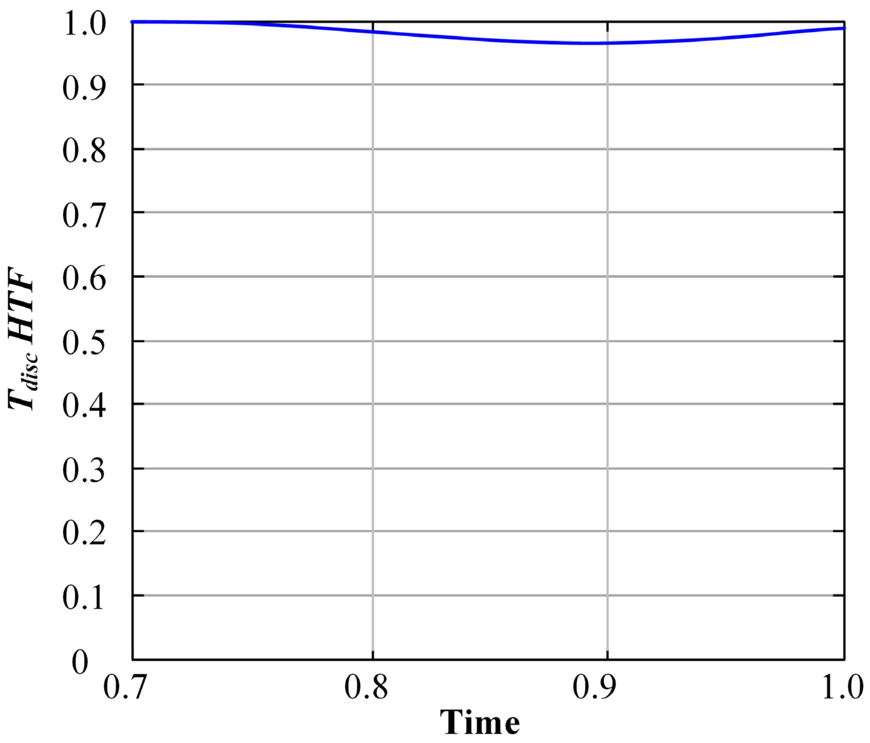
4.2.3. Temperature Degradation

Finally, the discharge dimensionless temperature monitoring for the first simulation cycle was examined, as shown in Figure 12.
The temperature degradation is not considerable, reaching a maximum decrease of 3.236%. Therefore, the proposed design was validated regarding its low-temperature degradation rate at the outlet, and no modifications are required.

5. Conclusions

The present investigation satisfactorily evaluates the feasibility of designing and implementing an innovative thermocline thermal storage system for small-scale off-grid projects. Using a dimensionless heat transfer analysis, the proposed numerical model validates the TES system’s thermal behavior. Its resolution is developed in MATLAB R2018b using the methodology of finite volumes in implicit formulation, and it was validated with experimental data. Furthermore, the proposed resolution of the model is adequate to achieve consistent results for any type of tank due to the thermocline, materials, geometry, and multiple configurable parameters.
The resolution of the numerical model allows for establishing a correlation of efficiency concerning the geometric parameters and the monitoring of temperature degradation. Based on this, a methodology was established for sizing a TES. In addition, the thermal storage system components that established a compact design for high temperatures were identified: a Stirling engine as a power block (PB), AlSi12 as an energy accumulator PCM, and Cerrolow 117 as a heat transfer fluid. Based on this, the block-structured configuration with multiple tunnels was defined as the most compatible to integrate these components, both in constructive aspects and to minimize the thermal fatigue produced on the tank walls.
Finally, the operational parameters of the storage tank were determined, and its thermal behavior was simulated for ten cycles, noting a rapid stabilization of the boundary conditions, a storage efficiency of 92.22%, and a maximum temperature degradation in the discharge of 3.24%. Additionally, the storage time is 13 [h] for 384.8 [kWh] of storage in a volume of 0.809 [m3] of PCM material. Hence, in the case study application, it was proposed to use the thermal storage system, coupled to the Stirling engine and a concentrated solar power (CSP), for a continuous power supply plant to a pumping system, used to control infiltration through a battery of wells in a tailings dam in copper mining. Using the information available in SERNAGEOMIN, the system sizing was carried out. The proposed integral solution covers 33.13% of the total pumping capacity requirement.

Author Contributions

Conceptualization, S.M.N. and Y.M.M.; Methodology, S.M.N., F.E.T.P. and Y.M.M.; Software, F.E.T.P. and Y.M.M.; Validation, F.E.T.P. and Y.M.M.; Formal analysis, S.M.N., F.E.T.P. and Y.M.M.; Investigation, S.M.N., F.E.T.P. and Y.M.M.; Resources, Y.M.M.; Data curation, F.E.T.P.; Writing—original draft, S.M.N.; Writing—review & editing, Y.M.M.; Visualization, Y.M.M.; Supervision, S.M.N. and Y.M.M.; Project administration, S.M.N. and Y.M.M. All authors have read and agreed to the published version of the manuscript.

Funding

This research received no external funding.

Institutional Review Board Statement

Not applicable.

Informed Consent Statement

Not applicable.

Data Availability Statement

The data presented in this study are available in the article.

Acknowledgments

The researchers gratefully acknowledge the Chemical and Mechanical Engineering Schools at the Pontificia Universidad Católica de Valparaíso (PUCV) and the Undergraduate Program of Civil Mechanical Engineering at PUCV for their support during the execution of this research.

Conflicts of Interest

The authors declare no conflicts of interest.

Nomenclature

Athe sectional area of the tankGreek Symbols
Aijmatrix of advective and diffusive termsΘdimensionless temperature
Biimatrix of conductive termsΛdimensionless thermal flow
Cspecific heatΠdimensionless charging/discharging period
Cicoupling matrix for the solid fill materialΨdimensionless time
CFinertial dimensionless coefficientδboundary layer thickness
Dlarger diameter ϵ porosity
Diresolution matrix for the solid fill materialζproportion of liquid mass with respect to total mass
Esingular matrixηthermal storage efficiency
EX,Ψdimensionless energyρdensity
Firesolution matrix for heat transfer fluid H dimensionless fractional heat capacitance ratio
fform factorSubscripts
HheightCcold
kthermal conductivity discdischarge
m ˙ mass flow ffluid
nnumber of nodesHhot
ttimeiposition of each node
Ttemperature ininner
Ujdependent variables matrixLlow
Xdimensionless axial coordinatemmelting
outout
rradial
pcmphase change material
sssectional

References

  1. Yuan, H.; Tsukuda, T.; Yang, Y.; Shibata, G.; Kobashi, Y.; Ogawa, H. Effects of Chemical Compositions and Cetane Number of Fischer–Tropsch Fuels on Diesel Engine Performance. Energies 2022, 15, 4047. [Google Scholar] [CrossRef]
  2. Choi, Y.H.; Jang, Y.J.; Park, H.; Kim, W.Y.; Lee, Y.H.; Choi, S.H.; Lee, J.S. Carbon dioxide Fischer-Tropsch synthesis: A new path to carbon-neutral fuels. Appl. Catal. B Environ. 2017, 202, 605–610. [Google Scholar] [CrossRef]
  3. Liu, X.; Zhao, C.; Guo, H.; Wang, Z. Performance Analysis of Ship Exhaust Gas Temperature Differential Power Generation. Energies 2022, 15, 3900. [Google Scholar] [CrossRef]
  4. Trapani, K.; Millar, D.L. Floating photovoltaic arrays to power the mining industry: A case study for the McFaulds lake (Ring of Fire). Environ. Prog. Sustain. Energy 2016, 35, 898–905. [Google Scholar] [CrossRef]
  5. McCormick, P.G.; Suehrcke, H. The effect of intermittent solar radiation on the performance of PV systems. Sol. Energy 2018, 171, 667–674. [Google Scholar] [CrossRef]
  6. Jabir, M.; Illias, H.A.; Raza, S.; Mokhlis, H. Intermittent Smoothing Approaches for Wind Power Output: A Review. Energies 2017, 10, 1572. [Google Scholar] [CrossRef]
  7. Acar, C. A comprehensive evaluation of energy storage options for better sustainability. Int. J. Energy Res. 2018, 42, 3732–3746. [Google Scholar] [CrossRef]
  8. Guo, Y.; Zhang, X.; Yang, L.; Xu, C.; Du, X. The Heat Transfer of Microencapsulated Phase Change Material Slurry and Its Thermal Energy Storage Performance of Combined Heat and Power Generating Units. Energies 2017, 10, 1662. [Google Scholar] [CrossRef]
  9. Wang, K.; Qin, Z.; Tong, W.; Ji, C. Thermal Energy Storage for Solar Energy Utilization: Fundamentals and Applications. In Renewable Energy—Resources, Challenges and Applications; Al Qubeissi, M., El-kharouf, A., Soyhan, H.S., Eds.; IntechOpen: Rijeka, Croatia, 2020. [Google Scholar] [CrossRef]
  10. Calise, F.; D’Accadia, M.; Barletta, C.; Battaglia, V.; Pfeifer, A.; Duic, N. Detailed Modelling of the Deep Decarbonisation Scenarios with Demand Response Technologies in the Heating and Cooling Sector: A Case Study for Italy. Energies 2017, 10, 1535. [Google Scholar] [CrossRef]
  11. Khoshbaf, M.J.; Orozco, J.C. Thermal Energy Storage in CSP Technologies: From Commercialized to Innovative Solutions; French National Center for Scientific Research: Paris, France, 2018. [Google Scholar] [CrossRef]
  12. Sarbu, I.; Sebarchievici, C. A Comprehensive Review of Thermal Energy Storage. Sustainability 2018, 10, 191. [Google Scholar] [CrossRef]
  13. Leśko, M.; Bujalski, W.; Futyma, K. Operational optimization in district heating systems with the use of thermal energy storage. Energy 2018, 165, 902–915. [Google Scholar] [CrossRef]
  14. Li, B.; Zhang, J.; Yan, H.; Zhou, N.; Li, M.; Liu, H. Numerical investigation into the effects of geologic layering on energy performances of thermal energy storage in underground mines. Geothermics 2022, 102, 102403. [Google Scholar] [CrossRef]
  15. Steinmann, W.-D. Thermal energy storage systems for concentrating solar power (CSP) technology. In Advances in Thermal Energy Storage Systems; Elsevier: Amsterdam, The Netherlands, 2015; pp. 511–531. [Google Scholar] [CrossRef]
  16. Codd, D.S.; Gil, A.; Manzoor, M.T.; Tetreault-Friend, M. Concentrating Solar Power (CSP)—Thermal Energy Storage (TES) Advanced Concept Development and Demonstrations. Curr. Sustain. Renew. Energy Rep. 2020, 7, 17–27. [Google Scholar] [CrossRef]
  17. Liu, M.; Tay, N.H.S.; Bell, S.; Belusko, M.; Jacob, R.; Will, G.; Saman, W.; Bruno, F. Review on concentrating solar power plants and new developments in high temperature thermal energy storage technologies. Renew. Sustain. Energy Rev. 2016, 53, 1411–1432. [Google Scholar] [CrossRef]
  18. Alva, G.; Lin, Y.; Fang, G. An overview of thermal energy storage systems. Energy 2018, 144, 341–378. [Google Scholar] [CrossRef]
  19. Chang, Z.; Li, X.; Xu, C.; Chang, C.; Wang, Z.; Zhang, Q.; Liao, Z.; Li, Q. The effect of the physical boundary conditions on the thermal performance of molten salt thermocline tank. Renew. Energy 2016, 96, 190–202. [Google Scholar] [CrossRef]
  20. Ghezelbash, G.; Babaelahi, M.; Saadatfar, M. New analytical solution and optimization of a thermocline solar energy storage using differential quadrature method and genetic programming. J. Energy Storage 2022, 52, 104806. [Google Scholar] [CrossRef]
  21. Stengler, J.; Linder, M. Thermal energy storage combined with a temperature boost: An underestimated feature of thermochemical systems. Appl. Energy 2020, 262, 114530. [Google Scholar] [CrossRef]
  22. Faraj, K.; Khaled, M.; Faraj, J.; Hachem, F.; Castelain, C. Phase change material thermal energy storage systems for cooling applications in buildings: A review. Renew. Sustain. Energy Rev. 2020, 119, 109579. [Google Scholar] [CrossRef]
  23. Faas, S.; Thorne, L.; Fuchs, E.; Gilbertsen, N. 10 MW/sub e/Solar Thermal Central Receiver Pilot Plant: Thermal Storage Subsystem Evaluation. Final Report; Sandia National Lab.: Livermore, CA, USA, 1986. [Google Scholar] [CrossRef]
  24. Wu, M.; Li, M.; Xu, C.; He, Y.; Tao, W. The impact of concrete structure on the thermal performance of the dual-media thermocline thermal storage tank using concrete as the solid medium. Appl. Energy 2014, 113, 1363–1371. [Google Scholar] [CrossRef]
  25. Van Lew, J.T.; Li, P.; Chan, C.L.; Karaki, W.; Stephens, J. Transient Heat Delivery and Storage Process in a Thermocline Heat Storage System. In Proceedings of the ASME 2009 International Mechanical Engineering Congress and Exposition: Volume 6: Emerging Technologies: Alternative Energy Systems; Energy Systems: Analysis, Thermodynamics and Sustainability, Lake Buena Vista, FL, USA, 13–19 November 2009; pp. 139–148. [Google Scholar] [CrossRef]
  26. Wen, P.; Van, J.; Karaki, W.; Lik, C.; Stephens, J.; James, E. Transient Heat Transfer and Energy Transport in Packed Bed Thermal Storage Systems. In Developments in Heat Transfer; Dos Santos Bernardes, M.A., Ed.; InTech: Rijeka, Croatia, 2011. [Google Scholar] [CrossRef]
  27. Xu, C.; Wang, Z.; He, Y.; Li, X.; Bai, F. Sensitivity analysis of the numerical study on the thermal performance of a packed-bed molten salt thermocline thermal storage system. Appl. Energy 2012, 92, 65–75. [Google Scholar] [CrossRef]
  28. Strasser, M.N.; Selvam, R.P. A Cost and Performance Comparison of Packed Bed and Structured Thermocline Thermal Energy Storage Systems. Sol. Energy 2014, 108, 390–402. [Google Scholar] [CrossRef]
  29. Gokon, N.; Yamaguchi, T.; Kodama, T. Cyclic thermal storage/discharge performances of a hypereutectic Cu-Si alloy under vacuum for solar thermochemical process. Energy 2016, 113, 1099–1108. [Google Scholar] [CrossRef]
  30. Risueño, E.; Faik, A.; Gil, A.; Rodríguez-Aseguinolaza, J.; Tello, M.; D’Aguanno, B. Zinc-rich eutectic alloys for high energy density latent heat storage applications. J. Alloys Compd. 2017, 705, 714–721. [Google Scholar] [CrossRef]
  31. Koide, H.; Kurniawan, A.; Takahashi, T.; Kawaguchi, T.; Sakai, H.; Sato, Y.; Chiu, J.N.W.; Nomura, T. Performance analysis of packed bed latent heat storage system for high-temperature thermal energy storage using pellets composed of micro-encapsulated phase change material. Energy 2022, 238, 121746. [Google Scholar] [CrossRef]
  32. Kenisarin, M.M. High-temperature phase change materials for thermal energy storage. Renew. Sustain. Energy Rev. 2010, 14, 955–970. [Google Scholar] [CrossRef]
  33. Liang, H.; Niu, J.; Gan, Y. Performance optimization for shell-and-tube PCM thermal energy storage. J. Energy Storage 2020, 30, 101421. [Google Scholar] [CrossRef]
  34. Elfeky, K.E.; Li, X.; Ahmed, N.; Lu, L.; Wang, Q. Optimization of thermal performance in thermocline tank thermal energy storage system with the multilayered PCM(s) for CSP tower plants. Appl. Energy 2019, 243, 175–190. [Google Scholar] [CrossRef]
  35. Schumann, T.E.W. Heat transfer: A liquid flowing through a porous prism. J. Frankl. Inst. 1929, 208, 405–416. [Google Scholar] [CrossRef]
  36. Pacheco, J.E.; Showalter, S.K.; Kolb, W.J. Development of a Molten-Salt Thermocline Thermal Storage System for Parabolic Trough Plants. J. Sol. Energy Eng. 2002, 124, 153–159. [Google Scholar] [CrossRef]
  37. Hoffmann, J.-F.; Fasquelle, T.; Goetz, V.; Py, X. A thermocline thermal energy storage system with filler materials for concentrated solar power plants: Experimental data and numerical model sensitivity to different experimental tank scales. Appl. Therm. Eng. 2016, 100, 753–761. [Google Scholar] [CrossRef]
  38. Van Lew, J.T.; Li, P.; Chan, C.L.; Karaki, W.; Stephens, J. Analysis of Heat Storage and Delivery of a Thermocline Tank Having Solid Filler Material. J. Sol. Energy Eng. 2011, 133, 021003. [Google Scholar] [CrossRef]
  39. Amano, R.; Sundén, B. (Eds.) Computational Fluid Dynamics and Heat Transfer: Emerging Topics; WIT: Southampton, UK; Boston, MA, USA, 2011. [Google Scholar]
  40. Caliano, M.; Bianco, N.; Graditi, G.; Mongibello, L. Analysis of a phase change material-based unit and of an aluminum foam/phase change material composite-based unit for cold thermal energy storage by numerical simulation. Appl. Energy 2019, 256, 113921. [Google Scholar] [CrossRef]
  41. Bian, Z.; Hou, F.; Bai, Y.; Dong, Q.; Wang, H. Composited phase change material with hierarchical metal foam for efficient thermal energy management. Appl. Therm. Eng. 2024, 236, 121745. [Google Scholar] [CrossRef]
  42. Despotovic, M.; Nedic, V.; Despotovic, D.; Cvetanovic, S. Evaluation of empirical models for predicting monthly mean horizontal diffuse solar radiation. Renew. Sustain. Energy Rev. 2016, 56, 246–260. [Google Scholar] [CrossRef]
  43. LeVeque, R.J. Finite Difference Methods for Ordinary and Partial Differential Equations: Steady-State and Time-Dependent Problems, 1st ed.; Society for Industrial and Applied Mathematics: Philadelphia, PA, USA, 2007. [Google Scholar] [CrossRef]
  44. Comisión Nacional de Energía del Gobierno de Chile, Balance nacional de energía—Energía Abierta|Comisión Nacional de Energía. 2021. Available online: http://energiaabierta.cl/visualizaciones/balance-de-energia/ (accessed on 28 March 2023).
  45. Sernageomin, Decreto 86: Reglamento de Construcción y Operación de Tranques de Relaves. 2007. Available online: https://www.bcn.cl/leychile/navegar?idNorma=193450 (accessed on 10 April 2023).
  46. Mapas de Localización Depósito de Relaves, SERNAGEOMIN (n.d.). Available online: https://www.sernageomin.cl/mapas-de-localizacion-deposito-de-relaves/ (accessed on 14 April 2023).
  47. MAPA_PICA_500K.jpg (2244 × 2953), (n.d.). Available online: https://www.sernageomin.cl/pdf/mineria/relaves/MAPA_PICA_500K.jpg (accessed on 14 April 2023).
  48. Explorador Solar; n.d. Available online: https://solar.minenergia.cl/inicio (accessed on 2 April 2024).
  49. Neises, T.; Wagner, M.J. Simulation of Direct Steam Power Tower Concentrated Solar Plant. In Proceedings of the ASME 2012 6th International Conference on Energy Sustainability, Parts A and B, American Society of Mechanical Engineers, San Diego, CA, USA, 23–26 July 2012; pp. 499–507. [Google Scholar] [CrossRef]
  50. Battleson, K. Solar Power Tower Design Guide: Solar Thermal Central Receiver Power Systems. A Source of Electricity and/or Process Heat; Sandia National Lab.: Livermore, CA, USA, 1981. [Google Scholar] [CrossRef]
  51. Blair, N.; DiOrio, N.; Freeman, J.; Gilman, P.; Janzou, S.; Neises, T.; Wagner, M. System Advisor Model (SAM) General Description (Version 2017.9.5). 2018. Available online: https://www.nrel.gov/docs/fy18osti/70414.pdf (accessed on 18 April 2023).
  52. Laube, T.; Marocco, L.; Niedermeier, K.; Pacio, J.; Wetzel, T. Thermodynamic Analysis of High-Temperature Energy Storage Concepts Based on Liquid Metal Technology. Energy Technol. 2020, 8, 1900908. [Google Scholar] [CrossRef]
Figure 1. Temperature distributions in the tank axis comparing modeling predicted results with experimental data from [36].
Applsci 14 03690 g001
Figure 2. Comparison of the dimensionless temperature distribution after 2.5 [h] of loading for different numbers of nodes.
Applsci 14 03690 g002
Figure 3. Comparison of dimensionless temperature distribution after 2.5 [h] of loading between different time steps.
Applsci 14 03690 g003
Figure 4. Thermal storage system designed as part of a comprehensive TES + CSP solution.
Applsci 14 03690 g004
Figure 5. Extract from the tailings distribution map, Commune of Pica, Region of Tarapacá, Chile [47].
Applsci 14 03690 g005
Figure 6. Solar renewable resource for the case of study: (a) Location from Solar Explorer Map, Commune of Pica; (b) DNI for a representative daily cycle per month [48].
Applsci 14 03690 g006
Figure 7. Time-dependent thermal power balance.
Applsci 14 03690 g007
Figure 8. Diagram of flow components in the TES, similar to that proposed by [52].
Applsci 14 03690 g008
Figure 9. Cross section of the designed tank.
Applsci 14 03690 g009
Figure 10. HTF dimensionless temperature distribution for discharge and charge cycles Nº1, Nº5, and Nº10, proposed design.
Applsci 14 03690 g010
Figure 11. Thermal efficiency (η) versus H/D for the proposed design.
Applsci 14 03690 g011
Figure 12. HTF dimensionless temperature history at outlet X = 1 for the first discharge cycle.
Applsci 14 03690 g012
Table 1. Operating parameters of the experimental thermocline tank from Reference [36].
ParameterValueUnit
Capacity2.3[MWh]
Working FluidSolar Molten Salt-
Solid fill materialQuartzite rock and silica sand-
Insulating materialFiberglass-
Insulating layer23[cm]
Discharge time2.5[h]
Tank height6.1[m]
Tank diameter3[m]
Volume42[m3]
Porosity0.22-
Particle diameter0.0191[m]
Mass flow5.46[kg/s]
TH396[°C]
TC289[°C]
Time Interval0.5[h]
ConfigurationPorous bed-
Table 2. Statistical indicators on the error produced between experimental data and those calculated by the model.
t [h]MAERMSEMRAERRMSE [%]
0.50.0630.0790.1105.650
1.00.0500.0750.2755.987
1.50.0330.0430.1063.811
2.00.0340.0390.3935.055
2.50.0710.0900.5356.514
Table 3. Main parameters of the proposed design for the TES.
ParameterValueUnit
Capacity384.8[kWh]
Working fluidCerrolow 117-
PCM materialAlSi12-
Thermal Conductivity121[W/mK]
Melting Point (average)578[°C]
Specific Heat Capacity963[J/kg K]
Density2.66[g/cm3]
Latent Heat of Fusion389[J/g]
Download time13[h]
Loading time13[h]
Tank height1.8[m]
Tank diameter0.85[m]
Volume0.81[m3]
Porosity0.21-
Mass flow 0.49[kg/s]
TH600[°C]
TC290[°C]
ConfigurationBlock with multiple tunnels-
Disclaimer/Publisher’s Note: The statements, opinions and data contained in all publications are solely those of the individual author(s) and contributor(s) and not of MDPI and/or the editor(s). MDPI and/or the editor(s) disclaim responsibility for any injury to people or property resulting from any ideas, methods, instructions or products referred to in the content.

