
Compact and Highly Isolated Continuous Scanning Dual-Polarized Holographic Antenna Using a Pillbox Feeding Structure

1
Department of Electrical and Electronic Engineering, Yonsei University, Seoul 03722, Republic of Korea
2
Department of Electrical Engineering, Chungnam National University, Daejeon 34134, Republic of Korea
*
Author to whom correspondence should be addressed.
Appl. Sci. 2024, 14(9), 3644; https://0-doi-org.brum.beds.ac.uk/10.3390/app14093644
Submission received: 17 March 2024
/
Revised: 22 April 2024
/
Accepted: 23 April 2024
/
Published: 25 April 2024
(This article belongs to the Special Issue Technology and Application of Microwave Communication and Antenna Design)
Abstract
:In this paper, we propose a novel approach to realize a compact and highly isolated dual-polarized holographic antenna using a pillbox feeding structure. The proposed antenna feeds dual orthogonal surface waves with low distortion phase distribution and high isolation through a compact three-layer pillbox feeding structure. This antenna also consists of a shared aperture dual-polarized hologram pattern calculated to radiate the objective wave in the desired direction without increasing the antenna size. As a result, the proposed holographic antennas (HA) have a compact size and support forward-to-backward continuous scanning with minimal gain degradation. The simulated and measured results are in good agreement, validating the efficiency of the proposed antenna design, which has the ability to scan the beam direction from +18° to −25°, passing through the broadside within the frequency range of 21–27 GHz. Finally, the proposed antenna has a broadside gain of 18.5 dBi in each polarization and a gain variation of less than 2 dB within the operating bandwidth.
1. Introduction
Holographic antennas (HAs) consist of and operate with a hologram pattern synthesized by the interferometry of a reference wave and an objective wave. These characteristics provide a simple design procedure for adjusting the hologram pattern and achieving the desired radiation pattern and polarization characteristics [1,2,3,4,5,6,7,8,9,10,11,12,13]. In addition, HAs are characterized by distinct advantages such as low profile, high directivity, and frequency scanning capability, thereby satisfying the requirements of systems for signal transmission and reception in various communication environments in the next generation beyond 5G/6G communication environments and wireless power transfer systems [4,5]. Therefore, as the need for the development of HAs in various systems and applications is rapidly increasing, various studies such as those on beam-scannable HAs, polarization-diverse HAs, and multi-beam HAs have been conducted to address this demand [1,2,3,5,6,7].
In particular, there are many requirements for the development of HAs in the implementation of full-duplex systems capable of large data transmissions by exploiting polarization diversity and beamforming [8]. Therefore, a single antenna structure with dual-polarization characteristics, high isolation, and the ability to realize different beam patterns at each polarization is essential. Consequently, several dual-polarized HAs have recently been investigated for these applications [10,11,12,13] to provide a viable solution for reducing the fabrication complexity and antenna profile of millimeter-wave systems. However, the design of the previously proposed dual-polarized HAs faces unique challenges.
To ensure appropriate radiation characteristics, the reference surface waves satisfying dual polarization should use feeding structures that travel in orthogonal directions to each other without any interference between the polarizations. Previous studies used orthogonally placed parallel plate waveguides (PPWs) [10,11,12] or substrate-integrated waveguide (SIW) horn arrays [13] to generate plane reference waves in orthogonal directions. However, the feeding methods used, including orthogonally placed PPWs and SIW horn arrays, suffer from increased coupling and low isolation between the feeding ports due to the reference wave feeding structures located near the radiating apertures [10,11,12]. In addition, in the case of the array system, each feeding element necessitates a large space, thereby increasing system size [13]. To overcome these drawbacks, a previous study used a pillbox feeding structure in a single-polarization HA to minimize the size of the feeding structure, reducing the overall antenna size [14,15].
However, the conventional pillbox feeding structure is only designed for single-polarized HAs, rendering it difficult to support dual-polarized HAs [14]. Therefore, an innovative compact feeding structure suitable for dual-polarized HAs must be designed. In addition, it is necessary to develop a novel structure using the pillbox design to ensure high isolation and low cross polarization. As a result, the proposed dual-polarized HA suppresses the open stopband (OSB) phenomenon during continuous scanning in each polarization, thereby preventing a decrease in radiation efficiency, especially in the broadside direction [13].
To overcome all the above drawbacks and design an HA with a compact structure, this study presents the design of an HA that employs a low phase distortion feeding structure for high polarization purity and a hologram pattern that has the ability to operate each polarization independently without correlation. The proposed three-layer pillbox feeding structure generates independent orthogonal reference waves traveling along the radiation aperture to feed the hologram pattern with two orthogonal fields. Furthermore, each polarization field is separated into a different layer to improve isolation between the feeding ports. The hologram pattern is composed of Jerusalem cross-shaped unit cells and operates independently at dual polarizations, radiating fields at each polarization. The combination of the two components suppresses the radiation of unwanted cross-polarized fields to solve the OSB phenomenon and design a dual-polarized HA that can support dual polarization with continuous scanning. In addition, the antenna was fabricated using a printed circuit board (PCB) etching process and all layers were bonded to form a multilayer structure. The radiation characteristics of the proposed antenna were verified by simulations and measurements.
2. Compact Dual-Polarized Pillbox Feeding Structure with High Isolation
The dual-polarization characteristic requires that polarizations in a single aperture should operate independently of each other. To achieve this requirement, conventional antennas implementing dual polarization use dipoles in different directions; however, the problem is that dipoles for different polarizations cannot share the same position, thereby halving the actual usable aperture [16]. Conversely, HA is well suited for implementing dual polarization because the appropriate behavior of each polarization can be ensured regardless of the different patterns being superimposed. To design a dual-polarized HA, we need unit cells that can behave independently but also share a single structure. Figure 1 shows a schematic of the proposed dual-polarized HA for three-dimensional full-wave simulation operated by two orthogonally polarized reference waves propagating along the x- and y-axes.
To achieve the desired HA radiation characteristics, the feeding system should produce a surface wave with low phase distortion. In particular, frequency beam scanning HAs require a plane wave as the reference wave. Conventional beam scanning dual-polarized HAs use dividing networks and feed antenna arrays to generate plane waves in a wide aperture [10]. However, this approach requires a large area that should be comparable to the aperture size and the location of the feeding structures for orthogonal polarizations in the same plane leads to high coupling effects between the polarizations. It also introduces phase distortion, resulting in high cross-polarization levels, which significantly degrade the radiation efficiency when the beam is scanned across the broadside. Furthermore, to achieve continuous scanning without gain degradation, it is necessary to design a structure that can minimize the radiation of unwanted cross-polarized radiation fields. Therefore, to overcome these problems, we propose a novel dual-polarized three-layer pillbox feeding structure that can effectively solve the increased size, low isolation, and gain degradation at the broadside encountered in conventional dual-polarized HAs.
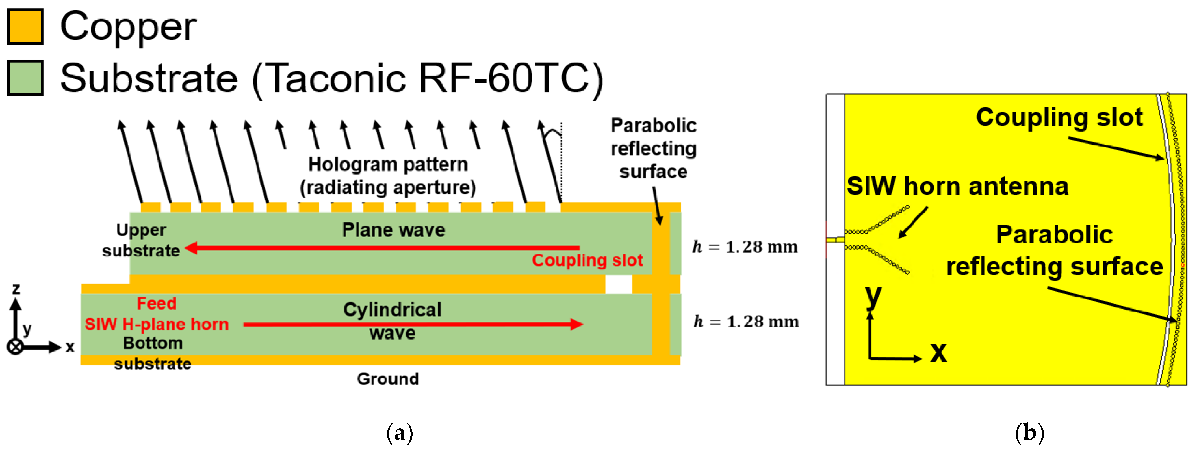
Figure 2 shows the conventional single-polarized HA using the pillbox feeding structure [17]. It is shown that the pillbox feeding structure consists of two layers of the same height Taconic RF-60TC ( = 6.15, = 0.002) substrate. In the bottom layer, the SIW H-plane sectoral horn is integrated as a feeder. As shown in Figure 2a, the SIW horn is excited by the edge end launcher to send a cylindrical guided wave into the bottom substrate. Subsequently, the guided wave is reflected by an integrated parabolic reflecting surface consisting of metal vias connecting the bottom and top coppers. In addition, the coupling slot connects the bottom and top layers; it is positioned in front of the reflecting surface at λg/2, and has the same length as the reflecting surface. Therefore, the reflecting surface acts as a 180° coupler between the bottom and top substrates and also converts the cylindrical wave into a plane wave. In addition, Figure 2b shows the upper view of the single-polarized pillbox feeding structure. However, as mentioned previously, the conventional pillbox feeding structure is designed only for single-polarization antennas. Thus, it needs to be modified to a novel design to satisfy dual polarization.
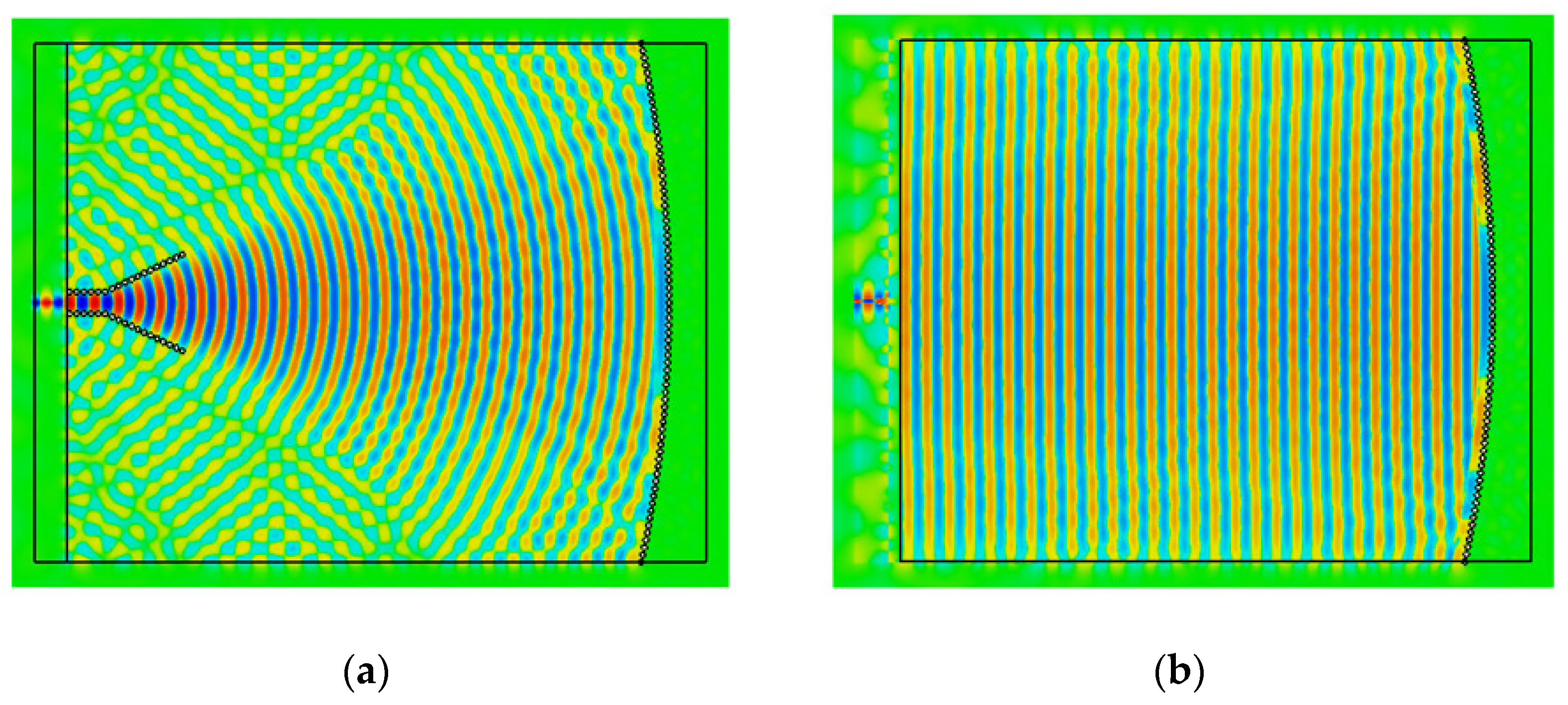
Figure 3 shows the field distribution of the pillbox feeding structure on the bottom and top substrates. Figure 3a shows the cylindrical wave fed from the SIW horn antenna on the bottom substrate. Figure 3b shows the converted plane wave by the parabolic reflecting surface on the top substrate. This shows that a plane wave with a constant phase is realized over a wide aperture.
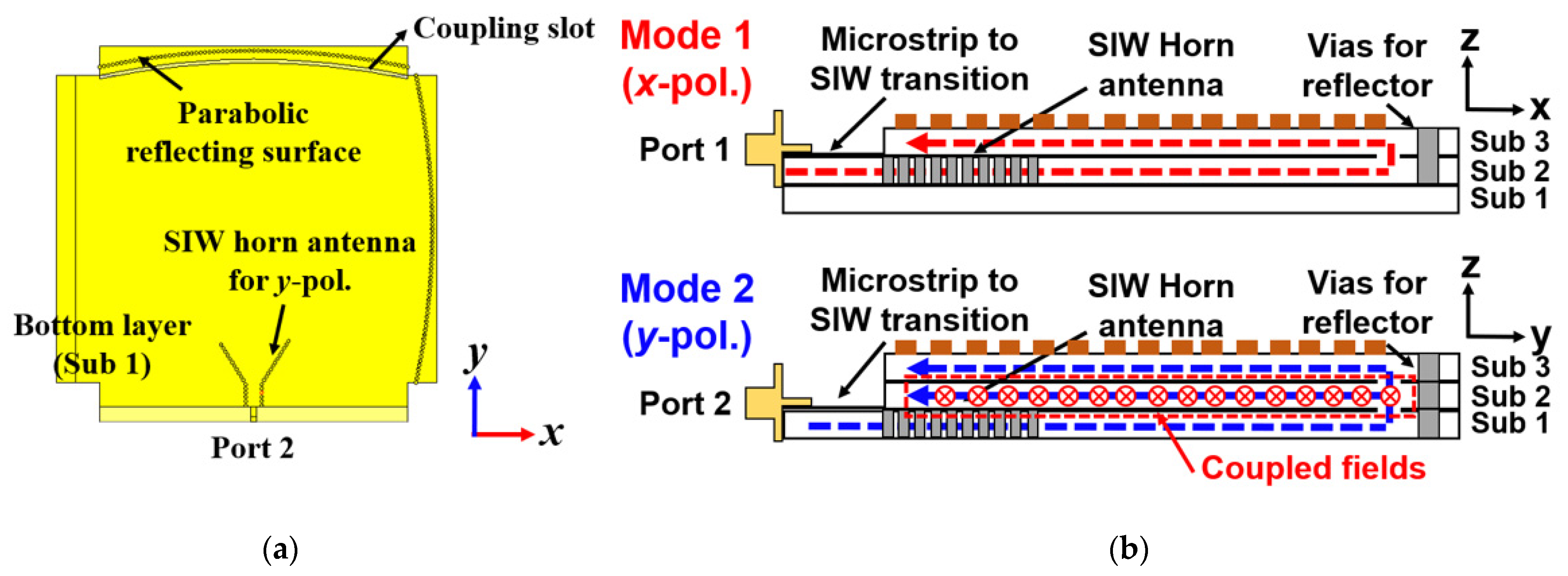
Figure 4 shows the newly designed three-layer pillbox feeding structure for dual polarization. To generate two orthogonal surface waves while maintaining a compact size, two pillbox structures are stacked orthogonally. It is constructed by stacking one more dielectric substrate underneath the structure shown in Figure 2b. However, by simply overlapping the pillboxes of the two polarizations, the field of the y-polarization can also be transferred to the middle layer (Sub 2), where port 1 is located, as shown in Figure 4b, causing coupling effects between the ports and rendering it difficult to achieve the high isolation required to realize a full-duplex system. In addition, field components with overlapping feeding paths add to each other, resulting in plane wave polarization distortion and low cross-polarization levels, thereby confirming the necessity of a new feeding structure design to avoid these problems. As shown in Figure 4b, the x- and y-polarized fields are fed from the lower layers (Sub 1, Sub 2). As described earlier, the field fed from the lower and middle layers is initially converted into a cylindrical wave by the proposed pillbox structure and then into a plane wave by the parabolic reflecting surface realized by the vias. The field is also coupled to the top layer (Sub 3) through a coupling slot located at /2 away from the tube wavelength. The converted plane wave then travels along the dielectric substrate.
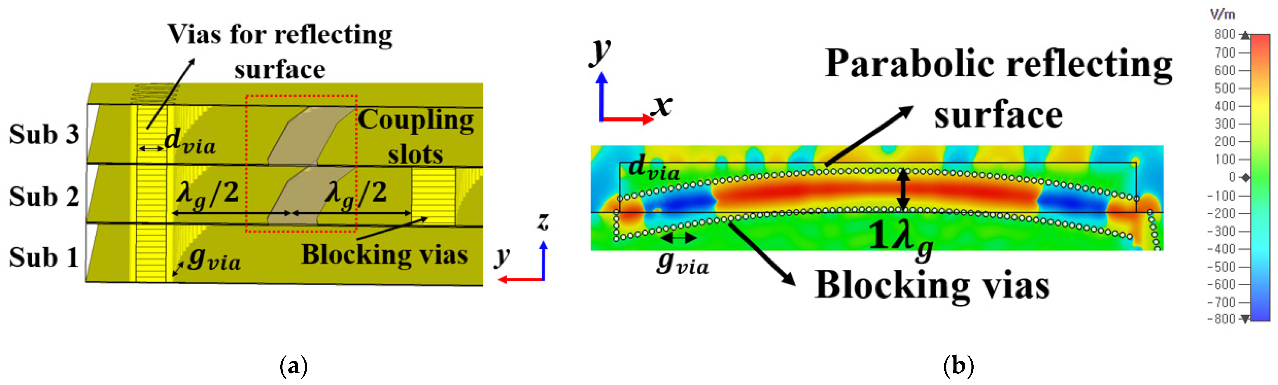
Figure 5 shows the proposed pillbox feeding structure for high isolation using blocking vias. As shown in Figure 5a, the blocking vias are located on the opposite side of the parabolic reflecting surface for preventing field propagation onto the middle layer (Sub 2); the distance between the blocking via and the reflecting surface is. Furthermore, Figure 5b demonstrates that the blocking vias allow the two polarization fields to be physically separated by different layers. Therefore, the path of the field propagating to the middle layer is blocked by the additional blocking via. Consequently, the newly proposed pillbox feeding structure with additional blocking vias can achieve high isolation in a compact size without increasing the size.
Figure 6 shows the detailed configuration and effects of the added blocking via. As shown in Figure 6a, the blocking via is placed on the opposite side of the y-polarized parabolic reflecting surface to avoid interference with the formation of the implemented plane wave. In addition, since reflected and propagating fields should have the same phase and be transmitted to the upper dielectric, they are placed in the coupling slot at a distance of . The diameter of the via () was set to 1 mm and the spacing between the vias () was 1.3 mm. On the left side of the blocking via, vias were placed to avoid field propagation in the middle layer. In contrast, the right side of the blocking via was arranged asymmetrically because the x-polarized reflecting surface not only affects the via arrangement but also suppresses the field flow in the reflecting surface itself. Figure 6b shows the simulated results of the field distribution by the blocking vias. The fields of the lower layers cannot be coupled to the second layer where the x-polarized feed horn is located. The blocking vias physically separate the fields.
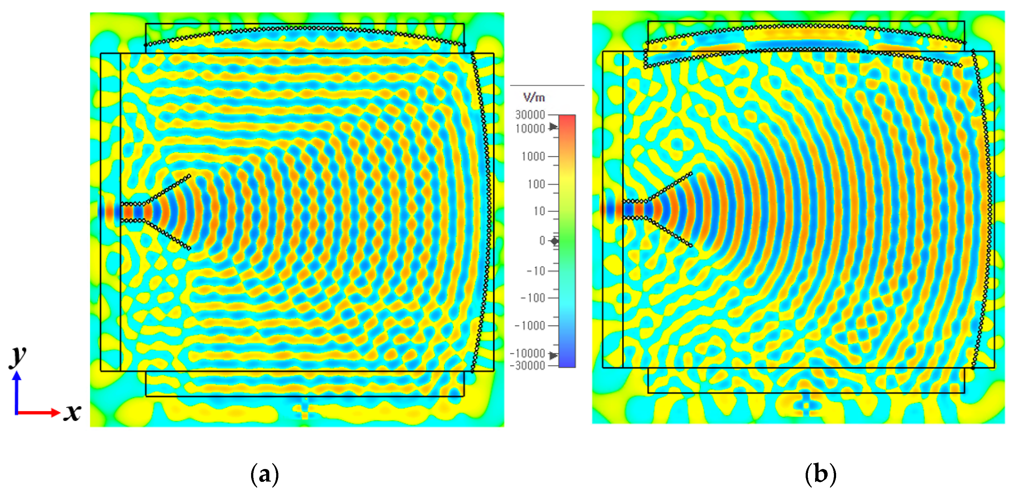
Moreover, Figure 7 exhibits the field distributions on the middle layer (Sub 2) with and without blocking vias. As shown in Figure 7a, the y-polarized fields reflected from the parabolic reflecting surface combine with the x-polarized fields, degrading the isolation and causing phase distortion. Conversely, Figure 7b demonstrates that fields separated by blocking vias cannot be coupled with orthogonally polarized fields. As a result, the feed horn antenna can produce a low-distortion cylindrical wave. In addition, the proposed dual-polarized HA can achieve high isolation because of the low coupling between each port.
Figure 8 shows a comparison of the simulated results with and without blocking vias in the middle layer and it shows that the isolation between the feed ports (S21) is approximately 15 dB larger than that without the blocking vias. However, previous field distribution results represent guided waves inside the waveguide. Therefore, the feeding structure should use a metasurface of the unmodulated impedance surface to convert it to a surface wave simulation and verify the phase progression.
Figure 9 presents the field distribution results on the top layer using a metasurface. Figure 9a illustrates the field distribution resulting from the propagation of a surface wave in a metasurface with an unmodulated surface impedance. The cylindrical wave from the SIW horn antenna is reflected by the reflector on the under layers (Sub 1 or Sub 2) and produces a plane wave at the top layer (Sub 3). Furthermore, once the coupled field from the lower layers is integrated into the upper layer, it is subsequently converted by the metasurface into a TM0 mode surface wave that acts as a reference wave, as shown in Figure 9a. In addition, Figure 9b,c shows the phase distribution of the surface wave corresponding to each polarization mode. In particular, the phase distribution in each mode acts as a plane wave perpendicular to the direction of wave propagation. As a result, plane waves with an accurate phase can be realized, suppressing unwanted radiation and enabling continuous scanning in various directions, including the broadside, with a high gain.
3. Dual-Polarized Hologram Pattern with Anisotropic Surface Impedance
The top layer of the antenna consists of the hologram pattern, which is composed of an impedance surface using subwavelength metasurfaces. Equation (1) defines the surface impedance of the hologram pattern [1]:
where and represent the reference and the desired objective wave, respectively, and and reflect the normalized average surface impedance and modulation index, respectively. We chose a commercial dielectric substrate (Taconic RF-60TC, = 6.15, tan δ = 0.002, h = 1.28 mm) to satisfy the range of surface impedance. In addition, we selected appropriate values for the hologram pattern parameters, namely = 1.3 and = 0.15, to achieve high directivity and appropriate impedance matching characteristics in a compact size. By using the selected values on a commercial substrate, the size of the antenna can be reduced without using a metasurface matching structure, which is a prerequisite in conventional HAs [14].
Figure 10 illustrates the unit cells for the dual-polarized hologram pattern. The unit cell has a shape in which two strips are arranged crosswise. The surface impedance varies with the length of the dimension of the unit cell. The red and yellow strips represent the x- and y-polarized hologram patterns, respectively. Each of these cells is assembled in the top layer of the proposed HA and forms a dual-polarized hologram pattern. To suppress the OSB phenomenon, it is effective to use a unit cell with anisotropic properties to suppress the radiation field from unwanted cross polarization [8,12]. For the same purpose, in accordance with [12], we used a cross-shaped anisotropic unit cell, which is very stable due to the absence of any surface impedance changes in cross polarization that could independently adjust surface impedance in both polarizations. In addition, the stable cross-polarized surface impedance does not represent a modulating surface, which can prevent unwanted cross-polarized radiation.
Figure 11 shows the shape and characteristics of the unit cell. Figure 11a shows the length of each element of the unit cell. Figure 11b shows the variation in the surface impedance of the co-polarized and cross-polarized waves with varying lengths of and for the Jerusalem cross-unit cell. Also, the black and red curves represent the surface impedance at co- and cross-polarization, respectively. The cross-polarized surface impedance maintains a constant impedance with changing co-polarized surface impedance. This in turn represents an unmodulated impedance surface in cross-polarization, which suppresses radiation from cross-polarized fields, similar to OSB in conventional HA [8].
Figure 12 shows the field distribution in the XZ plane when the proposed antenna radiates forward, broadside, and backward. Figure 12a shows the field distribution when radiating forward +14 degrees at 22 GHz. Also, as shown in Figure 12b, the proposed antenna radiates broadside at 23.5 GHz. Finally, the proposed antenna radiates in the backward direction −24° at 27 GHz as shown in Figure 12c.
Figure 13 shows the simulated radiation patterns in the XZ (x-polarization) and YZ (y-polarization) planes. In each plane, the radiation patterns are shown in the same direction. Radiation patterns vary from +22° to −24° over the range of 21–27 GHz.
4. Fabrication, Measurement Results, and Comparison
Figure 14 shows an image of the fabricated prototype antenna. The magnified views within the red and black dotted boxes illustrate the realized hologram pattern using Jerusalem cross-shaped unit cells. To verify the results of the simulation, we fabricated a prototype antenna using the PCB process with a tolerance of 10 microns.
Figure 15 shows the comparison between the simulated and measured S-parameters of the proposed HA, which were measured using an ANRITSU MS4644B vector network analyzer. The reflection coefficients for each polarization were less than −10 dB in the range of 21–27 GHz. In addition, the ports were isolated by approximately 40 dB, confirming the consistency between the simulated and measured results.
In addition, Figure 16 exhibits the measured radiation patterns of the proposed HA. The solid lines represent co-polarized radiation patterns and the dashed lines represent cross-polarized radiation patterns, respectively. The maximum gain in the radiation direction was varied with frequency by exploiting the frequency scanning capability. For the fabricated prototype antenna, the frequency response was shifted by approximately 1 GHz. Restimulations with different permittivity values revealed that the frequency was slightly shifted by the tolerances of the commercial dielectric substrate. In addition, the bonding materials between each substrate affected the effective permittivity. The proposed HA scans continuously from the forward-to-backward direction. In each plane, the radiation patterns are shown with the same patterns and directions. Radiation patterns varied from +18° to −25° over the range of 21–27 GHz. However, when the beam scans to the broadside, the open stopband phenomenon slightly degraded the gain of the antenna compared to other frequencies. Nonetheless, the degradation of the realized gain was less than 2 dB, rendering the continuous scan within a 2-dB gain variation possible. Over the measured frequency range of 21–27 GHz, the realized gain of the proposed HA was found to exceed 18.5 dBi. The radiation patterns were similar in x-polarization and y-polarization.
As a result, the proposed HA realizes a dual-polarized radiation pattern and high isolation between each polarization. The proposed dual-polarized HA has a compact size and a wide scanning range with continuous scanning compared to previous studies, as summarized in Table 1.
5. Conclusions
In this paper, we propose a compact and highly isolated dual-polarized HA with continuous scanning using a pillbox feeding structure. The proposed pillbox structure can generate orthogonal surface waves with high isolation between low distortion in two polarizations with compact size. The hologram pattern consists of the proposed HA, which acts as an anisotropic impedance surface to control the surface impedance in each polarization independently by using Jerusalem cross-shaped unit cells. This feeding structure and hologram pattern suppress the unwanted cross-polarized fields, thereby overcoming the OSB phenomenon for continuous scanning. The proposed HA is fabricated by PCB etching and bonded with each layer and measures a realized gain of approximately 18.5 dBi in the center frequency. Moreover, it can steer the beam direction from +18° to −25° in the measured range of 21–27 GHz. In addition, the proposed HA has isolation between each polarization over 40 dB. Consequently, the proposed HA can be adapted to various communication systems requiring dual-polarization characteristics with continuous beam scanning through the broadside.
Author Contributions
Data curation and writing—original draft preparation, C.Y.P.; writing—review and editing, C.Y.P., I.-J.Y. and Y.J.Y.; fabrication and measurement, C.Y.P.; supervision, Y.J.Y. All authors have read and agreed to the published version of the manuscript.
Funding
This work was supported by the National Research Foundation of Korea (NRF) grant funded by the Korean government (MSIT) (No. NRF-2022R1F1A1069725).
Institutional Review Board Statement
Not applicable.
Informed Consent Statement
Not applicable.
Data Availability Statement
The original contributions presented in the study are included in the article, further inquiries can be directed to the corresponding author.
Conflicts of Interest
The authors declare no conflicts of interest.
References
- Fong, B.H.; Colburn, J.S.; Ottusch, J.J.; Visher, J.L.; Sievenpiper, D.F. Scalar and Tensor Holographic Artificial Impedance Surfaces. IEEE Trans. Antennas Propag. 2010, 58, 3212–3221. [Google Scholar] [CrossRef]
- Minatti, G.; Caminita, F.; Casaletti, M.; Maci, S. Spiral Leaky-Wave Antennas Based on Modulated Surface Impedance. IEEE Trans. Antennas Propag. 2011, 59, 4436–4444. [Google Scholar] [CrossRef]
- Li, Z.; Cui, W.; Liu, R.; Wang, M.; Fan, C.; Zheng, H.; Li, E. Metantenna Design with One-dimensional Holographic Concept. Int. J. RF Microw. Comput. Aid. Eng. 2021, 31, mmce22536. [Google Scholar] [CrossRef]
- Huang, C.; Hu, S.; Alexandropoulos, G.C.; Zappone, A.; Yuen, C.; Zhang, R.; Renzo, M.D.; Debbah, M. Holographic MIMO Surfaces for 6G Wireless Networks: Opportunities, Challenges, and Trends. IEEE Wirel. Commun. 2020, 27, 118–125. [Google Scholar] [CrossRef]
- Wu, X.; Hou, F.; Li, Y.; Zhao, S.; Zhang, S.; Xue, H.; Chang, M.; Han, J.; Liu, H.; Li, L. Multitarget Wireless Power Transfer System Strategy Based on Metasurface-Holography Multifocal Beams. IEEE Trans. Microw. Theory Tech. 2023, 71, 3479–3489. [Google Scholar] [CrossRef]
- Li, M.; Tang, M.; Xiao, S. Design of a LP, RHCP and LHCP Polarization-Reconfigurable Holographic Antenna. IEEE Access 2019, 7, 82776–82784. [Google Scholar] [CrossRef]
- Liu, J.; Su, T.; Wu, B.; Lv, H. Holographic Design of Leaky-wave Antenna with Gain Controlled Four Beams. Microw. Opt. Technol. Lett. 2019, 61, 638–643. [Google Scholar] [CrossRef]
- Sazegar, M.; Stevenson, R. Holographic Metasurface Antennas with Dynamic Beam Pointing and Polarization Control. In Proceedings of the 2020 IEEE International Symposium on Antennas and Propagation and North American Radio Science Meeting, Montreal, QC, Canada, 5–10 July 2020; pp. 1657–1658. [Google Scholar]
- Park, C.Y.; Kim, D.; Yoon, I.-J.; Yoon, Y.J. Compact Holographic Antenna for Continuous Backward-to-Forward Scanning with Low Cross Polarization Using Anisotropic Cells. IEEE Antennas Wirel. Propag. Lett. 2024, 23, 339–343. [Google Scholar] [CrossRef]
- Li, Y.B.; Li, L.L.; Cai, B.G.; Cheng, Q.; Cui, T.J. Holographic Leaky-Wave Metasurfaces for Dual-Sensor Imaging. Sci. Rep. 2015, 5, 18170. [Google Scholar] [CrossRef] [PubMed]
- Li, Y.B.; Cai, B.G.; Cheng, Q.; Cui, T.J. Isotropic Holographic Metasurfaces for Dual-functional Radiations without Mutual Interferences. Adv. Funct. Mater. 2016, 26, 29–35. [Google Scholar] [CrossRef]
- Yurduseven, O.; Smith, D.R. Dual-Polarization Printed Holographic Multibeam Metasurface Antenna. IEEE Antennas Wirel. Propag. Lett. 2017, 16, 2738–2741. [Google Scholar] [CrossRef]
- Movahhedi, M.; Komjani, N. Dual-Frequency Dual Orthogonal Polarization Wave Multiplexing Using Decoupled Pixels Based on Holographic Technique. Opt. Express 2020, 28, 12424–12438. [Google Scholar] [CrossRef] [PubMed]
- Yurduseven, O.; Lee, C.; Gonzalez-Ovejero, D.; Ettorre, M.; Sauleau, R.; Chattopadhyay, G.; Fusco, V.; Chahat, N. Multibeam Si/GaAs Holographic Metasurface Antenna at W-Band. IEEE Trans. Antennas Propag. 2021, 69, 3523–3528. [Google Scholar] [CrossRef]
- Prasad, D.V.S.; Singh, H.V.; Tripathi, S.; Paltani, P.P. Dual-band Full-duplex Antenna with High Isolation Using Differential Fed and Dual-polarization. Microw. Opt. Technol. Lett. 2023, 65, 192–203. [Google Scholar] [CrossRef]
- Row, J.-S.; Huang, Y.-J. Dual-band Dual-polarized Antenna for WLAN Applications. Microw. Opt. Technol. Lett. 2018, 60, 260–265. [Google Scholar] [CrossRef]
- Park, C.Y.; Kim, D.; Cha, S.H.; Yoon, Y.J. Compact Holographic Antenna using Pillbox Feeding Structure. In Proceedings of the IEEE International Symposium on Antennas and Propagation and USNC-URSI Radio Science Meeting (APS/URSI), Singapore, 4–10 December 2021; pp. 1559–1560. [Google Scholar]
Figure 1.
Configuration of the proposed dual-polarized HA.

Figure 2.
Conventional single-polarized HA using a pillbox feeding structure: (a) schematic of the pillbox feeding structure and (b) upper view of the pillbox feeding structure.
Figure 2.
Conventional single-polarized HA using a pillbox feeding structure: (a) schematic of the pillbox feeding structure and (b) upper view of the pillbox feeding structure.

Figure 3.
Field distribution in the pillbox feeding structures: (a) on the bottom substrate and (b) on the top substrate.
Figure 3.
Field distribution in the pillbox feeding structures: (a) on the bottom substrate and (b) on the top substrate.

Figure 4.
Three-layered pillbox feeding structure for dual-polarization: (a) overall configuration and (b) simplified model of the propagation path of each polarization.
Figure 4.
Three-layered pillbox feeding structure for dual-polarization: (a) overall configuration and (b) simplified model of the propagation path of each polarization.

Figure 5.
Proposed pillbox feeding structure for high isolation using blocking vias: (a) simplified model of the propagation path of each polarization and the effect of blocking vias and (b) overall configuration.
Figure 5.
Proposed pillbox feeding structure for high isolation using blocking vias: (a) simplified model of the propagation path of each polarization and the effect of blocking vias and (b) overall configuration.

Figure 6.
Detailed configuration and field block effects of blocking vias: (a) specification of blocking vias and (b) field distribution inside the blocking vias.
Figure 6.
Detailed configuration and field block effects of blocking vias: (a) specification of blocking vias and (b) field distribution inside the blocking vias.

Figure 7.
Field distribution of pillbox feeding structures (a) without and (b) with blocking vias.

Figure 8.
Comparison of transmission coefficients between each polarization feeding port with and without blocking vias.
Figure 8.
Comparison of transmission coefficients between each polarization feeding port with and without blocking vias.

Figure 9.
Field distribution of the proposed pillbox feeding structure: (a) field distribution on the travel path of mode 1 (x-pol.), (b) phase distribution of the x-pol. surface wave, and (c) phase distribution of the y-pol. surface wave.
Figure 9.
Field distribution of the proposed pillbox feeding structure: (a) field distribution on the travel path of mode 1 (x-pol.), (b) phase distribution of the x-pol. surface wave, and (c) phase distribution of the y-pol. surface wave.


Figure 10.
Jerusalem cross-shaped unit cells for the dual-polarized hologram pattern.

Figure 11.
Variation in surface impedance for the Jerusalem Cross unit cells with changing geometry. (a) Geometry of the proposed unit cell and (b) surface impedance variation curve in terms of changing geometry.
Figure 11.
Variation in surface impedance for the Jerusalem Cross unit cells with changing geometry. (a) Geometry of the proposed unit cell and (b) surface impedance variation curve in terms of changing geometry.

Figure 12.
Field distribution in the XZ plane when the proposed antenna radiates (a) forward, (b) broadside, and (c) backward.
Figure 12.
Field distribution in the XZ plane when the proposed antenna radiates (a) forward, (b) broadside, and (c) backward.

Figure 13.
Simulated radiation patterns on XZ- and YZ-planes.

Figure 14.
Photographs of the fabricated antenna.

Figure 15.
Comparison between simulated and measured S-parameters.

Figure 16.
Measured radiation patterns on XZ- and YZ-planes.


Table 1.
Performance comparison between the proposed HA and related dual-polarized HAs.
| Reference | Feeding Type | Frequency (GHz) | Size (Length × Width) | Scanning Angle | Maximum Gain (Gain Variation) | Isolation (dB) |
|---|---|---|---|---|---|---|
| [10] | PPW | 14.0−20.0 (35%) | 104 λ2 | −19°~12° (31°) | 14 dBi (3.5 dB) | N/A |
| [11] | PPW | 16.5−18.0 (9%) | 119 λ2 | 37°~53° (16°) | 20 dBi (5.5 dB) | N/A |
| [12] | PPW | 25.0 | 225 λ2 | −30°, 0°, +30° (multi-beam) | 10.2 dBi | N/A |
| [13] | SIW horn | 14.0 | 114 λ2 | X (Broadside only) | 23 dBi | >20 |
| This Work | Layered Pillbox | 21.0−27.0 (25%) | 90 λ2 | −25°~18° (43°) | 20.5 dBi (2 dB) | >40 |
N/A means Not Available.
Disclaimer/Publisher’s Note: The statements, opinions and data contained in all publications are solely those of the individual author(s) and contributor(s) and not of MDPI and/or the editor(s). MDPI and/or the editor(s) disclaim responsibility for any injury to people or property resulting from any ideas, methods, instructions or products referred to in the content. |
© 2024 by the authors. Licensee MDPI, Basel, Switzerland. This article is an open access article distributed under the terms and conditions of the Creative Commons Attribution (CC BY) license (https://creativecommons.org/licenses/by/4.0/).
Share and Cite
MDPI and ACS Style
Park, C.Y.; Yoon, I.-J.; Yoon, Y.J. Compact and Highly Isolated Continuous Scanning Dual-Polarized Holographic Antenna Using a Pillbox Feeding Structure. Appl. Sci. 2024, 14, 3644. https://0-doi-org.brum.beds.ac.uk/10.3390/app14093644
AMA Style
Park CY, Yoon I-J, Yoon YJ. Compact and Highly Isolated Continuous Scanning Dual-Polarized Holographic Antenna Using a Pillbox Feeding Structure. Applied Sciences. 2024; 14(9):3644. https://0-doi-org.brum.beds.ac.uk/10.3390/app14093644
Chicago/Turabian StylePark, Chan Yeong, Ick-Jae Yoon, and Young Joong Yoon. 2024. "Compact and Highly Isolated Continuous Scanning Dual-Polarized Holographic Antenna Using a Pillbox Feeding Structure" Applied Sciences 14, no. 9: 3644. https://0-doi-org.brum.beds.ac.uk/10.3390/app14093644
Note that from the first issue of 2016, this journal uses article numbers instead of page numbers. See further details here.