

Exploring the Effect of Moisture on CO2 Diffusion and Particle Cementation in Carbonated Steel Slag
Abstract
:1. Introduction
2. Materials and Methods
3. Results
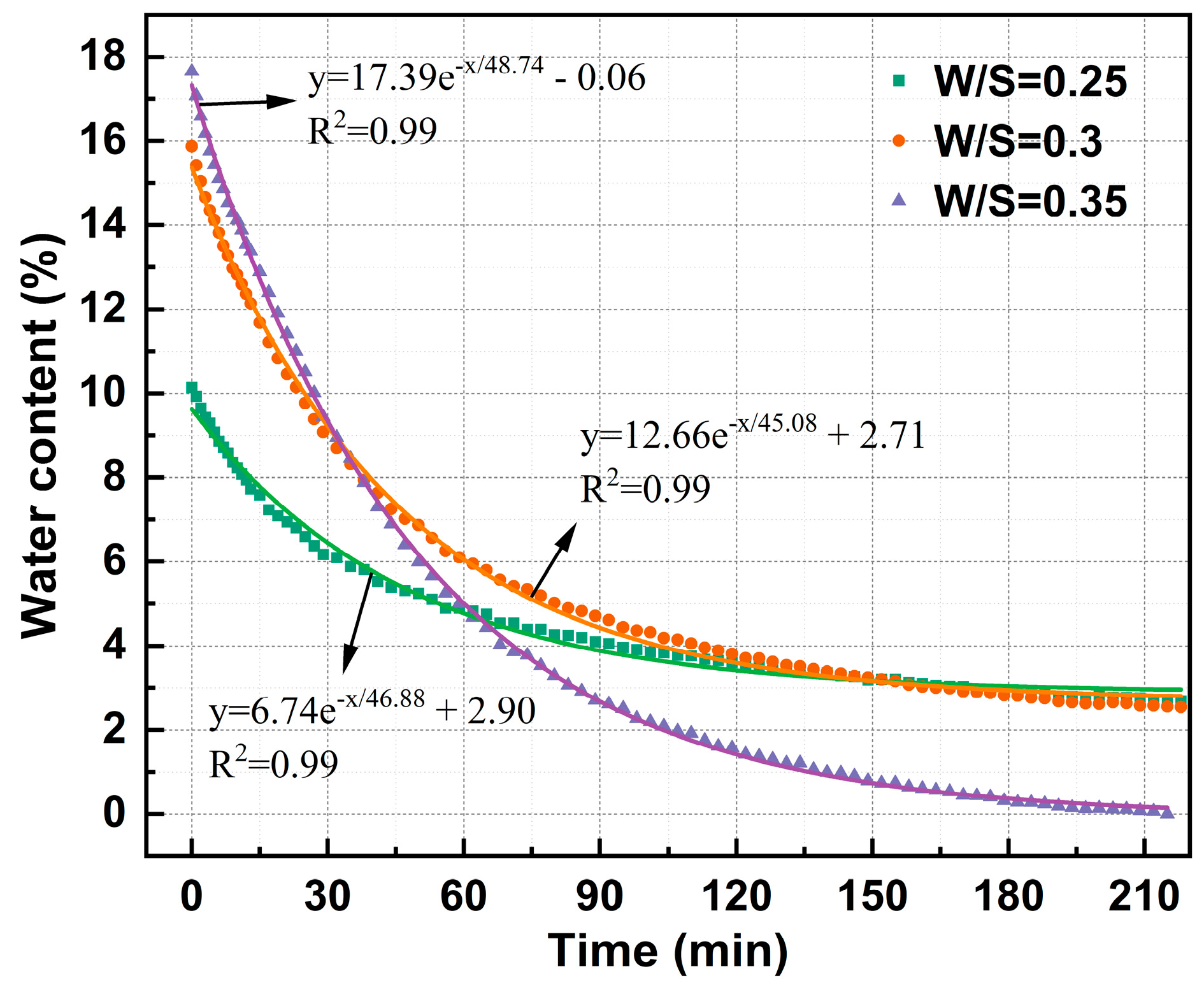
3.1. Regulation of Water Content Regulation
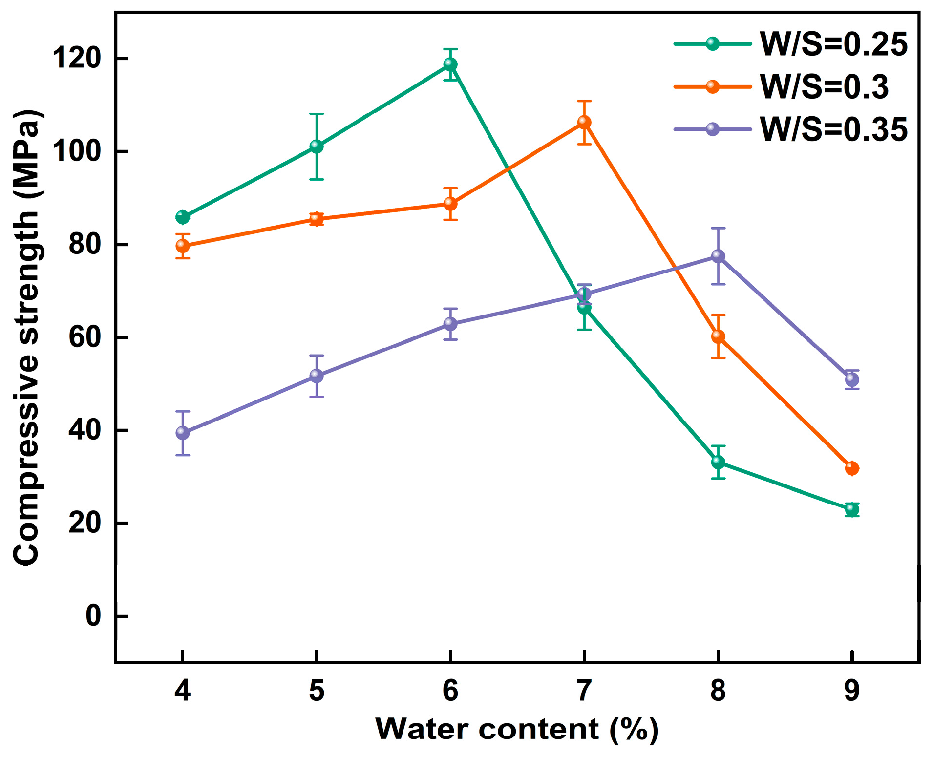
3.2. Compressive Strength
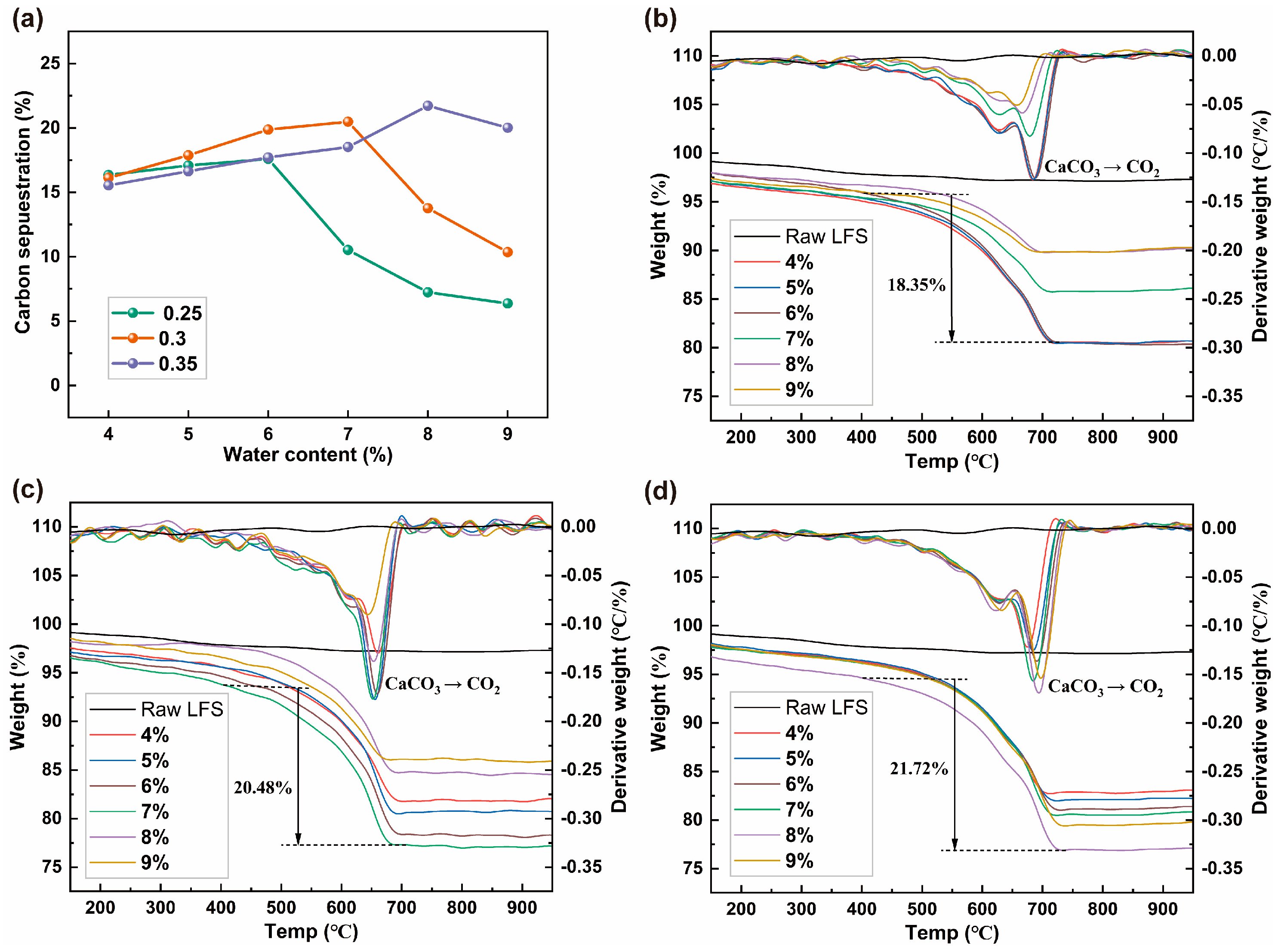
3.3. Carbon Sequestration
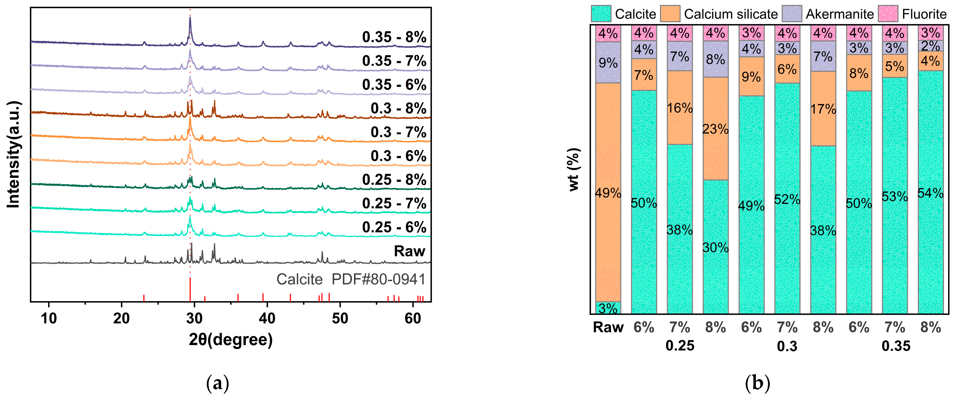
3.4. Mineralogical Compositions
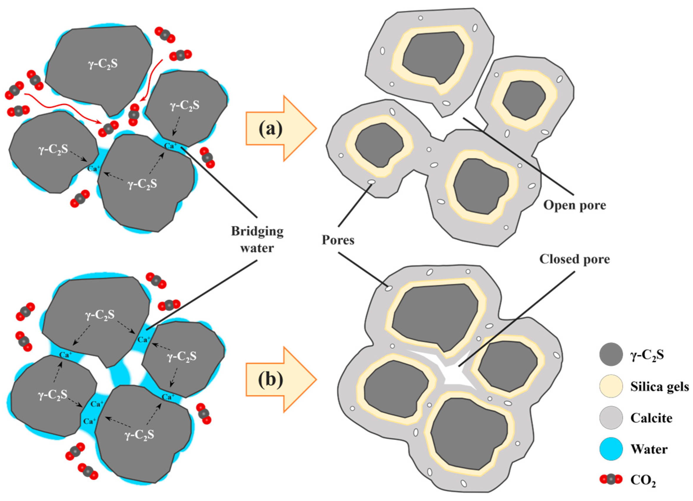
3.5. Morphology
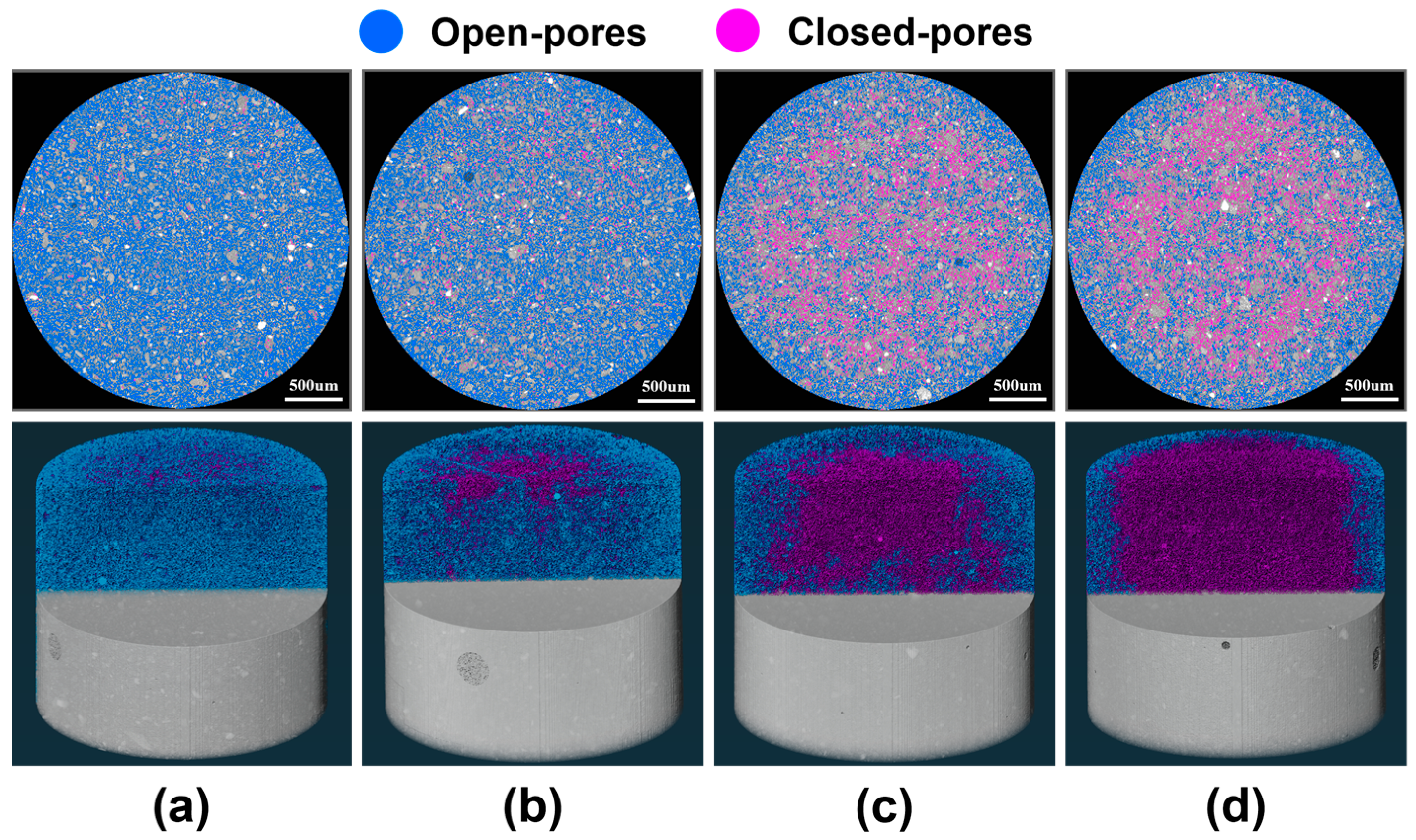
3.6. Pore Structure
4. Discussion
5. Limitations and Future Directions
6. Conclusions
- A method was developed to control the water content of steel slag specimens, and the significant influence of moisture and pore space on the carbonation reaction of steel slag specimens was innovatively identified. The carbonation process relies on pores for CO2 diffusion and also requires a certain level of moisture for Ca2+ dissolution and diffusion. Increasing the water content enhances particle cementation and carbonation capacity in steel slag specimens; however, excessive water hinders CO2 diffusion. Reducing the water content can increase the carbonation depth but may compromise gelling and carbon sequestration ability. Therefore, achieving a balance is crucial in controlling the water content;
- The pour-molding process was employed to enhance the porosity of steel slag specimens. The increase in pores reduces the density of the steel slag specimens but enhances their CO2 diffusion capacity. This is different from the common compression-molding process, achieving the absorption and fixation of approximately 217.2 kg of CO2 for each ton of LFS at a 0.35 water–solid ratio and optimum water content. This carbon sequestration capacity is at an industry-leading level;
- An innovative three-dimensional pore structure analysis method was used to analyze the connected and closed holes, and it was found that steel slag particles with low water content have a minimal impact on pore connectivity during cementation, allowing most of the pores to remain open. Conversely, steel slag particles with higher water content result in the formation of more closed pores that hinder CO2 diffusion into the interior of the steel slag specimens, leading to a lower degree of carbonation compared to their surfaces. This study reveals the key mechanisms by which pore space and moisture affect carbonation reactions.
Author Contributions
Funding
Data Availability Statement
Conflicts of Interest
References
- Xu, Y.; Lv, Y.; Qian, C. Comprehensive multiphase visualization of steel slag and related research in cement: Detection technology and application. Constr. Build. Mater. 2023, 386, 131572. [Google Scholar] [CrossRef]
- Yu, X.; Chu, J.; Wu, S.; Wang, K. Production of biocement using steel slag. Constr. Build. Mater. 2023, 383, 131365. [Google Scholar] [CrossRef]
- Xu, M.; Zhang, Y.; Yang, S.; Mo, L.; Liu, P. Effects of internal CO2 curing provided by biochar on the carbonation and properties of steel slag-based artificial lightweight aggregates (SALAs). Cem. Concr. Compos. 2023, 142, 105197. [Google Scholar] [CrossRef]
- Zhang, Y.; Yu, L.; Cui, K.; Wang, H.; Fu, T. Carbon capture and storage technology by steel-making slags: Recent progress and future challenges. Chem. Eng. J. 2023, 455, 140552. [Google Scholar] [CrossRef]
- Gao, W.; Zhou, W.; Lyu, X.; Liu, X.; Su, H.; Li, C.; Wang, H. Comprehensive utilization of steel slag: A review. Powder Technol. 2023, 422, 118449. [Google Scholar] [CrossRef]
- Song, Q.; Guo, M.Z.; Wang, L.; Ling, T.C. Use of steel slag as sustainable construction materials: A review of accelerated carbonation treatment. Resour. Conserv. Recycl. 2021, 173, 105740. [Google Scholar] [CrossRef]
- Rui, Y.; Qian, C. CO2-fixing steel slag on hydration characteristics of cement-based materials. Constr. Build. Mater. 2022, 354, 129193. [Google Scholar] [CrossRef]
- Shen, J.; Zhang, Q.; Xu, L.; Tian, S.; Wang, P. Future CO2 emission trends and radical decarbonization path of iron and steel industry in China. J. Clean Prod. 2021, 326, 129354. [Google Scholar] [CrossRef]
- Yang, Y.; Xu, W.; Wang, Y.; Shen, J.; Wang, Y.; Geng, Z.; Wang, Q.; Zhu, T. Progress of CCUS technology in the iron and steel industry and the suggestion of the integrated application schemes for China. Chem. Eng. J. 2022, 450, 138438. [Google Scholar] [CrossRef]
- Pan, S.Y.; Adhikari, R.; Chen, Y.H.; Li, P.; Chiang, P.C. Integrated and innovative steel slag utilization for iron reclamation, green material production and CO2 fixation via accelerated carbonation. J. Clean Prod. 2016, 137, 617–631. [Google Scholar] [CrossRef]
- Yadav, S.; Mehra, A. Experimental study of dissolution of minerals and CO2 sequestration in steel slag. Waste Manage. 2017, 64, 348–357. [Google Scholar] [CrossRef] [PubMed]
- Espinosa, A.B.; López-Ausín, V.; Fiol, F.; Serrano-López, R.; Ortega-López, V. Analysis of the deformational behavior of a clayey foundation soil stabilized with ladle furnace slag (LFS) using a finite element software. Mater. Today Proc. 2023, in press. [Google Scholar] [CrossRef]
- Pan, S.Y.; Chang, E.E.; Chiang, P.C. CO2 capture by accelerated carbonation of alkaline wastes: A review on its principles and applications. Aerosol Air Qual. Res. 2012, 12, 770–791. [Google Scholar] [CrossRef]
- Mo, L.; Zhang, F.; Deng, M. Mechanical performance and microstructure of the calcium carbonate binders produced by carbonating steel slag paste under CO2 curing. Cem. Concr. Res. 2016, 88, 217–226. [Google Scholar] [CrossRef]
- Li, L.; Jiang, Y.; Pan, S.Y.; Ling, T.C. Comparative life cycle assessment to maximize CO2 sequestration of steel slag products. Constr. Build. Mater. 2021, 298, 123876. [Google Scholar] [CrossRef]
- Humbert, P.S.; Castro-Gomes, J.P.; Savastano, H., Jr. Clinker-free CO2 cured steel slag based binder: Optimal conditions and potential applications. Constr. Build. Mater. 2019, 210, 413–421. [Google Scholar] [CrossRef]
- Ghouleh, Z.; Guthrie, R.I.; Shao, Y. High-strength KOBM steel slag binder activated by carbonation. Constr. Build. Mater. 2015, 99, 175–183. [Google Scholar] [CrossRef]
- Zhu, F.; Cui, L.; Liu, Y.; Zou, L.; Hou, J.; Li, C.; Wu, G.; Xu, R.; Jiang, B.; Wang, Z. Experimental Investigation and Mechanism Analysis of Direct Aqueous Mineral Carbonation Using Steel Slag. Sustainability 2023, 16, 81. [Google Scholar] [CrossRef]
- Wang, Y.; Liu, J.; Hu, X.; Chang, J.; Zhang, T.; Shi, C. Utilization of accelerated carbonation to enhance the application of steel slag: A review. J. Sustain. Cen.-Based Mater. 2023, 12, 471–486. [Google Scholar] [CrossRef]
- Liu, J.; Liu, G.; Zhang, W.; Li, Z.; Jin, H.; Xing, F. A new approach to CO2 capture and sequestration: A novel carbon capture artificial aggregates made from biochar and municipal waste incineration bottom ash. Constr. Build. Mater. 2023, 398, 132472. [Google Scholar] [CrossRef]
- Zhong, X.; Li, L.; Jiang, Y.; Ling, T.C. Elucidating the dominant and interaction effects of temperature, CO2 pressure and carbonation time in carbonating steel slag blocks. Constr. Build. Mater. 2021, 302, 124158. [Google Scholar] [CrossRef]
- Luo, Z.; Wang, Y.; Yang, G.; Ye, J.; Zhang, W.; Liu, Z.; Mu, Y. Effect of curing temperature on carbonation behavior of steel slag compacts. Constr. Build. Mater. 2021, 291, 123369. [Google Scholar] [CrossRef]
- Zhang, S.; Ghouleh, Z.; Mucci, A.; Bahn, O.; Provençal, R.; Shao, Y. Production of cleaner high-strength cementing material using steel slag under elevated-temperature carbonation. J. Clean Prod. 2022, 342, 130948. [Google Scholar] [CrossRef]
- Zhang, S.; Ghouleh, Z.; Liu, J.; Shao, Y. Converting ladle slag into high-strength cementing material by flue gas carbonation at different temperatures. Resour. Conserv. Recycl. 2021, 174, 105819. [Google Scholar] [CrossRef]
- Li, J.; Ni, W.; Wang, X.; Zhu, S.; Wei, X.; Jiang, F.; Zeng, H.; Hitch, M. Mechanical activation of medium basicity steel slag under dry condition for carbonation curing. J. Build. Eng. 2022, 50, 104123. [Google Scholar] [CrossRef]
- Ukwattage, N.L.; Ranjith, P.G.; Li, X. Steel-making slag for mineral sequestration of carbon dioxide by accelerated carbonation. Measurement 2017, 97, 15–22. [Google Scholar] [CrossRef]
- Zhang, X.; Su, Y.; Liu, S. The effect of carbonation pressure on microbial assisted steel slag-based carbon sequestration material. J. Build. Eng. 2024, 86, 108974. [Google Scholar] [CrossRef]
- Tian, S.; Jiang, J.; Chen, X.; Yan, F.; Li, K. Direct Gas-Solid Carbonation Kinetics of Steel Slag and the Contribution to Insitu Sequestration of Flue Gas CO2 in Steel-Making Plants. ChemSusChem 2013, 6, 2348–2355. [Google Scholar] [CrossRef]
- Nielsen, P.; Boone, M.A.; Horckmans, L.; Snellings, R.; Quaghebeur, M. Accelerated carbonation of steel slag monoliths at low CO2 pressure–microstructure and strength development. J. CO2 Util. 2020, 36, 124–134. [Google Scholar] [CrossRef]
- Tang, P.; Xuan, D.; Cheng, H.W.; Poon, C.S.; Tsang, D.C. Use of CO2 curing to enhance the properties of cold bonded lightweight aggregates (CBLAs) produced with concrete slurry waste (CSW) and fine incineration bottom ash (IBA). J. Hazard. Mater. 2020, 381, 120951. [Google Scholar] [CrossRef]
- Jiang, Y.; Ling, T.C. Production of artificial aggregates from steel-making slag: Influences of accelerated carbonation during granulation and/or post-curing. J. CO2 Util. 2020, 36, 135–144. [Google Scholar] [CrossRef]
- GB/T 17671-2021; Test Method of Cement Mortar Strength (ISO Method). State Administration of Market Supervision and Standardization Administration: Beijing, China, 2021. (In Chinese)
- McCarter, W.J.; Chrisp, T.M.; Starrs, G.; Owens, E.H. Setting, hardening and moisture-loss within a cement-based backfill grout under simulated repository environments. Measurement 2012, 45, 235–242. [Google Scholar] [CrossRef]
- Tan, Y.; Liu, Z.; Wang, F. Effect of temperature on the carbonation behavior of γ-C2S compacts. Cem. Concr. Compos. 2022, 133, 104652. [Google Scholar] [CrossRef]
- Yu, C.; Cui, C.; Zhao, J.; Liu, F.; Fu, S.; Li, G. Enhancing mechanical properties of dredged sludge through carbonation stabilization employing steel slag: An eco-friendly and cost-effective approach. Constr. Build. Mater. 2024, 412, 134748. [Google Scholar] [CrossRef]
- Wang, D.; Xiao, J.; Duan, Z. Strategies to accelerate CO2 sequestration of cement-based materials and their application prospects. Constr. Build. Mater. 2022, 314, 125646. [Google Scholar] [CrossRef]
- Mu, Y.; Liu, Z.; Wang, F. Comparative study on the carbonation-activated calcium silicates as sustainable binders: Reactivity, mechanical performance, and microstructure. ACS Sustain. Chem. Eng. 2019, 7, 7058–7070. [Google Scholar] [CrossRef]
- Humbert, P.S.; Castro-Gomes, J. CO2 activated steel slag-based materials: A review. J. Clean Prod. 2019, 208, 448–457. [Google Scholar] [CrossRef]
- Wray, J.L.; Daniels, F. Precipitation of calcite and aragonite. J. Am. Chem. Soc. 1957, 79, 2031–2034. [Google Scholar] [CrossRef]
- Guan, X.; Liu, S.; Feng, C.; Qiu, M. The hardening behavior of γ-C2S binder using accelerated carbonation. Constr. Build. Mater. 2016, 114, 204–207. [Google Scholar] [CrossRef]
- Moon, E.J.; Choi, Y.C. Development of carbon-capture binder using stainless steel argon oxygen decarburization slag activated by carbonation. J. Clean Prod. 2018, 180, 642–654. [Google Scholar] [CrossRef]
- Ren, E.; Tang, S.; Liu, C.; Yue, H.; Li, C.; Liang, B. Carbon dioxide mineralization for the disposition of blast-furnace slag: Reaction intensification using NaCl solutions. Greenh. Gases 2020, 10, 436–448. [Google Scholar] [CrossRef]
- Kim, J.; Azimi, G. The CO2 sequestration by supercritical carbonation of electric arc furnace slag. J. CO2 Util. 2021, 52, 101667. [Google Scholar] [CrossRef]


| Oxides | CaO | SiO2 | Cr2O3 | MgO | TiO2 | Fe2O3 | Others |
|---|---|---|---|---|---|---|---|
| LFS | 71.23 | 21.31 | 2.37 | 1.96 | 1.72 | 1.27 | 0.12 |
| Samples | Water Content | Total Porosity | Open Porosity | Closed Porosity |
|---|---|---|---|---|
| a | uncarbonated | 20.44% | 20.18% | 0.26% |
| b | 6% | 17.69% | 16.90% | 0.79% |
| c | 7% | 10.60% | 7.14% | 3.46% |
| d | 8% | 13.61% | 8.52% | 5.09% |
Disclaimer/Publisher’s Note: The statements, opinions and data contained in all publications are solely those of the individual author(s) and contributor(s) and not of MDPI and/or the editor(s). MDPI and/or the editor(s) disclaim responsibility for any injury to people or property resulting from any ideas, methods, instructions or products referred to in the content. |
© 2024 by the authors. Licensee MDPI, Basel, Switzerland. This article is an open access article distributed under the terms and conditions of the Creative Commons Attribution (CC BY) license (https://creativecommons.org/licenses/by/4.0/).
Share and Cite
Lin, S.; Chen, P.; Xiang, W.; Hu, C.; Li, F.; Liu, J.; Ding, Y. Exploring the Effect of Moisture on CO2 Diffusion and Particle Cementation in Carbonated Steel Slag. Appl. Sci. 2024, 14, 3631. https://0-doi-org.brum.beds.ac.uk/10.3390/app14093631
Lin S, Chen P, Xiang W, Hu C, Li F, Liu J, Ding Y. Exploring the Effect of Moisture on CO2 Diffusion and Particle Cementation in Carbonated Steel Slag. Applied Sciences. 2024; 14(9):3631. https://0-doi-org.brum.beds.ac.uk/10.3390/app14093631
Chicago/Turabian StyleLin, Shenqiu, Ping Chen, Weiheng Xiang, Cheng Hu, Fangbin Li, Jun Liu, and Yu Ding. 2024. "Exploring the Effect of Moisture on CO2 Diffusion and Particle Cementation in Carbonated Steel Slag" Applied Sciences 14, no. 9: 3631. https://0-doi-org.brum.beds.ac.uk/10.3390/app14093631