
Conjugate Heat Transfer Advancements and Applications in Aerospace Engine Technology

1
China Aerodynamics Research and Development Center, Computational Aerodynamics Institute, Mianyang 621000, China
2
China Aerodynamics Research and Development Center, Mianyang 621000, China
*
Author to whom correspondence should be addressed.
Appl. Sci. 2024, 14(9), 3556; https://0-doi-org.brum.beds.ac.uk/10.3390/app14093556
Submission received: 27 March 2024
/
Revised: 20 April 2024
/
Accepted: 21 April 2024
/
Published: 23 April 2024
(This article belongs to the Topic Advanced Heat and Mass Transfer Technologies)
Abstract
:Featured Application
Provide support for temperature prediction of metal components affected by fluid–thermal coupling, such as turbines and exhaust nozzles.
Abstract
Over the past few decades, conjugate heat transfer (CHT) technology has been instrumental in predicting temperature fields within aerospace engines, guiding engine design with its predictive capabilities. This paper comprehensively surveys the foundational technologies of CHT and their applications in engine design, backed by an extensive literature review. A novel coupling iteration methodology, su-F-TFTB, was proposed. Following this, it introduced grid splicing technology tailored for heat flux conservation, which significantly enhances the adaptability of CHT grids. Ultimately, this study employed the self-developed Aerospace Engine Numerical Simulation (AENS v4.0.1) software to perform CHT analyses on NASA-C3X turbine blades equipped with ten radial cooling systems. A comparative analysis of pressure distributions across various density meshes was undertaken to affirm mesh independence. Furthermore, the impacts of the Spalart–Allmaras (SA) one-equation model and k–ω Shear Stress Transport (SST) two-equation model on the temperature distribution in conjugate heat transfer were investigated. The results indicated that the k–ω SST model exhibited superior performance, aligning closely with NASA experimental data. This validation confirmed the effectiveness of the software.
1. Introduction
Advancements in aviation technology have resulted in a substantial increase in the inlet temperatures of next-generation aero-engine high-pressure turbines, which now range between 2100 K and 2200 K and continue to climb. These temperatures significantly surpass the melting points of current high-performance turbine blade materials, posing significant challenges to the longevity and safety of these components.
To achieve more accurate predictions of the temperature distribution closer to experimentally obtained values of gas turbine blades, one must concentrate on conjugating the boundary condition at the fluid–solid interface through coupled heat transfer analysis. Such a coupled field study is termed as conjugate heat transfer (CHT) [1].
Over the past decade, conjugate heat transfer has emerged as a pivotal tool for elucidating the thermal exchange mechanisms within air-cooled turbines. Pioneering work by Bohn et al. [2] harnessed this method to simulate the low-temperature air cooling of Mark II blades, which featured ten cylindrical cooling passages. Their findings revealed a commendable concordance with empirical observations, validating the efficacy of their computational approach. Expanding upon this foundation, Bohn et al. [3] leveraged the same computational paradigm to scrutinize the thermodynamic performance of a singular cooling cavity proximate to the blade tip, alongside a pair of slit ejectors situated along the leading-edge stagnation line of a film-cooled guide vane.
Heidmann et al. [4] undertook an exhaustive comparative analysis, juxtaposing the cooling efficacy of turbine blades crafted from high-conductivity superalloys against those composed of lower-conductivity ceramics. Their investigations underscored the intricate interplay between material thermal properties and heat dissipation strategies and poignantly illustrated the convoluted nature of heat transfer within solid structures during the film cooling of turbine blades, highlighting the profound impact of film coverage on thermal transport dynamics.
Complementing these studies, Facchini et al. [5] conducted a meticulous numerical examination of both conjugate and non-conjugate heat transfer phenomena within NASA-C3X planar cascades. Their research was primarily centered on delineating the influence of phase transitions on heat transfer processes. In parallel, Montomoli et al. [6,7] executed a sophisticated conjugate heat transfer simulation within the transonic regime of the MT1 HP stage, yielding results that exhibited a striking alignment with empirical data.
Most recently, Zheng et al. [8] have advanced the state-of-the-art by integrating experimental data with a sophisticated conjugate heat transfer model to predict the spatial distribution of blade temperature, static pressure, and convective heat transfer coefficients for a NASA-C3X turbine blade adorned with ten cylindrical cooling channels. Their work encompassed simulations under five distinct turbulence models, culminating in a comprehensive comparison with empirical findings. This combination of computational modeling and empirical validation represents a significant stride forward in our understanding of the thermal management within advanced turbine systems.
Scholl et al. [9] employed Large Eddy Simulations (LESs) to investigate the internal cooling channels of a turbine blade at a Reynolds number of 40,000 and a blockage ratio of 0.3. Their findings highlighted the critical role of thermal boundary conditions in augmenting heat transfer within the channel. Local simulations indicated that transitioning from a decoupled condition to a coupled thermal condition markedly alters the heat transfer outcomes, culminating in a variation of up to 80%. Notably, the enhancement factor exceeds 50% in regions behind the turbulator, where a substantial recirculation zone amplifies the heat transfer efficacy. Consequently, for an accurate assessment of the heat transfer enhancement on the blade walls, conjugate heat transfer computations are imperative.
The aim of this paper is to devise a CHT solver based on Aerospace Engine Numerical Simulation (AENS) software, thereby facilitating enhanced efficiency and practicality for engineers engaged in the design and development of aviation engines. Initially, this paper delves into the realm of coupling iteration technology, meticulously examining its evolution and proposing novel coupling iteration methodologies. Following this, it introduces grid splicing technology tailored for heat flux conservation, which significantly enhances the adaptability of CHT grids. Ultimately, the program’s efficacy is substantiated through simulations utilizing NASA-C3X turbine cascades featuring internal cooling channels.
2. Numerical Method of Conjugate Heat Transfer
2.1. Coupled Technique for Conjugate Heat Transfer
In the realm of coupled field analysis, there exist two distinct methodological paradigms: the monolithic approach [10,11,12,13] and the partitioned approach [6,14,15]. The monolithic approach amalgamates the fluid and solid domains into a unified system of equations that are addressed concurrently, sharing a singular computational infrastructure.
Conversely, partitioned methods decompose the problem into separate fluid and solid regions that are calculated independently, with the domains connected via an exchange of physical quantities at the coupled boundaries. Within the partitioned coupling framework, a variety of computational techniques can be selectively implemented, including finite difference, finite volume, boundary element, and finite element methods, affording greater computational versatility.
The partitioned approach has garnered significant attention from a myriad of investigators [16,17,18]. It partitions the problem into two subdomains, each governed by a separate solver, simulating the fluid and solid regions separately. This strategy allows for the seamless integration of existing fluid flow or heat conduction solvers into a comprehensive conjugate heat transfer solver without imposing significant alterations upon the original computational program.
In this partitioning strategy, the exchange of information between the fluid and solid subdomains becomes pivotal. The conventional serial staggered (CSS) method, often employed in the partitioned approach, serves as a typical example. Here, physical quantities are exchanged post-convergence of flow and heat transfer in each subdomain, a technique colloquially referred to as explicit coupling technology. As depicted in Figure 1, Crowell et al. [19] utilized the CSS algorithm in their aero-thermal coupling study. The CSS scheme is straightforward to implement, and there are no modifications at the solver level for flow and heat transfer, which each iterate independently.
The schematics in the upper portion of Figure 2 depict the procedural flowcharts for two distinct methods: Flux Forward Temperature Back (FFTB) and Temperature Forward Flux Back (TFFB). Both methodologies commence with an estimated coupled wall temperature, which is adopted as the preliminary boundary condition. Although this strategy expedites the rate of iterative convergence, it introduces marked fluctuations in the fluid’s physical parameters with each iteration, potentially compromising the coupled system’s stability. Within the heat transfer coefficient Forward Temperature Back (hFTB) methodology, the solid side’s revised boundary conditions precipitate a corresponding adjustment in the resultant wall temperature, which is then relayed to the fluid domain. Empirical evidence has indicated that the stability of this triad of methods hinges on the attainment of a consistent and unique solution at the onset of the computational loop. Moreover, it has been observed that incorporating the wall temperature as the initial boundary condition during the iterative process can undermine the coupling’s stability, particularly as the frequency of fluid iterations diminishes.
Conversely, implementing heat flux as the boundary condition enhances stability. In light of these findings, Scholl et al. [15] introduced the heat transfer coefficient Forward Flux Back (hFFB) method as an innovative alternative. This methodology imposes heat flow boundary conditions on the fluid domain, leading to a demonstrably stable and more rapid convergence in comparison to its predecessors.
In recent years, the integration of CHT into these unsteady simulations presents a significant challenge. This is attributable to the necessity for exceedingly small-time steps to accurately capture the gas flow dynamics, particularly in scenarios involving turbine blades. He and Oldfield’s seminal work [20] highlights the substantial disparity in time scales between solid conduction and fluid convection within the context of turbine blade heat transfer. They emphasized that this ratio can vary between 105 and 109, indicating an enormous temporal gap between the two phenomena. This discrepancy poses a formidable obstacle, as it necessitates a commensurate increase in computational resources to adequately resolve the transient behavior of both the fluid and solid domains.
In addressing the concerns related to temporal precision, certain researchers have advocated for the redistribution of physical parameters within each iterative time increment t + Δt to enhance the time resolution of CSS methodologies [21,22]. Nonetheless, Alonso [23] cautioned that marked disparities in time scales impose limitations on the frequency of data interchange across distinct physical domains, and these maneuvers may correspondingly amplify computational workloads.
In response to this challenge, Crowell introduced an augmented version of the CSS algorithm, termed the Implicitly Split Scheme (ISS) [24]. This adaptation was then implemented within the context of shockwave–boundary layer interactions within supersonic wind tunnels, as depicted in Figure 3.
In certain transient conjugate heat transfer analyses characterized by prolonged periods, the quasi-steady state approximation becomes applicable [25,26,27,28]. Stefan Voigt et al. [29] proposed an alternative quasi-steady-state technique termed the uFFTB method, which is depicted in Figure 4. Iterative coupling between the fluid and solid domains, achieved through independent computations within each domain until convergence, enhances computational efficiency while ensuring conservation of heat flux.
Oh et al. [30] artificially increased the solid thermal diffusivity and compared it to the actual physical diffusivity as a strategy to mitigate the substantial time scale discrepancies between the fluid and solid zones. Shi et al. [31] introduced a time scale control model that is dependent on the Biot number (Bi) and Fourier number (Fo), drawing upon the principles of the similarity theory. This model manipulates the density and thermal conductivity of solids through the application of the similarity theory, thereby achieving time scale control over transient heat conduction.
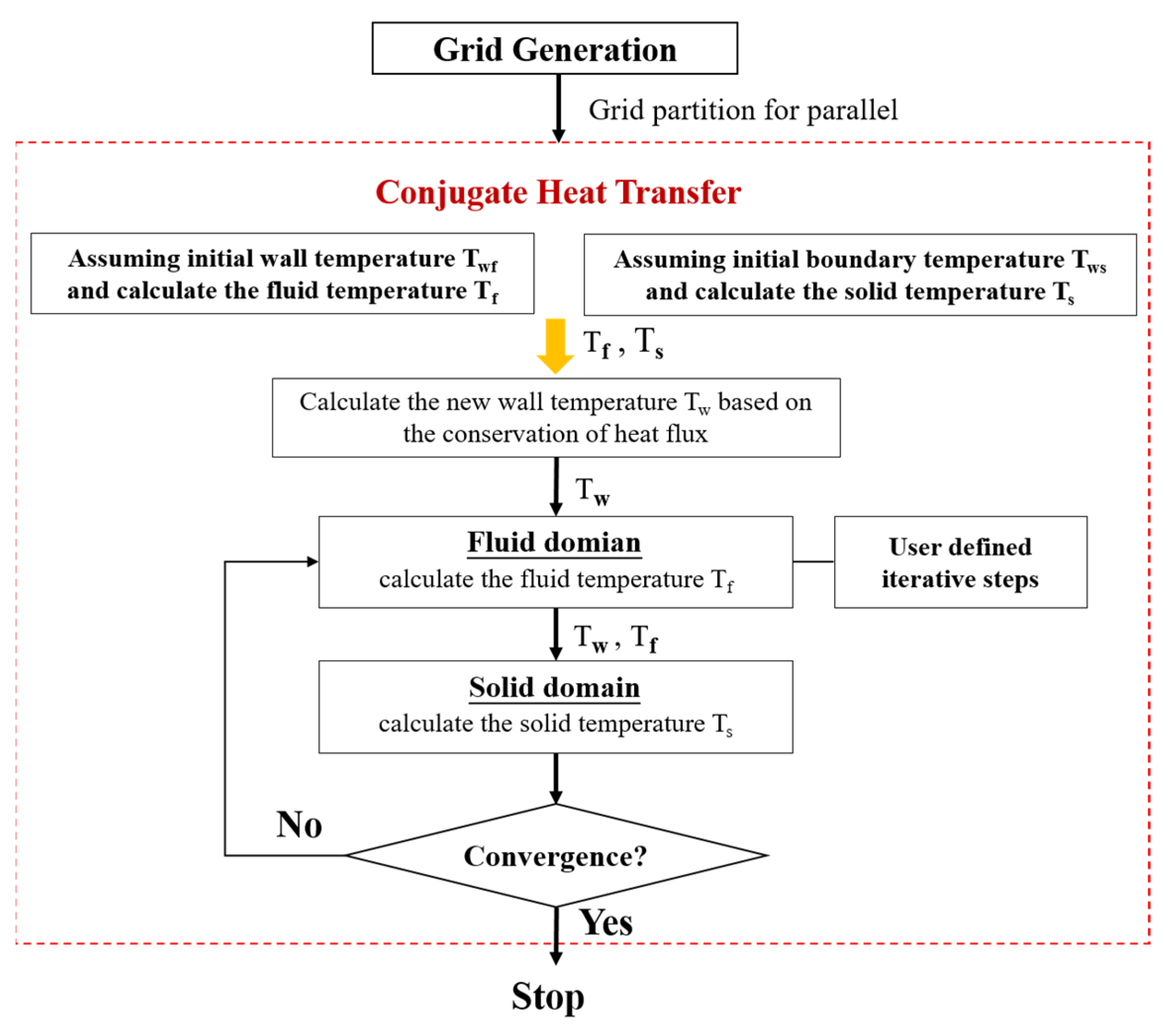
In this paper, we propose the steady-unsteady Flux to Temperature Forward and Temperature Back (su-F-TFTB) coupling framework based on the CSS strategy and uFFTB approach to guarantee the conservation of heat flux in fluid–structure interactions, considering both steady-state and transient problems with flexibility. Initially, the fluid and structural temperature distributions are calculated using the assumed initial fields for both domains. Subsequently, the level of heat flux is determined from the temperature gradient at the boundary, ensuring the strict conservation of heat flux between the fluid and solid meshes. The node temperatures are then updated for the transfer of physical quantities. During the calculation of the thermal field within each fluid or solid region, the iteration steps of the respective solvers are extracted outside the loop and treated as controllable parameters. This enables independent control over the post-computation steps for performing conservation interpolation in both the fluid and structural subdomains.
2.2. Mesh Adaptability in Conjugate Heat Transfer
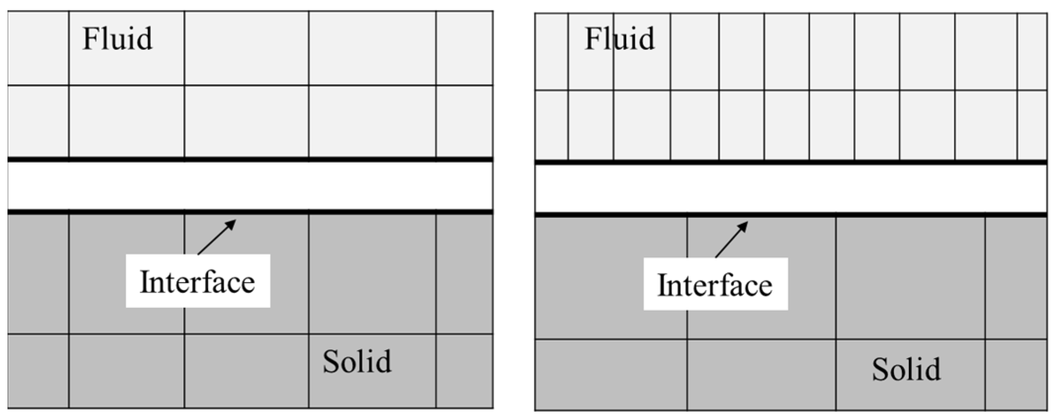
Within the realm of partitioned techniques for conveying conjugate heat transfer in air-cooled turbines, a plethora of investigations [32,33,34,35] have adopted a fully conformal meshing strategy, ensuring an exact correspondence between the fluid and solid nodes at the fluid–solid interface, as depicted in Figure 5. Nevertheless, in tackling the complexities inherent to large-scale engineering challenges, it is commonplace to encounter considerable discrepancies in the topology and resolution of grids across different media domains, as exemplified in Figure 6. One of the intrinsic challenges of conjugate heat transfer simulations lies in the necessity for a meticulous alignment of boundary points along the solid–fluid interface [36], which imposes stringent constraints on the preservation of boundary heat flux in engineering applications that necessitate such simulations. Consequently, the development of a data interpolation methodology that upholds conservation principles across non-conforming grids emerges as a pivotal consideration for the successful implementation of conjugate heat transfer simulations within extensive engineering frameworks.
The transfer of heat flux at the interface necessitates that conservation be guaranteed, and for the entire interface, the overall conservation is satisfied:
where S refers to the entire interface; Fs and Ff refer to the flux on the solid and fluid sides, respectively.
Regarding fluid–fluid and fluid–solid interfaces, congruent grids facilitate robust flux transfer and uphold the principle of flux conservation. For mismatched grids, the patched grid algorithm of the conservation class is used to implement data interpolation [38]. Farrell et al. [39] pioneered the “local supermesh” approach, grounded in the concept of element intersection, and effectively integrated a sophisticated 3D element intersection algorithm [40] into an unstructured mesh framework. Subsequent research endeavors [41,42] have further expanded on this technique, advancing both two-dimensional and three-dimensional hybrid grid cutting capabilities. These advancements have been successfully applied to the intricate calculations involving overlapping grids within the flow field, yielding promising outcomes.
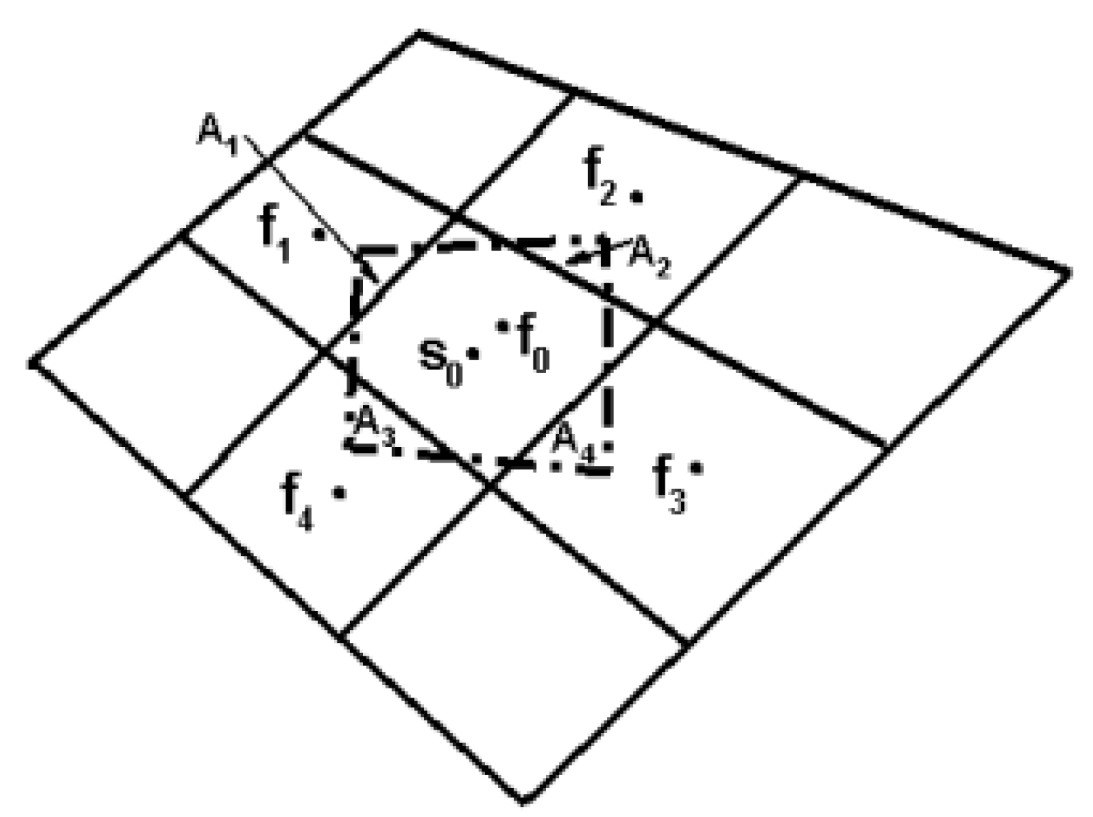
Building upon the concept of “local supermesh”, this paper extends its application to conjugate heat transfer calculations. By utilizing “local supermesh”, heat flux conservation is maintained across relatively flat interfaces. For coupling regions with significant curvature, the heat flux is decomposed along both the normal and tangential directions of the interface. The superposition of the heat flux vectors from multiple subdomains ensures the conservation of heat inflow and outflow. Illustrating this with the fluid–solid interface, Figure 7 depicts the discretized unpaired interface. Here, the continuous lines represent the fluid mesh, whereas the dashed lines denote the solid mesh. The conservation relationship of heat flux is shown as follows:
where fi designates a fluid element; s0 denotes a solid element; and Ai symbolizes the area of intersection between the fluid element fi and the solid element s0. The interpolation of the solid element’s flux is derived from that of the adjacent fluid element, with ci signifying the interpolation coefficient.
3. Case Study of Conjugate Heat Transfer
3.1. Specify Software AENS
The preceding chapters of this research culminate in the development of the AENS v4.0.1 software tool, which was specifically designed to facilitate fluid/structural/thermal multi-physics coupling within the core of an aero-engine. Central to this software is the harmonization of the fluid dynamics solver with the solid thermal solver, ensuring a seamless integration of the two disparate domains.
AENS software allows for the separate computation of fluid flow and structural heat conduction. In terms of inter-solver physical quantity access technology, AENS software employs data bus technology, which consolidates physical quantities from different solvers into a centralized data pool, enabling efficient mutual calling among all solvers. Within this software framework, the proposed su-F-TFTB coupling method and the “local overset grid”-based heat flux conservation interpolation method are developed and integrated, forming a simulation module suitable for CHT.
3.2. Computational Details
A brief description of the numerical technique is as follows:
- The spatial discretization is based on the finite volume cell vertex method for hybrid unstructured grids in the fluid domain.
- The Roe’s approximate method is used for the up-winding of convective fluxes.
- A slope limiter based on the Unstructured mesh Monotone Upstream-centered Schemes for Conservation Laws (U-MUSCL) reconstruction of the solution inside elements provides second-order discretization to maintain monotonicity.
- Turbulent viscous flows are represented by the conventional mass-averaged system of Navier–Stokes equations. Eddy viscosity is determined according to the k–ω Shear Stress Transport (SST) two-equation model.
- The spatial discretization method for solid domains adopts the finite element method.
- The steady thermal solver is adopted to heat conduction in the solid domain.
- The PETSC library is employed to iteratively solve both in the fluid and solid domains.
The methodology for addressing the conjugate heat transfer challenge begins with the segmentation of both the fluid and solid realms into discrete elements. To achieve this, we harness the capabilities of ANSYS ICEM 2021 R2 grid generation software, meticulously delineating the fluid and solid regions to ensure a precise representation of their respective physical attributes. In the fluid domain, a refined tetrahedral mesh is strategically deployed to encapsulate the central flow dynamics, complemented by structured prismatic elements along the solid boundaries. This configuration enhances the resolution within the viscous boundary layer, thereby augmenting the fidelity of the computational fluid dynamics (CFD) simulation. In contrast, the solid domain is uniformly meshed with tetrahedrons, extending throughout the entirety of the model to capture the intricate temperature gradients and thermal responses inherent to the material. The su-F-TFTB are succinctly encapsulated in Figure 8, providing a visual blueprint of the procedural workflow.
The solver employs a multi-block parallelization approach mirrored after that of the underlying CFD software, which markedly diminishes the aggregate computational burden. Leveraging the standard MPI (Message Passing Interface) protocol, the parallel solver ensures exceptional versatility across diverse computational platforms.
3.3. Flow Field over the C3X Vane
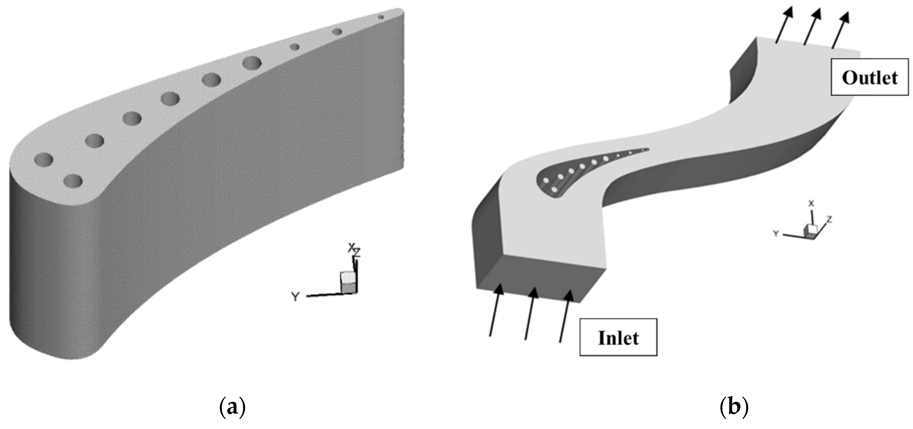
The blade investigated is the NASA-C3X turbine vane, for which empirical data were sourced from the study by Hylton et al. [44]. The schematic of the C3X vane, accessible to the public domain, is presented in Figure 9, serving as a visual reference for the geometric configuration under examination, where the axial chord length is 0.07816 m.
The NASA-C3X turbine vane is equipped with a strategic layout featuring ten radial cooling holes. The detailed configuration of these holes for the C3X vane is delineated in reference [44]. Leveraging the experimental specifications of this vane, a comprehensive computational model encompassing both the fluid dynamics and solid structures of the C3X vane has been devised, as depicted in Figure 10.
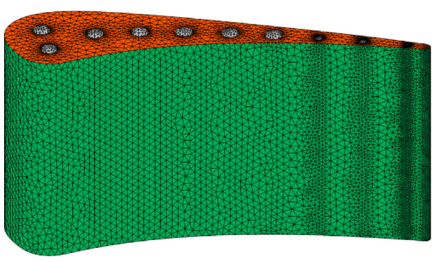
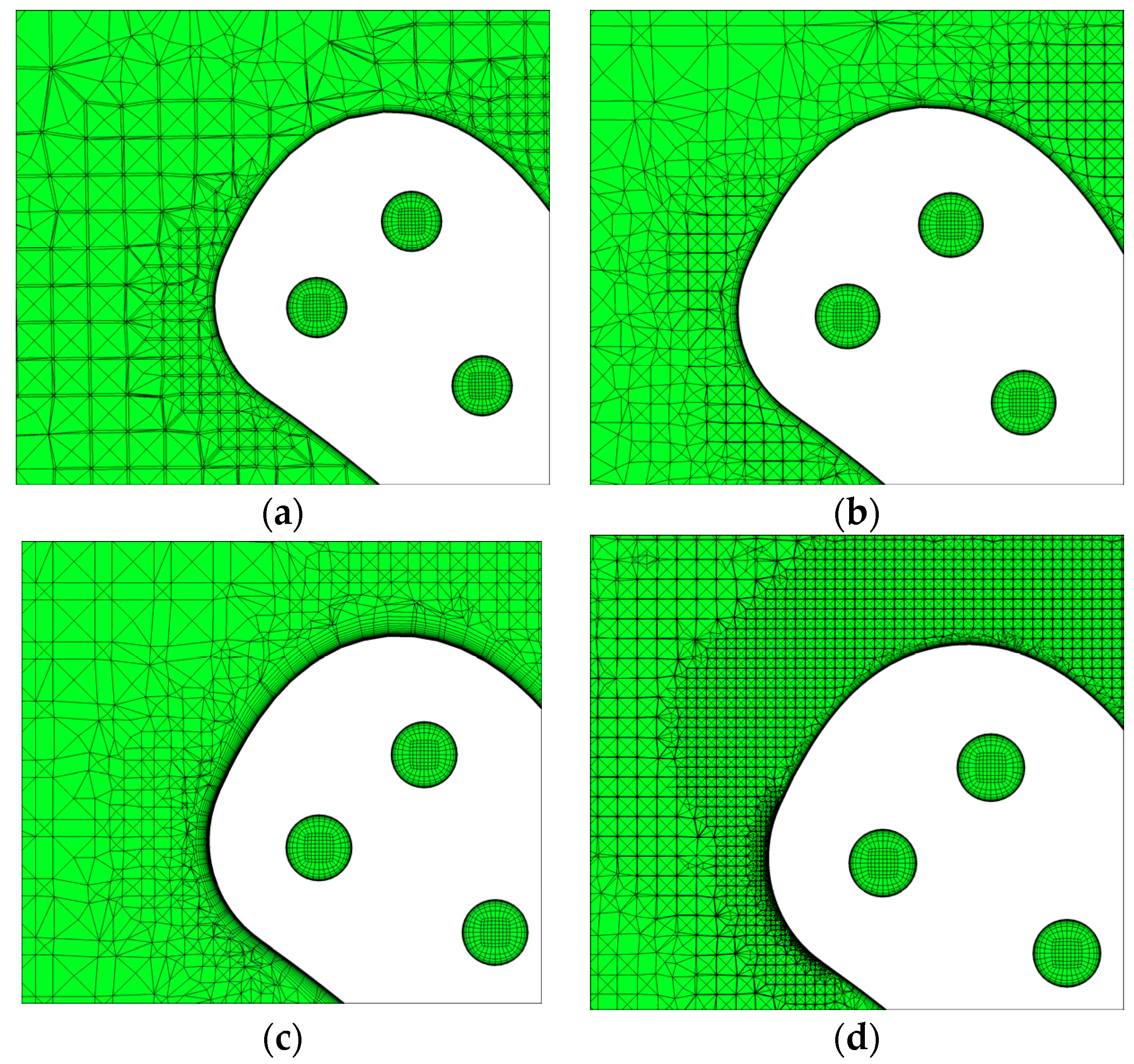
In order to validate mesh independence, four sets of fluid grids with varying densities and one set of solid grids were generated. The solid grid was composed entirely of unstructured tetrahedral elements. The fluid grid incorporated boundary layers at both the coupling surfaces and the fluid boundary walls, ensuring that the y+ < 1 of the first layer of cells had a growth rate of 1.2, resulting in an unstructured hybrid mesh configuration. For the fluid–solid coupling interface, it is not necessary for the grids to align; instead, a correspondence relationship is established during the computation based on the “supermesh” methodology. The mesh distribution of the solid domain is shown in Figure 11. Four sets of fluid meshes are shown in Figure 12. The overall computational time for the model with the maximum number of grids is approximately 50 h on Hygon C86 7185 processors.
In the fluid computational model, periodic boundary conditions are imposed to replicate the conditions within a single blade passage. At the inlet, the flow field is defined by the total temperature, total pressure, and the incoming flow velocity vector. Conversely, at the exit, an average static pressure boundary condition is prescribed, while all the other boundaries are presumed to behave as viscous walls. For thermophysical considerations, the model treats the working fluid as an ideal compressible gas, wherein the specific heat ratio γ varies, in a linear fashion, with temperature, adhering to the relationship γ = −7 × 10⁻⁵ × T + 1.4231, where T denotes the temperature in Kelvin. Furthermore, both the molecular viscosity μ and the thermal conductivity K of the fluid are articulated as temperature-dependent functions, utilizing the Sutherland’s formula, as encapsulated in Equations (3) and (4):
where μ0 = 1.7894 × 10⁻⁵ Pa·s; T0 = 273.11 K; λ0 = 0.0261 W/(m·K); and S = 110.56.
Fitting the specific heat capacity of gas Cp using a temperature polynomial:
where a0 = 957.110256; a1 = 0.2365234; a2 = 5.141 × 10⁻⁶; a3 = −3.39 × 10⁻⁹; and a4 = −6.09 × 10⁻¹².
The interface demarcating the external surfaces of the turbine blades and the inner walls of the cooling passages is classified as a coupled boundary, facilitating an integrated analysis of conjugate heat transfer. This technique allows for a precise depiction of the thermal interplay between the fluid and solid constituents, yielding a more authentic appraisal of the cooling efficacy afforded to the turbine blades. The fluid dynamics within the passages are addressed through the implementation of the k–ω SST turbulence model, which proficiently characterizes both the near-wall and free stream flow regimes. Simultaneously, the thermal response within the solid is computed via a steady-state heat conduction routine, ensuring that the energy transfer within the solid matrix is faithfully reproduced. It is pertinent to mention that while the fluid’s thermal conductivity is dynamically modulated in response to temporal temperature variations, the temperature within the solid is postulated to fluctuate marginally. Consequently, a simplification is adopted, whereby the thermal conductivity within the solid is treated as a constant for the duration of the simulation.
Calculations were performed under the auspices of operating condition Run-157 (Code-4521), with the requisite parameters for the flow field detailed in Table 1. All operating conditions and test results in this article are sourced from reference [44]. Correspondingly, Table 2 enumerates the material properties and operational parameters pertinent to the blade, whereas Table 3 delineates the inlet specifications for the internal cooling channel.
3.4. Results and Discussion
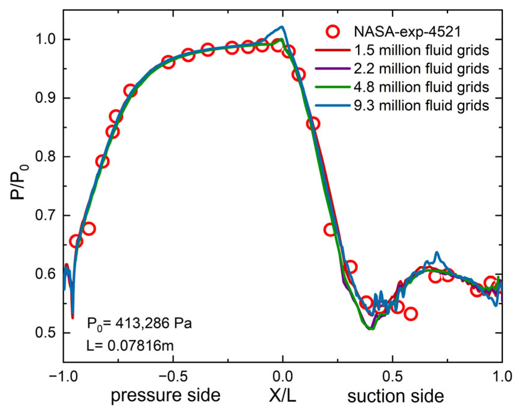
The comparison of the pressure distribution at mid-span across four different density flow field meshes with NASA experimental results reveals that the trend in pressure distribution for all four mesh densities closely aligns with the experimental data, as shown in Figure 13. The pressure drop along the surface is relatively gradual, with an increase in the rate of decrease observed near the trailing edge. On the suction surface, the pressure drops rapidly in the intake region, followed by a more gradual acceleration of the flow after the midsection (approximately p/p0 = 0.5–0.6). The calculation results exhibit a sharp rise in pressure at the leading-edge stagnation point, which may be attributed to the accumulation of flow due to an excessive lack of uniformity in the grid relative to the surrounding area at the stagnation point. Consequently, the largest pressure surge is observed in the finest mesh with 9.3 million cells. Beyond the midsection of the suction surface, pressure fluctuations occur, accompanied by an inverse pressure gradient, indicating the complexity of the flow characteristics in this region, which can lead to shockwave formation and separation phenomena. In areas of complex flow, denser meshes yield calculations that are closer to the experimental data, although overall discrepancies remain minor.
Figure 14 illustrates the average dimensionless pressure values at mid-span, revealing that as the mesh density increases, the calculated average pressure values converge towards the experimentally obtained mean pressures. Given this convergence, for the sake of accuracy in our numerical simulations, a mesh count of 9.3 million grids was selected for subsequent testing.
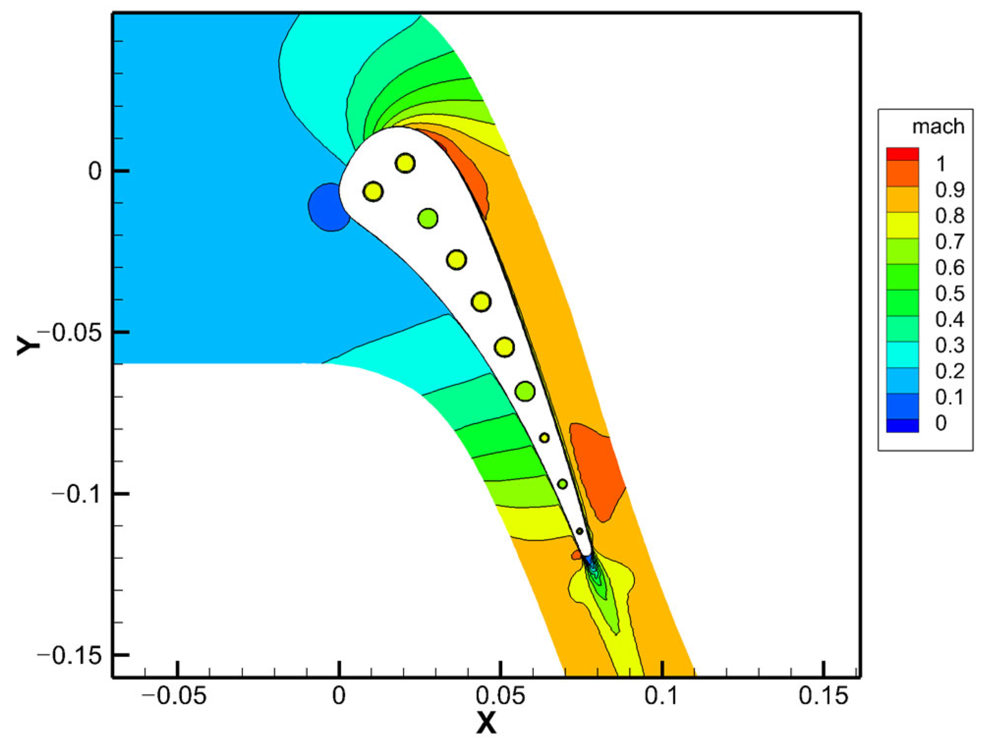
Figure 15 illustrates the isentropic Mach number distribution along the mid-span section of the C3X blade. It is evident that the flow within the blade channel is predominantly subsonic. Notably, a faint shockwave (Mach > 1) is discernible on the suction side at approximately 40% axial chord (Figure 16). Additionally, the leading edge of the blade is characterized by a relatively large arc shape, and the curvature radius exhibits minimal variation. Such a design minimizes energy loss when the incidence angle at the inlet varies significantly. Meanwhile, the influence of these shockwaves on both the pressure and suction sides appears to be minimal. As depicted in Figure 17, the flow state at the trailing edge of the blade is relatively regular, with the vortex growth reaching approximately 1.5 times the diameter of the trailing edge. Simultaneously, there is a small region on the pressure side where the Mach number increases to around 0.93; however, no shockwave or boundary layer separation is formed.
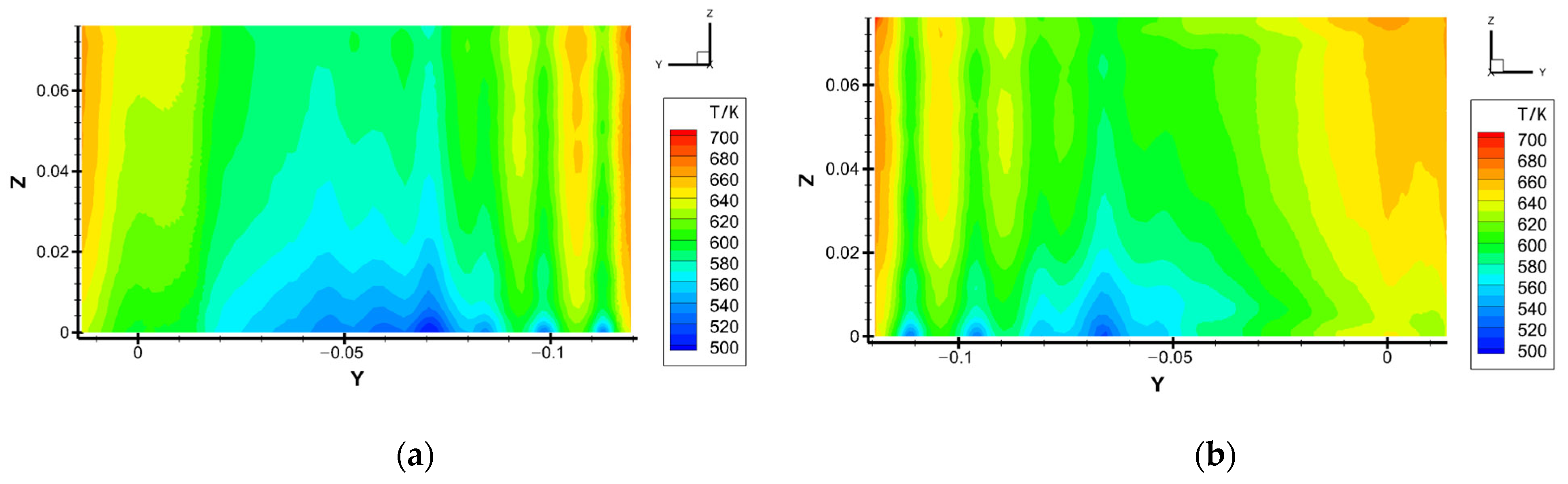
The fluid domain’s coupled temperature contours, as depicted in Figure 18, reveal a uniform variation in the mainstream field, with temperatures consistently surpassing 730 K, with the exception of the vicinity proximal to the interface. In contrast, the internal cooling channel is significantly influenced by the injected cooling airflow, leading to a temperature distribution that closely mirrors that of the incoming.
Figure 19 elucidates the cooling effect through the contours of the surface temperatures, revealing the high-temperature region concentrated at the leading edge of the pressure side due to the synergistic impact of the coupled thermal and structural analyses. Notably, the integration of an internal cooling passage exerts a pronounced cooling influence on both the pressure and suction sides, particularly on the lower extremities.
A comparative analysis of blade surface temperatures at the mid-span location is presented in Figure 20. This figure illustrates that the computational outcomes derived from the AENS model are congruent with the experimental trends observed on the pressure side. However, discrepancies emerge on the suction side, where the computational predictions fall notably below the empirical data within the axial chord length range of approximately 40% to 70%. This divergence is attributable to the complex interplay between the shockwaves and the boundary layer over the blade surface under actual operating conditions, as delineated within the inset circle of the figure.
Comparative analyses of temperature profiles at the mid-span were conducted for two classical turbulence models: the Spalart–Allmaras one-equation model (SA) and the k–ω SST model, as depicted in Figure 21. Similar to the SST model, the temperature of the SA model predictions maintains good agreement with experimental conditions in the wake region behind the pressure side. However, in the axial chord length from the leading edge to the midsection of the suction side, approximately over 40% of the chord’s length, the SA model exhibits a divergence in trend from the experimental data, which can be attributed to the interaction between shockwaves and the boundary layer present in real operating conditions—a phenomenon not well captured by either the SST k–ω or SA models in simulating transitional flows. When comparing conjugate heat transfer calculations from both models, it is evident that the SA method presents notable errors in the vicinity of the leading edge. This discrepancy arises because the precision of the SA turbulence model is significantly affected at regions of high curvature, such as those found at the leading edge, leading to a less satisfactory overall simulation performance compared to the SST model. Conversely, in the more benign regions of the pressure side and the rear portion of the suction side, where flow conditions are less demanding, the results from both turbulence models show greater consistency.
4. Conclusions
In the realm of aerospace engineering, conjugate heat transfer (CHT) analysis stands out as a preeminent technique and has a wide range of engineering application requirements.
In response to these imperatives, the current study harnesses the extensive survey of conjugate heat transfer methodologies and coupling techniques to construct an advanced computational framework termed su-F-TFTB. Grounded on the AENS software platform, this framework facilitates the execution of conjugate heat transfer simulations. A conservation-based heat flux interpolation technique was integrated into AENS software to enhance its capabilities in engineering applications, particularly with respect to the mesh adaptation strategies. As a case in point, a NASA-C3X turbine vane equipped with ten radial cooling passages was applied to be analyzed using AENS v4.0.1 software. A comparative analysis of the pressure distributions across different density meshes was conducted to verify mesh independence. Additionally, the influence of conjugate heat transfer on the temperature distribution was examined, alongside a comparison of the effects of the SA and SST models on the temperature field. The results of the SST model are significantly better than those of the SA model. Overall, the simulation outcomes exhibit a commendable correlation with the empirical findings, thereby substantiating the predictive capabilities of the developed code for the forthcoming analysis of conjugate heat transfer in turbine rotor blades.
Despite the notable strides made by the AENS framework in terms of computational resilience and precision, certain limitations persist. The predictive accuracy for transition regions remains insufficient, as a transition model has not yet been incorporated. In the meantime, the convergence phase of the calculations necessitates a considerable number of iterative procedures and consumes substantial memory resources. As stated in this text, AENS requires approximately 50 h of computation time for a mesh of 9.3 million cells, which may require around 15–18 k iterations for good convergence. However, the commercial software CFX can achieve similar results in only about 1/30th of this time under identical parallel conditions. Obviously, in comparison with leading international software tools, AENS exhibits deficiencies in its computational velocity and convergence rate, which hinder its readiness for widespread engineering applications.
Moving forward, a concerted effort will be directed towards optimizing this soft-ware tool’s performance, with a specific emphasis placed on enhancing its engineering applicability through targeted improvements. These endeavors are poised to address existing shortcomings and propel the AENS framework towards a new paradigm of computational efficiency and robustness.
Author Contributions
Conceptualization, H.Z. and Y.X.; methodology, H.Z.; software, H.Z. and Y.X.; validation, Y.X.; investigation, H.Z.; data curation, Y.X. and D.W.; writing—original draft preparation, H.Z.; writing—review and editing, H.Z.; visualization, Y.X.; supervision, Z.T. and B.L. All authors have read and agreed to the published version of the manuscript.
Funding
This research received no external funding.
Data Availability Statement
The data presented in this study are available on request from the corresponding author due to privacy.
Conflicts of Interest
The authors declare no conflicts of interest.
References
- Perelman, T.L. On Conjugated Problems of Heat Transfer. Int. J. Heat Mass Transfer 1961, 3, 293–303. [Google Scholar] [CrossRef]
- Bohn, D.; Bonhoff, B.; Schonenborn, H. IGTC-108 Combined Aerodynamic and Thermal Analysis of a High-Pressure Turbine Nozzle Guide Vane (Organized Session I Advanced Computational Simulation and Design); Gas Turbine Society of Japan: Yokohama, Japan, 1995. [Google Scholar]
- Bohn, D.E.; Becker, V.J.; Kusterer, K.A. 3-D Conjugate Flow and Heat Transfer Calculations of a Film-Cooled Turbine Guide Vane at Different Operation Conditions. In Proceedings of the ASME 1997 International Gas Turbine and Aeroengine Congress and Exhibition, Orlando, FL, USA, 2–5 June 1997. [Google Scholar] [CrossRef]
- Heidmann, J.D.; Kassab, A.J.; Divo, E.A.; Rodriguez, F.; Steinthorsson, E. Conjugate Heat Transfer Effects on a Realistic Film-Cooled Turbine Vane. In Proceedings of the ASME Turbo Expo Power Land, Sea, Air, Atlanta, GA, USA, 16–19 June 2003. [Google Scholar] [CrossRef]
- Facchini, B.; Magi, A.; Greco, A.S.D. Conjugate Heat Transfer Simulation of a Radially Cooled Gas Turbine Vane. In Proceedings of the ASME Turbo Expo Power Land, Sea, Air, Vienna, Austria, 14–17 June 2004. [Google Scholar] [CrossRef]
- Montomoli, F.; Adami, P.; Martelli, F. A finite-volume method for the conjugate heat transfer in film cooling devices. Proc. Inst. Mech. Eng. Part A 2009, 223, 191–200. [Google Scholar] [CrossRef]
- Montomoli, F.; Adami, P.; Gatta, S.D.; Martelli, F. Conjugate Heat Transfer Modelling in Film Cooled Blades. In Proceedings of the ASME Turbo Expo 2004: Power for Land, Sea, and Air, Vienna, Austria, 14–17 June 2004. [Google Scholar] [CrossRef]
- Zheng, S.-F.; Song, Y.; Xie, G.; Sunden, B. An Assessment of Turbulence Models for Prediction of Conjugate Heat Transfer for a Turbine Vane with Internal Cooling Channels. Heat Transf. Res. 2015, 46, 1039–1064. [Google Scholar] [CrossRef]
- Scholl, S.; Verstraete, T.; Duchaine, F.; Gicquel, L. Conjugate heat transfer of a rib-roughened internal turbine blade cooling channel using large eddy simulation. Int. J. Heat Fluid Flow 2016, 61, 650–664. [Google Scholar] [CrossRef]
- Giles, M.B. Stability analysis of numerical interface conditions in fluid–structure thermal analysis. Int. J. Numer. Methods Fluids 1997, 25, 421–436. [Google Scholar] [CrossRef]
- Desrayaud, G.; Fichera, A.; Lauriat, G. Natural convection air-cooling of a substrate-mounted protruding heat source in a stack of parallel boards. Int. J. Heat Fluid Flow 2007, 28, 469–482. [Google Scholar] [CrossRef]
- Ganesan, V. Non-Reacting and Reacting Flow Analysis in an Aero-Engine Gas Turbine Combustor Using CFD. In Proceedings of the SAE World Congress & Exhibition, Detroit, MI, USA, 16–19 April 2007; Volume 1. [Google Scholar] [CrossRef]
- Rahman, F.; Visser, J.A.; Morris, R.M. Capturing Sudden Increase in Heat Transfer on the Suction Side of a Turbine Blade Using a Navier–Stokes Solver. J. Turbomach. 2005, 127, 552–556. [Google Scholar] [CrossRef]
- Henshaw, W.D.; Chand, K.K. A composite grid solver for conjugate heat transfer in fluid–structure systems. J. Comput. Phys. 2009, 228, 3708–3741. [Google Scholar] [CrossRef]
- Scholl; Sebastian; Verstraete; Tom Stability analysis of partitioned methods for predicting conjugate heat transfer. Int. J. Heat Mass Transfer 2016, 101, 852–869. [CrossRef]
- Roe, B.; Jaiman, R.; Haselbacher, A.; Geubelle, P.H. Combined interface boundary condition method for coupled thermal simulations. Int. J. Numer. Methods Fluids 2010, 57, 329–354. [Google Scholar] [CrossRef]
- Dieter, B.; Jing, R.; Karsten, K. Systematic Investigation on Conjugate Heat Transfer Rates of Film Cooling Configurations. Int. J. Rotating Mach. 2007, 2005, 211–220. [Google Scholar] [CrossRef]
- Papanicolaou, E.; Giebert, D.; Koch, R.; Schulz, A. A conservation-based discretization approach for conjugate heat transfer calculations in hot-gas ducting turbomachinery components. Int. J. Heat Mass Transfer 2001, 44, 3413–3429. [Google Scholar] [CrossRef]
- Crowell, A.R.; Miller, B.A.; Mcnamara, J.J.; Crowell, R.; Mcnamara, J.J. Computational Modeling for Conjugate Heat Transfer of Shock-Surface Interactions on Compliant Skin Panels. In Proceedings of the 13th AIAA Dynamics Specialists Conference, Denver, CO, USA, 5 April 2011; pp. 1–18. [Google Scholar] [CrossRef]
- He, L. Unsteady Conjugate Heat Transfer Modeling. In Proceedings of the ASME Turbo Expo Power Land, Sea, Air, Vancouver, BC, Canada, 6–10 June 2011. [Google Scholar] [CrossRef]
- Keyes, D.E.; Mcinnes, L.C.; Woodward, C.; Gropp, W.; Myra, E.; Pernice, M.; Bell, J.; Brown, J.; Clo, A.; Connors, J. Multiphysics simulations Challenges and opportunities. Int. J. High Perform. C 2014, 27, 4–83. [Google Scholar] [CrossRef]
- Matthies, H.G.; Steindorf, J. Partitioned but strongly coupled iteration schemes for nonlinear fluid-structure interaction. Comput. Struct. 2002, 80, 1991–1999. [Google Scholar] [CrossRef]
- Alonso, J.J.; Hahn, S.; Ham, F.; Herrmann, M.; Wu, X. CHIMPS: A High-Performance Scalable Module for Multi-Physics Simulation. In Proceedings of the 42nd AIAA/ASME/SAE/ASEE Joint Propulsion Conference & Exhibit, Sacramento, CA, USA, 9–12 July 2006. [Google Scholar] [CrossRef]
- Crowell, A.R.; Miller, B.A.; Mcnamara, J.J. Robust and Efficient Treatment of Temperature Feedback in Fluid–Thermal–Structural Analysis. AIAA J. 2014, 52, 2395–2413. [Google Scholar] [CrossRef]
- Sun, Z.; Chew, J.W.; Hills, N.J.; Volkov, K.N.; Barnes, C.J. Efficient Finite Element Analysis/Computational Fluid Dynamics Thermal Coupling for Engineering Applications. J. Turbomach. 2010, 132, 031016. [Google Scholar] [CrossRef]
- Turpin, G. Temporal multiscale strategies for conjugate heat transfer problems. J. Coupled Syst. Multiscale Dyn. 2013, 1, 89–98. [Google Scholar] [CrossRef]
- Baqué, B. A quasi-dynamic procedure for coupled thermal simulations. Int. J. Numer. Methods Fluids 2013, 72, 1183–1206. [Google Scholar] [CrossRef]
- Ganine, V.; Amirante, D.; Hills, N.J. Aero-Thermo-Mechanical Modelling and Validation of Transient Effects in a High Pressure Turbine Internal Air System. In Proceedings of the ASME Turbo Expo: Turbomachinery Technical Conference and Exposition, Seoul, Republic of Korea, 13–17 June 2016. GT2016-57739. [Google Scholar] [CrossRef]
- Voigt, B.A. Manfred Development of a model for unsteady conjugate heat transfer simulations. Prog. Comput. Fluid Dyn. 2019, 19, 69–79. [Google Scholar] [CrossRef]
- Oh, T.K.; Tafti, D.; Nagendra, K. LES-Conjugate Heat Transfer Analysis of a Ribbed Cooling Passage Using the Immersed Boundary Method. In Proceedings of the ASME Turbo Expo: Turbomachinery Technical Conference and Exposition, Phoenix, AZ, USA, 17–21 June 2019. [Google Scholar] [CrossRef]
- Shi, Y.; Ding, S.; Qiu, T.; Liu, C.; Zhang, S. Bi-Fo time scaling method in the numerical simulation of transient conjugate heat transfer. Propuls. Power Res. 2021, 10, 15. [Google Scholar] [CrossRef]
- Wang, P.; Li, Y.; Zou, Z.; Zhang, W. Conjugate heat transfer investigation of cooled turbine using the preconditioned density-based algorithm. Propuls. Power Res 2013, 2, 56–69. [Google Scholar] [CrossRef]
- Zhang, S.; Chen, F.; Liu, H. Time-Adaptive, Loosely Coupled Strategy for Conjugate Heat Transfer Problems in Hypersonic Flows. J. Thermophys. Heat Transfer 2014, 28, 635–646. [Google Scholar] [CrossRef]
- Zhao, X.; Sun, Z.; Tang, L.; Zheng, G. Coupled Flow-Thermal-Structural Analysis of Hypersonic Aerodynamically Heated Cylindrical Leading Edge. Eng. Appl. Comput. Fluid Mech. 2014, 5, 170–179. [Google Scholar] [CrossRef]
- Murty, M.C.; Manna, P.; Chakraborty, D. Conjugate heat transfer analysis in high speed flows. Proc. Inst. Mech. Eng. Part G 2013, 227, 1672–1681. [Google Scholar] [CrossRef]
- John, B.; Senthilkumar, P.; Sadasivan, S. Applied and Theoretical Aspects of Conjugate Heat Transfer Analysis: A Review. Arch. Comput. Methods Eng. 2019, 26, 475–489. [Google Scholar] [CrossRef]
- Boer, A.D.; Zuijlen, A.H.V.; Bijl, H. Review of coupling methods for non-matching meshes. Comput. Methods Appl. Mech. Eng. 2007, 196, 1515–1525. [Google Scholar] [CrossRef]
- Liu, X.; Lu, L. Research on flux conservation interpolation algorithm of patched grid. Comput. Appl. Soft 2012, 29, 275–278. [Google Scholar]
- Farrell, P.E.; Piggott, M.D.; Pain, C.C.; Gorman, G.J.; Wilson, C.R. Conservative interpolation between unstructured meshes via supermesh construction. Comput. Methods Appl. Mech. Eng. 2009, 198, 2632–2642. [Google Scholar] [CrossRef]
- Farrell, P.E.; Maddison, J.R. Conservative interpolation between volume meshes by local Galerkin projection. Comput. Methods Appl. Mech. Eng. 2011, 200, 89–100. [Google Scholar] [CrossRef]
- Xu, C.; Dong, H.; Liu, J. An accurate conservative interpolation method for the mixed grid based on the intersection of grid cells. Combust Explo. Shock+ 2016, 36, 8. [Google Scholar] [CrossRef]
- Cui, P.C.; Tang, J.; Li, B. A Conservative Interpolation method for overset mesh via super mesh. Acta Aeronaut. Astronaut. Sin. 2018, 39, 121569. [Google Scholar] [CrossRef]
- Li, T. Thermal-Flow-Elastic Coupling Numerical Simulation Based on Unstructured Mesh in Air-Cooled Turbine; Harbin Institute of Technology: Harbin, China, 2014. [Google Scholar]
- Hylton, L.D.; Mihelc, M.S.; Turner, E.R.; Nealy, D.A.; York, R.E. Analytical and Experimental Evaluation of the Heat Transfer Distribution over the Surfaces of Turbine Vanes. In Proceedings of the AAS/Division of Dynamical Astronomy Meeting, Chicago, IL, USA, 16–17 June 1983. [Google Scholar]
Figure 1.
Conventional serial staggered (CSS) aerothermal coupling scheme [19].
Figure 1.
Conventional serial staggered (CSS) aerothermal coupling scheme [19].

Figure 2.
Overview of different coupling methods [15].
Figure 2.
Overview of different coupling methods [15].


Figure 4.
Scheme of the iterative unsteady CHT model (uFFTB) [29].
Figure 4.
Scheme of the iterative unsteady CHT model (uFFTB) [29].

Figure 5.
Commonly used fluid–solid grids for conjugate heat transfer [32].
Figure 5.
Commonly used fluid–solid grids for conjugate heat transfer [32].

Figure 6.
Non-matching meshes in 2D [37].
Figure 6.
Non-matching meshes in 2D [37].

Figure 7.
A schematic of the interface grid [43].
Figure 7.
A schematic of the interface grid [43].

Figure 8.
Procedure scheme.

Figure 9.
C3X vane sketch [44].
Figure 9.
C3X vane sketch [44].

Figure 10.
Computational model: (a) C3X blade model and (b) flow field model.

Figure 11.
Solid domain mesh distribution.

Figure 12.
Fluid domain mesh distribution: (a) about 1,500,000 elements; (b) about 2,200,000 elements; (c) about 4,800,000 elements; and (d) about 9,300,000 elements.
Figure 12.
Fluid domain mesh distribution: (a) about 1,500,000 elements; (b) about 2,200,000 elements; (c) about 4,800,000 elements; and (d) about 9,300,000 elements.

Figure 13.
Comparison of pressure at the mid-span of grids with different densities.

Figure 14.
Comparison of average pressure at the mid-span of grids with different densities.

Figure 15.
Mach number field (mid-span).

Figure 16.
Mach number field (local magnification of the leading edge).

Figure 17.
Mach number field (local magnification of the trailing edge).

Figure 18.
Temperature field in the fluid domain.

Figure 19.
Blade surface temperature distribution: (a) pressure side and (b) suction side.

Figure 20.
Temperature at the mid-span.

Figure 21.
Comparison of temperature at the mid-span between the SA and SST turbulence models.


Table 1.
Working condition.
| Boundary Conditions | Parameter/Unit | Value |
|---|---|---|
| Inlet boundary conditions | Working medium | Ideal gas |
| Total pressure/Pa | 413,286 | |
| Total temperature/K | 818 | |
| Mach/Ma | 0.17 | |
| Turbulence intensity/% | 8.3 | |
| Viscosity ratio | 30 | |
| Outlet boundary conditions | Average static pressure/Pa | 254,172 |
| Temperature/K | 800 |
Table 2.
Blade material properties and initial conditions.
| Name/Unit | Value |
|---|---|
| Blade material | 310SS |
| Thermal conductivity coefficient/W/(m·K) | 19.1 |
| Heat capacity/J/(kg·K) | 502 |
| External wall temperature/K | 400 |
| Coolant initial temperature/K | 300 |
Table 3.
Radial coolant flow conditions for the C3X vane.
| # | Diameter/mm | Flow Mass/kg/s | Inlet Temperature/K |
|---|---|---|---|
| 1 | 6.3 | 0.0222 | 342 |
| 2 | 6.3 | 0.0221 | 344 |
| 3 | 6.3 | 0.0218 | 335 |
| 4 | 6.3 | 0.0228 | 336 |
| 5 | 6.3 | 0.0225 | 330 |
| 6 | 6.3 | 0.0225 | 355 |
| 7 | 6.3 | 0.0216 | 336 |
| 8 | 3.1 | 0.00744 | 350 |
| 9 | 3.1 | 0.00477 | 377 |
| 10 | 1.98 | 0.00256 | 387 |
Disclaimer/Publisher’s Note: The statements, opinions and data contained in all publications are solely those of the individual author(s) and contributor(s) and not of MDPI and/or the editor(s). MDPI and/or the editor(s) disclaim responsibility for any injury to people or property resulting from any ideas, methods, instructions or products referred to in the content. |
© 2024 by the authors. Licensee MDPI, Basel, Switzerland. This article is an open access article distributed under the terms and conditions of the Creative Commons Attribution (CC BY) license (https://creativecommons.org/licenses/by/4.0/).
Share and Cite
MDPI and ACS Style
Zha, H.; Xu, Y.; Tang, Z.; Li, B.; Wang, D. Conjugate Heat Transfer Advancements and Applications in Aerospace Engine Technology. Appl. Sci. 2024, 14, 3556. https://0-doi-org.brum.beds.ac.uk/10.3390/app14093556
AMA Style
Zha H, Xu Y, Tang Z, Li B, Wang D. Conjugate Heat Transfer Advancements and Applications in Aerospace Engine Technology. Applied Sciences. 2024; 14(9):3556. https://0-doi-org.brum.beds.ac.uk/10.3390/app14093556
Chicago/Turabian StyleZha, Hao, Yaqian Xu, Zhigong Tang, Bin Li, and Dongzhi Wang. 2024. "Conjugate Heat Transfer Advancements and Applications in Aerospace Engine Technology" Applied Sciences 14, no. 9: 3556. https://0-doi-org.brum.beds.ac.uk/10.3390/app14093556
Note that from the first issue of 2016, this journal uses article numbers instead of page numbers. See further details here.