Article

Soft Robotic Bilateral Rehabilitation System for Hand and Wrist Joints

1
Polytech Lille, University of Lille, Av. Paul Langevin, 59655 Villeneuve d’Ascq, France
2
Biomedical Technologies Division, The University of Texas at Arlington Research Institute, 7300 Jack Newell Blvd S, Fort Worth, TX 76118, USA
3
IMT Mines Alès, 6 Av. de Clavières, 30100 Alès, France
*
Author to whom correspondence should be addressed.
Submission received: 30 March 2024 / Revised: 22 April 2024 / Accepted: 22 April 2024 / Published: 25 April 2024
(This article belongs to the Special Issue Design Methodology for Soft Mechanisms, Machines, and Robots)

Abstract

:
Upper limb functionality is essential to perform activities of daily living. It is critical to investigate neurorehabilitation therapies in order to improve upper limb functionality in post-stroke patients. This paper presents a soft-robotic bilateral system to provide rehabilitation therapy for hand and wrist joints. A sensorized glove that tracks finger and wrist joint movements is worn on the healthy limb, which guides the movement of the paretic limb. The input of sensors from the healthy limb is provided to the soft robotic exoskeleton attached to the paretic limb to mimic the motion. A proportional derivative flow-based control algorithm is used to perform bilateral therapy. To test the feasibility of the developed system, two different applications are performed experimentally: (1) Wrist exercise with a dumbbell, and (2) Object pick-and-place task. The initial tests of the developed system verified its capability to perform bilateral therapy.

1. Introduction

Most (up to 66%) stroke survivors have upper extremity impairments, including the hand and wrist [1]. Therapeutic interventions apply sensory and motor stimulation to induce neuroplastic changes to improve the functional abilities of impaired limbs. Motion (passive motion, task-specific movements, constraint-induced movement, etc.) and/or mirror therapy are applied in stroke rehabilitation settings [2,3]. Motion therapy is typically performed by affected individuals themselves and with assistance from a therapist or robotic device (exoskeleton or end effector). This form of therapy aims to stimulate both sensory and motor pathways. In mirror therapy, a mirror is placed in the patient’s sagittal plane between the arms, which reflects the movements of the non-paretic limb, giving the illusion of movements in the paretic limb. The visual feedback is assumed to stimulate the sensorimotor cortex as well as facilitate neuroplasticity [4]. Although both therapeutic modalities have advantages and disadvantages, they both are proven effective for stroke patients [4,5]. By combining the aspects of motion therapy and mirror therapy, bilateral robot-assisted arm training systems have been investigated that use the motion of the non-paretic side of the upper limb to apply mirrored motion to the paretic side with the assistance of the robotic device. Since many stroke survivors are hemiparetic, this form of therapy has many advantages, as patients can apply therapy by themselves, improving their access to therapy. Because patients are actively engaging in activities that enhance sensory and motor stimulation, bilateral therapy can facilitate neuroplastic changes.
Robotic bilateral therapy uses a leader–follower configuration where the non-paretic limb acts as a leader, providing motor information input to the robotic system, whereas the follower is attached to the paretic limb. Several studies on the development and early-stage trials of robotic bilateral therapy systems are reported in literature [6,7,8,9,10,11,12,13]. An end-effector-based 2-axis wrist and elbow joint motion system has shown its feasibility with healthy subjects and people with post-stroke upper-limb hemiplegia [6,7]. Another end-effector-based assistive system for the upper extremity is used on post-stroke patients in unilateral as well as bilateral settings, which highlighted the benefits of bilateral therapy [8]. Although end-effector-based systems are effective and have been shown as feasible for bilateral therapy interventions, they are only suited for gross motor skill training as the kinematic chain of the arm and hand dictates the movements. For the hand in particular, end-effectors cannot assist in individual joint control, and they can hinder task-specific training because the end-effectors are attached to the fingertips. Recent reports put emphasis on using exoskeletons over end-effectors due to their potential to achieve fine motor training of the upper extremity [9,10]. Developments in upper extremity exoskeletons have shown two main mechanical approaches: rigid and soft robotics. In the rigid robotics approach, some exoskeletons have been developed that combine both the hand and wrist, but are yet to be implemented with bilateral therapy. Regardless, recent reports have described rigid exoskeletons as a less favorable approach compared to soft robotics due to their complex mechanisms and linkages that pose difficulties in fitting to the joints in the fingers and wrist [14,15]. In the soft robotic approach, efforts in bilateral therapy systems have been reported for hand exoskeletons [16,17]. However, we are not aware of any existing soft robotic systems that perform bilateral therapy for both hand and wrist joints. In post-stroke rehabilitation, both fingers (hand) and wrist joint motions are very important, and they are needed together to perform most daily living tasks. Additionally, if there is wrist contracture, it is nearly impossible to do hand training without wrist extension. The two main contributions of this work are:
  • Combination of soft hand-and-wrist exoskeletons for achieving necessary coordinated motion.
  • Bilateral therapy of combined hand and wrist joints.
In this work, we present a soft robotic exoskeleton capable of coordinated assisted movement of the hand and wrist joints as well as bilateral therapy when used with a motion sensor glove that captures non-paretic hand and wrist movement. This paper shows the development and preliminary testing of the hand and wrist soft-robotic bilateral therapy system and associated control algorithm, which has the potential to be used with post-stroke patients to help them regain their hand and wrist functions. The system consists of a hand-and-wrist sensor glove (HWSG), a hand-and-wrist exoskeleton (HWE), and a pneumatic control unit. The HWE combines soft robotic exoskeletons for the hand [18] and wrist [19], which were developed separately in our previous works. Here, we will discuss the detailed system description, operation with the proportional derivative (PD) flow-based control algorithm, and preliminary test results.
This paper is organized as follows: Section 2 describes the components of the bilateral therapy system, while the bilateral therapy control algorithm is described in Section 3. Section 4 describes the experimental setup to perform two applications using the proposed bilateral therapy system. In Section 5, the results and discussion are presented. Section 6 consists of the conclusions and future work.

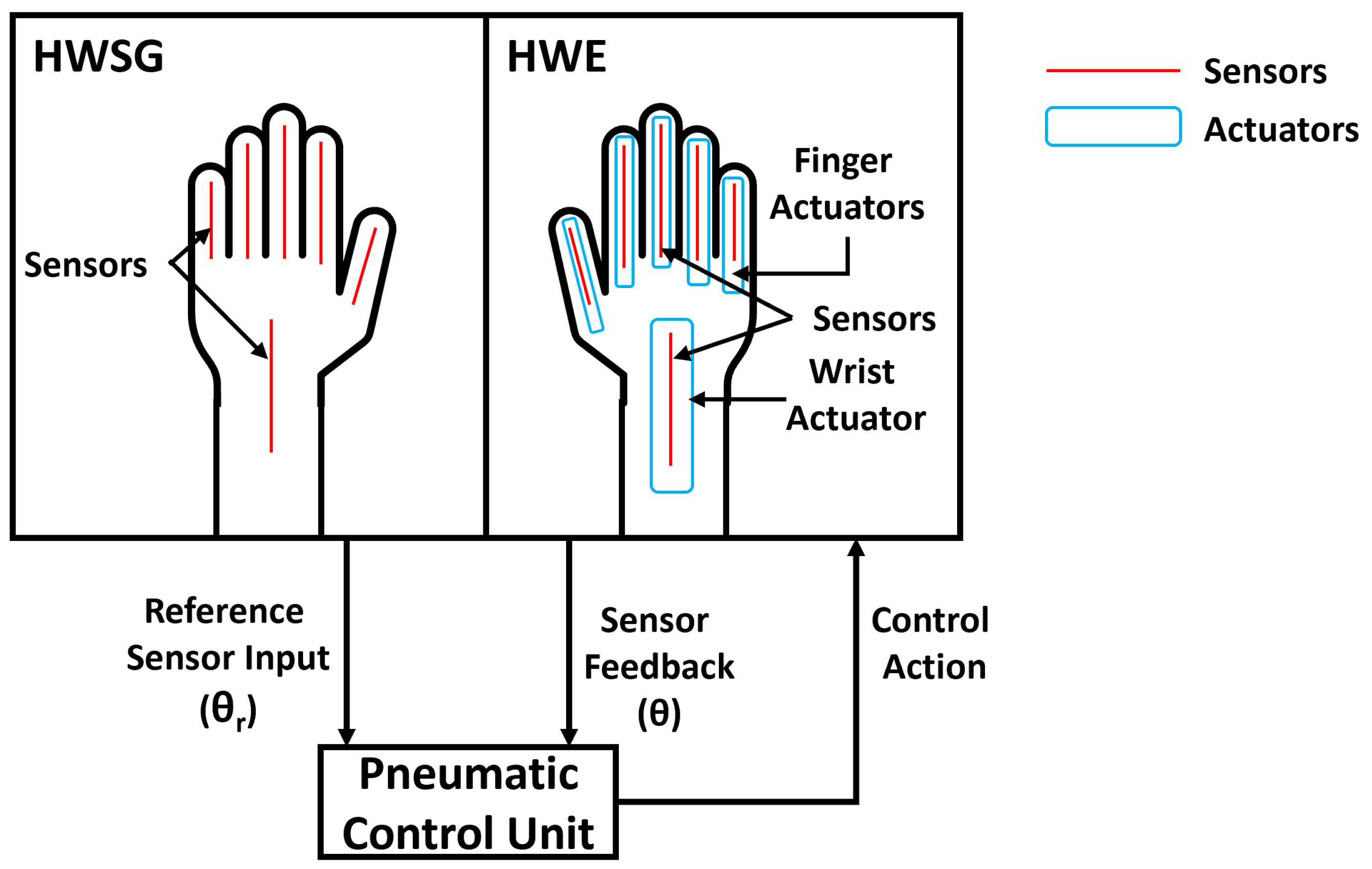
2. Bilateral Therapy System

A schematic of the soft-robotic bilateral rehabilitation therapy system is shown in Figure 1. It consists of an HWSG, an HWE, and a pneumatic control unit.

2.1. Hand-and-Wrist Sensor Glove

The HWSG is to be worn on the healthy limb of the user. The HWSG is equipped with resistance-based flex sensors (from Spectra Symbol) on the fingers and a capacitance-based flex sensor (from Nitto Bend Technologies) on the wrist joint. The capacitance-based sensor for the wrist was chosen due to its capability to read the bidirectional angular motion, while the resistance-based sensors are sufficient for reading the range of motion (ROM) of the fingers. All these sensors are attached to the dorsal side of the glove. These sensors measure the flexion/extension angular motion of the fingers and the wrist joint. The data from these sensors act as reference input data ( θ r ) to the pneumatic control unit.

2.2. Hand-and-Wrist Exoskeleton

The HWE is to be worn on the paretic limb. The soft robotic exoskeleton consists of five finger actuators and a wrist actuator, where flex sensors are attached on the dorsal side of the glove underneath the actuators. The pneumatic control unit takes the angular data from the HWSG flex sensors as input and sends control action in terms of the rate of airflow to the actuators attached to the HWE. This control action mirrors motion from the healthy limb to the paretic limb. The data from sensors ( θ ) attached under each actuator on the HWE act as feedback for the pneumatic control unit.

2.3. Pneumatic Control Unit

The angular motion of actuators attached to the HWE (paretic limb) is controlled by the movement of the healthy limb. The pneumatic control unit schematic for the HWE is presented in Figure 2. The system has both pneumatic and electronic components, and they are controlled by a microcontroller (ESP 32). Pneumatic components used in this control architecture are six proportional valves, six pressure solenoid valves, six vacuum solenoid valves, one pressure pump, and one vacuum pump, whereas electronic components include six pressure sensors, six vacuum sensors, and a microcontroller. As the volume of the wrist actuator is larger than any of the finger actuators, both the solenoid and the proportional valves used for the wrist actuator have bigger orifices. The flex sensors placed in the HWSG and HWE are interfaced with the microcontroller. Resistance-based flex sensors (used for finger joints) communicate with the microcontroller through ADC pins, while capacitance-based flex sensors (placed at the wrist joint) communicate with the microcontroller using the I2C bus. The pneumatic components are used to provide pressure/vacuum to the HWE actuators to create the required angular movement of fingers and wrist joints. Proportional valves use pulse width modulation (PWM) signals to vary their orifice size, which controls the airflow in/out of actuators. The pressure/vacuum provided to each individual finger actuator and wrist actuator is measured through pressure/vacuum sensors, and these sensors provide feedback to the microcontroller to ensure actuators do not exceed pressure limits. The model, dimensions, and weight of each component of the pneumatic control unit are listed in Table 1. The total weight of the pneumatic control unit, including all of the components, is 1.6 kg. The weight of the HWSG and HWE gloves are 74 g and 398 g, respectively.

3. Control Algorithm

A proportional-derivative (PD) flow-based control algorithm was developed and implemented on the hand-and-wrist soft-robotic bilateral system. The HWSG was worn on the healthy hand. While the healthy hand moved, angle and velocity data from the flex sensors were recorded. The raw angle data from flex sensors, especially from resistance-based sensors, were generally noisy. In order to address this, the spectral analysis of sensor signals was performed, and a first-order low-pass filter with a cut-off frequency of 1 Hz was chosen. The filtered data acted as reference data ( θ r , ω r ) for the closed-loop PD control algorithm. The control algorithm ensured that the paretic limb followed the reference trajectories from the HWSG by receiving feedback from the HWE sensor data.
The PD control algorithm controls the angular position and speed of the joints by changing the airflow, as shown in Figure 3. This control allows the soft robotic actuators to mimic the reference hand-and-wrist joint trajectories (angular position ( θ r ) and angular velocity ( ω r )). The reference trajectories generated by HWSG are compared with the sensor feedback from the HWE, and the control algorithm uses the error (Equation (1)) to decide on a control action which is shown in Equation (2). The control action ( a f l o w ) changes the orifice size of the proportional valve to adjust the rate of airflow to the soft actuators (fingers and wrist) as per the reference trajectories from the HWSG on the healthy limb. The orifice size is adjusted based on the PWM signal, which is between 0 ( a m i n ) to 4096 ( a m a x ), where 0 indicates a fully closed valve and 4096 is fully open. Therefore, the output of the controller is the PWM signal to be provided to the proportional valve. If the control action value ( a f l o w ) is less than a m i n or higher than a m a x , it will be considered to be a m i n or a m a x , respectively.
e = θ r θ , e ˙ = ω r ω
a f l o w = a m i n : a f l o w < a m i n k p e + k d e ˙ : a m i n < a f l o w < a m a x a m a x : a m a x < a f l o w
Here, k p and k d are the parameters of the PD control algorithm. The k p and k d control parameters are determined for each actuator by their model estimation. For example, the estimation process for the wrist actuator includes recording the experimental data of the bending angle of the wrist actuator, as shown in Figure 4a. These data are collected while PWM is 2500, which means the proportional valve is approximately 60% open. This PWM is chosen, as the operation of the system is smooth, without any jerk, at this value. Despite the soft actuator’s bending behavior being nonlinear, experimental findings indicate that a linear approximation is acceptable when the system functions within an angular motion range of 0–50 degrees. Therefore, the input PWM to the proportional valve and the output bending angle θ of the soft robotic actuator can be approximated as a linear system.
The state–space formulation [20] for a linear time-invariant dynamic system can be stated as:
x ˙ ( t ) = A x ( t ) + B u ( t τ ) , y ( t ) = C x ( t )
Here, x is the state vector, y is the system output, u is the system input, A is the state matrix, B is the input matrix, C is the output matrix, and τ is the input time delay. In our case, the system output y is angle θ and the system input u is the PWM signal to the proportional valve. To determine the model parameters of a soft pneumatic actuator, the system input PWM is maintained as a constant, while the system output angle θ is obtained through experimentation (Figure 4a). By utilizing experimental data comprising PWM and θ , the system can be estimated by employing an iterative estimation technique aimed at minimizing prediction errors between the experimental data θ and the estimated system output [21]. Therefore, using the input data (PWM = 2500) to the proportional valve and the acquired output data θ , the state–space model is identified. The state matrix A, input matrix B, and output matrix C are estimated. The output of the estimated state–space model is compared with the experimental recording shown in Figure 4b.
Using the estimated state–space model, a simulation model of the control algorithm was constructed in Matlab/Simulink as shown in Figure 4c. The simulation model had a state–space model block, a reference command block, and a PD control block. Using the simulation method, the PD parameters of the wrist actuator were estimated. The estimated parameters k p and k d were 8 and 6.5, respectively. These values were further tuned using the experimental data, which resulted in k p = 8.1 and k d = 6.7. Although the finger actuators vary in length to match each finger size, the same linear trend of experimental data was found for all finger actuators in the linear range of 0–180 degrees. Therefore, the same procedure (as discussed above for the wrist actuator) was followed to estimate k p and k d parameters for finger actuators. Table 2 shows the tuned values of k p and k d parameters.
The soft-robotic hand-and-wrist exoskeleton (HWE) interacts with the paretic human limb. Therefore, a safety limit of actuation pressure/vacuum is provided to the control algorithm to avoid any harm to the system or the human. Pressure and vacuum sensors continuously monitor the safety limits, and the system will shut off if the sensors detect pressure beyond their set limits. This control algorithm is studied with the proposed soft robotic bilateral system experimentally in the next section.

4. Experimental Setup

An experimental setup is prepared to validate the proposed soft-robotic bilateral rehabilitation therapy system for fingers and wrist joints. The aim of these experiments is to show the capability of the HWE to mimic the same joint motion as the HWSG using the developed control algorithm. To demonstrate this, two tasks were selected that are used in activities of daily living and rehabilitation exercises. These tasks also allow observing the feasibility of the system for its intended use.

4.1. Materials

The first step was to manufacture soft actuators. RTV silicone rubber (XIAMETER® RTV-4234-T4, Xiameter®, Dow Corning) material was used to manufacture both finger and wrist actuators. The liquid polymer was compression molded, followed by an over-molding step. SOLIDWORKS® software was used to design all the mold parts, and these parts were 3D printed using a high-resolution printer (ProJet 6000 HD SLA). The detailed process was reported in previous works [18,19]. Figure 5a shows the fabricated actuators for fingers and wrist. For both the HWSG and HWE, a fabric wearable was manufactured by sewing a glove and wrist sleeve together with pockets to house the sensors. For the HWE only, actuators were attached over the sensors. The HWSG (right hand) and HWE (left hand) are both shown in Figure 5b.

4.2. Methods

To validate the functionality of the bilateral robotic system, a flexion/extension exercise was performed for each joint to measure the accuracy of PD control. Once verified, two different experiments were performed: (1) a wrist exercise using a dumbbell, and (2) a pick-and-place task. During both experiments, a healthy volunteer wore the HWSG on their right hand and the HWE on their left hand (Figure 5b) (No participant was recruited for this study. All the experimental tests were performed on one of our team members. At our institution, we are permitted to perform benchtop tests among research staff during the development phase of research without any IRB and regulatory approval). The user put the left hand in a relaxed position without any voluntary muscle activity to check the assistive performance of the hand-and-wrist bilateral soft robotic system, where the right hand with HWSG could guide the left hand of the user. The experiments involved flexion/extension of both fingers and wrist joints. Change in angle over time was measured by all flex sensors, and the data were plotted to compare the shape of trajectories between the reference data ( θ r ) from the HWSG and measured data ( θ ) from HWE.
It should be noted that a healthy volunteer was used in this study to verify the safety and capability of the robotic bilateral therapy system to achieve the reference angles determined by the dynamic motions of the non-paretic hand. In practical applications, the therapy of a person with hemiparesis or other hand conditions may require a more personalized range of motion limits to ensure the safety and effectiveness of treatment. Considering these factors, the PD controller has been designed so that parameters for the range of motion and speed can be set by a therapist. This will allow the patient to still use their non-paretic hand to control the motions of their paretic hand using the bilateral therapy system while maintaining safety limits regarding the angle, speed, and force applied by the HWE.

4.2.1. Wrist Exercise with Dumbbell

This experiment involved performing hand and wrist flexion/extension exercises using input from the HWSG to send control action to the HWE for assisting in grasping and lifting a dumbbell. As shown in Figure 6a–e, this exercise was performed in five steps: (a) Put the dumbbell in the hand with HWE; (b) Flex the fingers of HWSG hand to make HWE hand hold the dumbbell; (c) Flex the wrist joint to perform the exercise; (d) Extend the wrist joint; (e) Extend the fingers to release dumbbell. Two reps of this exercise were performed during this test.

4.2.2. Object Pick-and-Place Task

This test was performed by using input from the HWSG to send control action to the HWE for assisting in an object pick-and-place task. As shown in Figure 7a–e, this test was performed in five steps: (a) Put both hands in an extended position where the hand with HWE is close to an object (an empty plastic bottle in this case); (b) Grab the object with the HWE hand by flexing the fingers of the HWSG hand; (c) Flex the wrist joint to move the object to the target position; (d) Extend fingers to release the object at the target position; (e) Extend the wrist joint to move the hand back to the initial position.

5. Results and Discussion

A verification of the PD controller was performed and experiments were carried out to evaluate the performance of the bilateral soft robotic system in two different applications. A healthy volunteer wore the robotic system for both experiments and the results are as follows:
To check the performance of the PD controller, we performed a test without any object manipulation (only flexion/extension of fingers and wrist joint of the HWE controlling through the HWSG). The flexion/extension reference angles ( θ r ) for fingers and wrist were chosen as 100 / 0 and 60 / 0 , respectively. This test confirmed that the PD controller performed well in achieving the reference angles. During this test, the average errors for little, ring, middle, index, thumb fingers, and wrist were 7.319, 0.954, 3.301, 0.369, 2.077, and 2.296 degrees, respectively. The results for this flexion/extension exercise are shown in Figure 8.

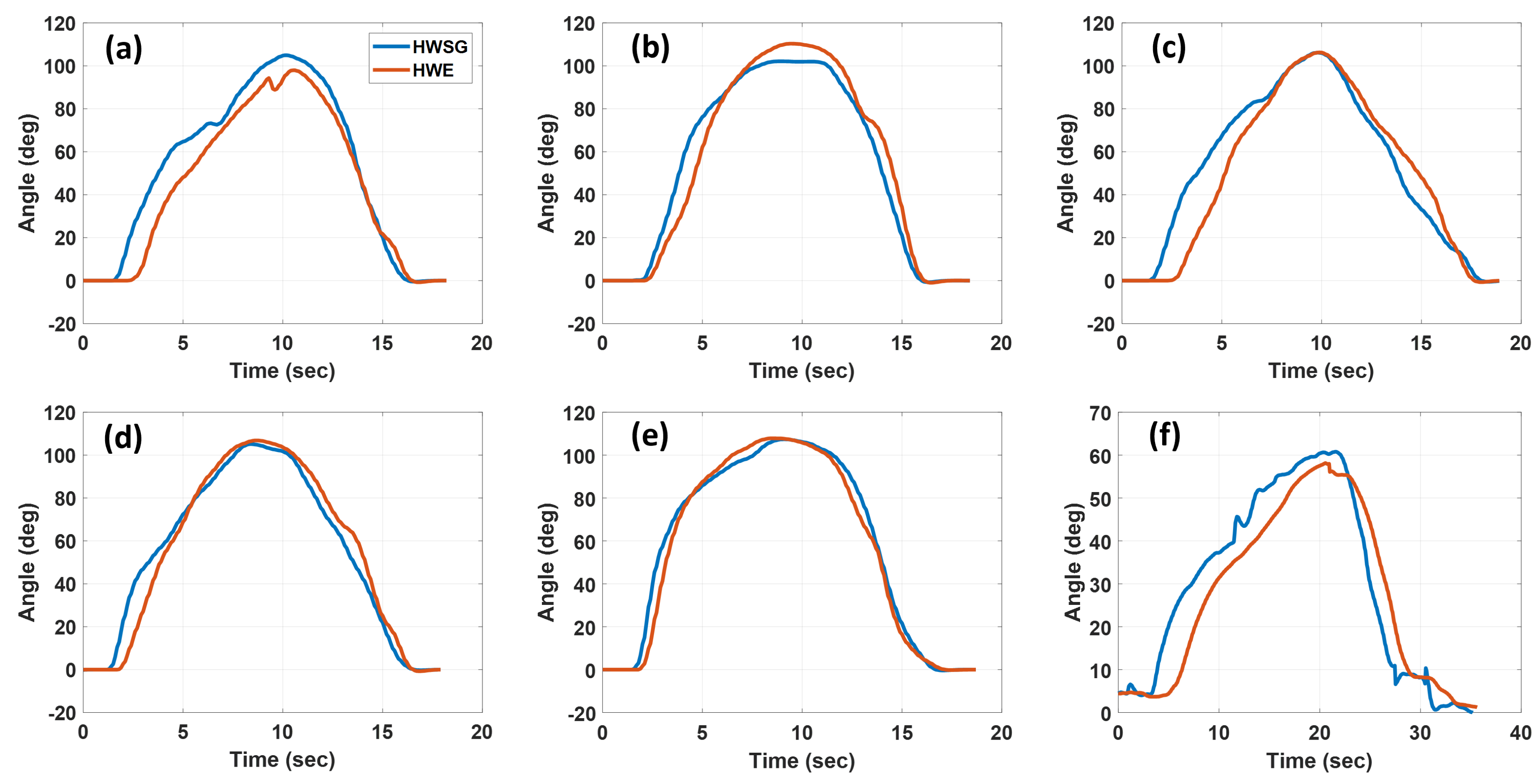
5.1. Wrist Exercise with Dumbbell

Five steps for a wrist exercise with a dumbbell (Figure 6) were performed using the soft robotic bilateral system. Figure 9 shows the sensor data from HWSG while performing the required steps for the exercise. This shows the angular movement of the fingers and wrist during two repetitions of grasping the dumbbell and performing the wrist exercise. Figure 10 compares the finger and wrist joint angles for the HWSG versus the HWE while performing two repetitions of the exercise. For this exercise, the finger joints moved in the range of 100–150 degrees of flexion, and the wrist joint moved to 50 degrees.

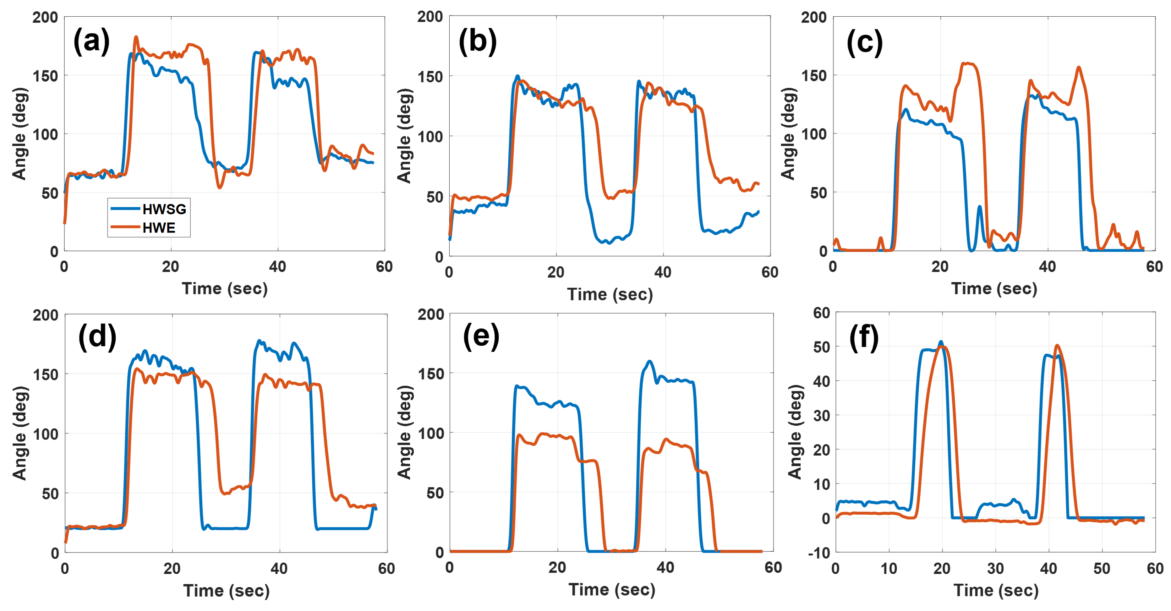
5.2. Object Pick-and-Place Task

Five steps for the object pick-and-place task (Figure 7) were performed using the soft robotic bilateral system. Figure 11 shows the sensor data (fingers and wrist joint angles) from HWSG while picking and placing an object. Figure 12 compares the finger and wrist joint angles for the HWSG and the HWE during the pick-and-place task. For this task, finger joints moved in the range of 90–130 degrees of flexion, and the wrist joint moved to 60 degrees.

5.3. Discussions

The observations from the results of both applications are as follows:
  • Qualitatively, the graphs demonstrate that the fingers and wrist joints assisted by HWE followed the same trajectories as guided by the HWSG, which verifies the functionality of the bilateral therapy algorithm.
  • In this work, the main focus was to show that the motions of both HWSG and HWE followed a similar trajectory during a rehabilitation task rather than error computation. Regardless, discrepancies between the reference ( θ r ) and measured ( θ ) angles were observed in some joints and could be attributed to the nature of the experiment. In this work, a human controlled the sensor glove, and object manipulation was involved in the experiments. Therefore, the user had no sense of how much angle to move their fingers in order for the HWE to grab an object. The joint angles in HWSG could move to higher angles than HWE, as there was no object present in the HWSG hand to interfere with the joint motion. However, a similar bilateral soft robotic system for the hand (wrist excluded) was tested in our previous work [16] and showed minimal error between the angular motion of the sensor glove versus the robotic glove while both gloves were attached to artificial hand models.
  • It was observed that the gaps (angle difference) between the angles recorded by the HWSG and HWE were greater in the thumb actuators than in all other actuators (Figure 10e and Figure 12e). This was because the user was holding either a dumbbell or an object in the HWE hand, which restricted the movement of the thumb once it touched the object, whereas, in the case of the HWSG hand, there was no object to restrict the movement.
  • Results from both applications show that all the finger actuators inflated quicker than the wrist actuator. This was because finger actuators have a very small volume to be filled compared to that of the wrist actuator. This situation can be resolved by using a bigger proportional valve for the wrist actuator.
  • In the case of deflation, finger actuators deflated slower than the wrist actuator. This was because the orifice size of the proportional valves used to deflate the finger actuators was small in comparison to the proportional valve used for the wrist actuator. For the fingers and wrist actuators, the orifice sizes of proportional valves were 0.25 mm (Parker-910-000042-030) and 1.02 mm (Parker-910-000045-030), respectively. Conductivity (C) of a pipe under vacuum flow is given as [22],
    C = 1.35 d 4 l p
    where C, d, l, and p are conductivity, diameter of pipe, length, and air pressure, respectively. From Equation (4) and the diameters of the proportional valves (0.25 mm for fingers and 1.02 mm for wrist actuator), it is clear that flow is approximately 10 3 times higher for the wrist actuator during deflation.

6. Conclusions

This study developed a soft-robotic bilateral therapy system using a soft-robotic hand-and-wrist exoskeleton. As the system provides assistive motion to both the hand and wrist while allowing free movement of the entire upper limb, it has the potential to facilitate the restoration of motor functions in the upper limbs of stroke patients through task-specific rehabilitation. A PD flow-based controller was developed to enable bilateral therapy. The proposed system was tested for two different task-oriented applications: performing wrist exercises with a dumbbell and object pick-and-place tasks. The results from both experiments showed the feasibility of this soft robotic bilateral therapy system. In the future, both the HWSG and HWE will be equipped with force sensors on the palmar side, which will provide the grip force feedback between the fingers and the object during object manipulation tasks. Force control will be added to the algorithm along with angular position control. Additionally, pneumatic control hardware will be updated to obtain the air flow rate needed to address any delays between sensor signal and actuation.

Author Contributions

Conceptualization, I.S., A.J., Y.G. and M.B.J.W.; methodology, I.S., Y.G. and M.B.J.W.; software, T.R., I.S., B.B. and Y.G.; validation, T.R., I.S., V.E., Y.G. and B.B.; formal analysis, T.R., I.S., B.B., V.E., A.J., R.M. and M.B.J.W.; writing—original draft preparation, T.R., I.S., V.E., A.J. and M.B.J.W.; writing—review and editing, I.S., A.J., V.E. and M.B.J.W.; supervision, R.M. and M.B.J.W. All authors have read and agreed to the published version of the manuscript.

Funding

This research received no external funding.

Data Availability Statement

The raw data supporting the conclusions of this article will be made available by the authors on request.

Conflicts of Interest

The authors declare no conflicts of interest.

Abbreviations

The following abbreviations are used in this manuscript:
HWSGHand-and-wrist sensor glove
HWEHand-and-wrist exoskeleton
PDProportional derivative
ADCAnalog-to-digital converter
ROMRange of motion
PWMPulse width modulation

References

  1. Nogueira, N.G.D.H.M.; Parma, J.O.; de Assis Leão, S.E.S.; de Souza Sales, I.; Macedo, L.C.; Galvão, A.C.D.R.; de Oliveira, D.C.; Murça, T.M.; Fernandes, L.A.; Junqueira, C.; et al. Mirror therapy in upper limb motor recovery and activities of daily living, and its neural correlates in stroke individuals: A systematic review and meta-analysis. Brain Res. Bull. 2021, 177, 217–238. [Google Scholar] [CrossRef] [PubMed]
  2. Thieme, H.; Morkisch, N.; Mehrholz, J.; Pohl, M.; Behrens, J.; Borgetto, B.; Dohle, C. Mirror therapy for improving motor function after stroke. Cochrane Database Syst. Rev. 2018, 7, CD008449. [Google Scholar] [CrossRef] [PubMed]
  3. Yuan, R.; Qiao, X.; Tang, C.; Zhou, T.; Chen, W.; Song, R.; Jiang, Y.; Reinhardt, J.D.; Wang, H. Effects of Uni-vs. Bilateral Upper Limb Robot-Assisted Rehabilitation on Motor Function, Activities of Daily Living, and Electromyography in Hemiplegic Stroke: A Single-Blinded Three-Arm Randomized Controlled Trial. J. Clin. Med. 2023, 12, 2950. [Google Scholar] [CrossRef] [PubMed]
  4. Winstein, C.; Varghese, R. Been there, done that, so what’s next for arm and hand rehabilitation in stroke? NeuroRehabilitation 2018, 43, 3–18. [Google Scholar] [CrossRef] [PubMed]
  5. Lo, A.C.; Guarino, P.D.; Richards, L.G.; Haselkorn, J.K.; Wittenberg, G.F.; Federman, D.G.; Ringer, R.J.; Wagner, T.H.; Krebs, H.I.; Volpe, B.T.; et al. Robot-assisted therapy for long-term upper-limb impairment after stroke. N. Engl. J. Med. 2010, 362, 1772–1783. [Google Scholar] [CrossRef] [PubMed]
  6. Beom, J.; Koh, S.; Nam, H.S.; Kim, W.; Kim, Y.; Seo, H.G.; Oh, B.M.; Chung, S.G.; Kim, S. Robotic mirror therapy system for functional recovery of hemiplegic arms. JoVE (J. Vis. Exp.) 2016, 114, e54521. [Google Scholar]
  7. Nam, H.S.; Koh, S.; Beom, J.; Kim, Y.J.; Park, J.W.; Koh, E.S.; Chung, S.G.; Kim, S. Recovery of proprioception in the upper extremity by robotic mirror therapy: A clinical pilot study for proof of concept. J. Korean Med. Sci. 2017, 32, 1568–1575. [Google Scholar] [CrossRef] [PubMed]
  8. Wu, C.Y.; Yang, C.L.; Chen, M.D.; Lin, K.C.; Wu, L.L. Unilateral versus bilateral robot-assisted rehabilitation on arm-trunk control and functions post stroke: A randomized controlled trial. J. Neuroeng. Rehabil. 2013, 10, 35. [Google Scholar] [CrossRef] [PubMed]
  9. Moggio, L.; de Sire, A.; Marotta, N.; Demeco, A.; Ammendolia, A. Exoskeleton versus end-effector robot-assisted therapy for finger-hand motor recovery in stroke survivors: Systematic review and meta-analysis. Top. Stroke Rehabil. 2022, 29, 539–550. [Google Scholar] [CrossRef] [PubMed]
  10. Gassert, R.; Dietz, V. Rehabilitation robots for the treatment of sensorimotor deficits: A neurophysiological perspective. J. Neuroeng. Rehabil. 2018, 15, 46. [Google Scholar] [CrossRef] [PubMed]
  11. Ueki, S.; Kawasaki, H.; Ito, S.; Nishimoto, Y.; Abe, M.; Aoki, T.; Ishigure, Y.; Ojika, T.; Mouri, T. Development of a hand-assist robot with multi-degrees-of-freedom for rehabilitation therapy. IEEE/ASME Trans. Mechatron. 2010, 17, 136–146. [Google Scholar] [CrossRef]
  12. De la Cruz-Sánchez, B.A.; Arias-Montiel, M.; Lugo-González, E. EMG-controlled hand exoskeleton for assisted bilateral rehabilitation. Biocybern. Biomed. Eng. 2022, 42, 596–614. [Google Scholar] [CrossRef]
  13. Maciejasz, P.; Eschweiler, J.; Gerlach-Hahn, K.; Jansen-Troy, A.; Leonhardt, S. A survey on robotic devices for upper limb rehabilitation. J. Neuroeng. Rehabil. 2014, 11, 3. [Google Scholar] [CrossRef] [PubMed]
  14. Polygerinos, P.; Wang, Z.; Galloway, K.C.; Wood, R.J.; Walsh, C.J. Soft robotic glove for combined assistance and at-home rehabilitation. Robot. Auton. Syst. 2015, 73, 135–143. [Google Scholar] [CrossRef]
  15. Haghshenas-Jaryani, M.; Patterson, R.M.; Bugnariu, N.; Wijesundara, M.B. A pilot study on the design and validation of a hybrid exoskeleton robotic device for hand rehabilitation. J. Hand Ther. 2020, 33, 198–208. [Google Scholar] [CrossRef] [PubMed]
  16. Haghshenas-Jaryani, M.; Pande, C.; Wijesundara, B.M. Soft robotic bilateral hand rehabilitation system for fine motor learning. In Proceedings of the 2019 IEEE 16th International Conference on Rehabilitation Robotics (ICORR), Toronto, ON, Canada, 24–28 June 2019; pp. 337–342. [Google Scholar]
  17. Ma, D.; Li, X.; Xu, Q.; Yang, F.; Feng, Y.; Wang, W.; Huang, J.J.; Pei, Y.C.; Pan, Y. Robot-Assisted Bimanual Training Improves Hand Function in Patients with Subacute Stroke: A Randomized Controlled Pilot Study. Front. Neurol. 2022, 13, 884261. [Google Scholar] [CrossRef] [PubMed]
  18. Haghshenas-Jaryani, M.; Nothnagle, C.; Patterson, R.M.; Bugnariu, N.; Wijesundara, M.B. Soft robotic rehabilitation exoskeleton (rehab glove) for hand therapy. In Proceedings of the International Design Engineering Technical Conferences and Computers and Information in Engineering Conference, Cleveland, OH, USA, 6–9 August 2017; Volume 58158, p. V003T13A005. [Google Scholar]
  19. Singh, I.; Erel, V.; Gu, Y.; Lindsay, A.R.; Patterson, R.M.; Swank, C.; Wijesundara, M.B. Development of Soft Pneumatic Actuator Based Wrist Exoskeleton for Assistive Motion. In Proceedings of the 2023 IEEE/ASME International Conference on Advanced Intelligent Mechatronics (AIM), Seattle, WA, USA, 28–30 June 2023; pp. 359–366. [Google Scholar]
  20. Mikova, L.; Gmiterko, A.; Hroncova, D. State space representation of dynamical systems. Am. J. Mech. Eng. 2016, 4, 385–389. [Google Scholar]
  21. Van Overschee, P.; De Moor, B. Subspace Identification for Linear Systems: Theory—Implementation—Applications; Springer Science & Business Media: Berlin/Heidelberg, Germany, 2012. [Google Scholar]
  22. Conductance. Available online: https://www.pfeiffer-vacuum.com/en/know-how/introduction-to-vacuum-technology/fundamentals/conductance/ (accessed on 1 October 2023).
Figure 1. Bilateral therapy system diagram: this system comprises a hand-and-wrist sensor glove (HWSG), a soft robotic exoskeleton called hand-and-wrist exoskeleton (HWE), and a pneumatic control unit.
Machines 12 00288 g001
Figure 2. Schematic diagram of pneumatic control unit for soft robotic bilateral therapy system.
Machines 12 00288 g002
Figure 3. Proportional derivative (PD) flow-based control algorithm diagram for soft robotic bilateral system.
Machines 12 00288 g003
Figure 4. Control parameters estimation (a) experimental recorded wrist angle, (b) output of the state–space model compared with experimental values, (c) simulation model of control with estimated state–space model.
Machines 12 00288 g004
Figure 5. Soft robotic bilateral therapy system: (a) finger and wrist actuators, (b) HWSG and HWE.
Machines 12 00288 g005
Figure 6. Five steps (ae) in series to perform wrist exercise using a dumbbell.
Machines 12 00288 g006
Figure 7. Five steps (ae) in series to perform object pick-and-place task.
Machines 12 00288 g007
Figure 8. Comparison of angular movement of the HWSG with the HWE for (a) little, (b) ring, (c) middle, (d) index, (e) thumb fingers, and (f) wrist, while performing flexion/extension.
Machines 12 00288 g008
Figure 9. Sensor data from the HWSG while performing two reps of wrist exercise with a dumbbell.
Machines 12 00288 g009
Figure 10. Comparison of angular movement of the HWSG with the HWE for (a) little, (b) ring, (c) middle, (d) index, (e) thumb fingers, and (f) wrist, while performing wrist exercise using a dumbbell.
Machines 12 00288 g010
Figure 11. Sensor data from the HWSG while performing the object pick-and-place task.
Machines 12 00288 g011
Figure 12. Comparison of angular movement of the HWSG with the HWE for (a) little, (b) ring, (c) middle, (d) index, (e) thumb fingers, and (f) wrist, while performing the pick-and-place task.
Machines 12 00288 g012
Table 1. Specifications of components used in pneumatic control unit.
Component NameModelDimensions (L × W × H) mmWeight (g)
PumpParker D1020-23-0185 × 30 × 75257.48
Solenoid Valve (Fingers)Clippard E210C45 × 15 × 2010.01
Solenoid Valve (Wrist)Clippard E210H45 × 15 × 209.91
Proportional Valve (Fingers)Parker 910-000042-03030 × 10 × 2047.00
Proportional Valve (Wrist)Parker 910-000045-03030 × 10 × 2047.00
Pressure Sensor (Range: 0 to 206.84 kPa)Honeywell ABPMANN004BGAA57.3 × 6.3 × 18.67.08
Vacuum Sensor (Range: −115 to 0 kPa)NXP MPXV6115V18.01 × 10.54 × 5.381.30
MicrocontrollerESP-3250 × 25 × 1010.46
Table 2. Tuned control parameters k p and k d for finger and wrist actuators.
k p k d
Thumb Actuator5.54
Index Actuator4.53.4
Middle Actuator5.84.6
Ring Actuator4.53.4
Little Actuator5.24.1
Wrist Actuator8.16.7
Disclaimer/Publisher’s Note: The statements, opinions and data contained in all publications are solely those of the individual author(s) and contributor(s) and not of MDPI and/or the editor(s). MDPI and/or the editor(s) disclaim responsibility for any injury to people or property resulting from any ideas, methods, instructions or products referred to in the content.

