Article

Design and Fabrication of 3.5 GHz Band-Pass Film Bulk Acoustic Resonator Filter

1
The Institute of Technological Sciences, Hubei Key Laboratory of Electronic Manufacturing and Packaging Integration, Wuhan University, Wuhan 430072, China
2
School of Physics & Technology, Wuhan University, Wuhan 430072, China
3
Wuhan Institute of Quantum Technology, Wuhan 430072, China
*
Authors to whom correspondence should be addressed.
These authors contributed equally to this work.
Submission received: 26 March 2024 / Revised: 19 April 2024 / Accepted: 19 April 2024 / Published: 25 April 2024

Abstract

:
With the development of wireless communication, increasing signal processing presents higher requirements for radio frequency (RF) systems. Piezoelectric acoustic filters, as important elements of an RF front-end, have been widely used in 5G-generation systems. In this work, we propose a Sc0.2Al0.8N-based film bulk acoustic wave resonator (FBAR) for use in the design of radio frequency filters for the 5G mid-band spectrum with a passband from 3.4 to 3.6 GHz. With the excellent piezoelectric properties of Sc0.2Al0.8N, FBAR shows a large K e f f 2 of 13.1%, which can meet the requirement of passband width. Based on the resonant characteristics of Sc0.2Al0.8N FBAR devices, we demonstrate and fabricate different ladder-type FBAR filters with second, third and fourth orders. The test results show that the out-of-band rejection improves and the insertion loss decreases slightly as the filter order increases, although the frequency of the passband is lower than the predicted ones due to fabrication deviation. The passband from 3.27 to 3.47 GHz is achieved with a 200 MHz bandwidth and insertion loss lower than 2 dB. This work provides a potential approach using ScAlN-based FBAR technology to meet the band-pass filter requirements of 5G mid-band frequencies.

1. Introduction

Wireless communication has overcome the limitations of time and distance on our communication and allows us to transfer information quickly [1,2,3,4]. In particular, fifth-generation (5G) systems have introduced new services to support higher data transmission rates of wireless communication [5,6,7]. The proliferation of 5G communications has led to a gradual increase in data transmission bands, with frequencies covered ranging from 2.4 GHz to 5 GHz [8,9]. Higher frequencies and frequency bands have been pursued to improve radio frequency (RF) systems, especially the filtering action of RF filters. As important elements in 5G data transmission, filters based on surface acoustic wave (SAW) resonators are difficult to use at a frequency higher than 3 GHz because of performance degradation at high frequencies [10,11,12]. The IHP SAW can be used in higher frequency bands, but it requires more complex processing of the multi-layered structure, such as film transfer and bonding process [13,14,15]. On the contrary, a bulk acoustic wave (BAW) filter seems a better choice for 5G communication. Most commercially available BAW filters are constructed with film bulk acoustic resonators (FBARs), in which an air cavity is created between the bottom electrode and the carrier wafer. FBARs can obtain a better effective electromechanical coupling coefficient ( K e f f 2 ) and provide a higher quality factor (Q) [16,17]. FBARs are preferred for higher-frequency applications due to characteristics such as good electivity and high power-handling.
For FBARs and FBAR-based filters, which are capable of processing the high frequencies of the 5G system, higher-frequency operations need a reduction in the piezoelectric layer thickness [18,19,20], while commercially available AlN-based FBARs are capable of providing high longitudinal sound velocity v (11,354 m/s) and low acoustic and dielectric losses. However, studies have attempted to scale the frequency range of resonators. New material, such as scandium (Sc) doping aluminum nitride (ScxAl1−xN), has been used in attempts to increase piezoelectric coefficients. ScxAl1−xN offers a manner in which to create reconfigurable filters by utilizing its tuning and polarization-switching properties [21]. As the Sc element ratio in the ScxAl1−xN increases, there is a significant increase in the piezoelectric coefficient e33 and piezoelectric moduli d33 [22]. ScxAl1−xN performs well in terms of thermal stability [23]. The results of these studies show that at temperatures up to 1000 °C, the ScxAl1−xN wurtzite structure is stable, and little element inter-diffusion happens at the ScxAl1−xN /Mo interface [24]. According to reports, increasing the scandium doping in aluminum nitride to 40% can boost the piezoelectric coefficient d33 by about five times [25]. Giribaldi et al. demonstrated the high applicability of utilizing Sc0.3Al0.7N for microacoustic technologies in the sub-6G band [26]. Moreira et al. enhanced the K e f f 2 of FBAR to 12.07% by doping 15% scandium into aluminum nitride [27]. Ding R et al. produced an FBAR-based filter with a center frequency of 3.38 GHz with 160 MHz 3 dB bandwidth. The insertion loss of the filter has a minimum of 1.5 dB [28]. Yang Q designed a high-selectivity FBAR filter for the 3.4–3.6 GHz range with interpolation loss of −2.05 dB [29].
In this work, we report the use of a Sc0.2Al0.8N-based FBAR to design band-pass filters for the 5G mid-band frequencies of 3.4 to 3.6 GHz. Using high-quality c-axis orientation Sc0.2Al0.8N film, we verified that the 20 at.% Sc doped concentration can achieve a high K e f f 2 of 13.1%, which constitutes an improvement over Moreira’s devices. With different order circuit design for ladder-type filters, the results show that the out-of-band rejection and the insertion loss can be adjusted to different specific requirements. Compared with the filters of Ding R and Yang Q et al., in which the in-band interpolation loss was −1.5 dB and −2.05 dB, the FBAR-based filter in this study has a lower insertion loss, at 1.28 dB. With a fabricated series and parallel FBARs, filters with passband from 3.27 to 3.47 GHz are achieved. The proposed Sc0.2Al0.8N-based FBAR filters show a potential for 5G mid-band applications with further optimized fabrication controls and updated designs.

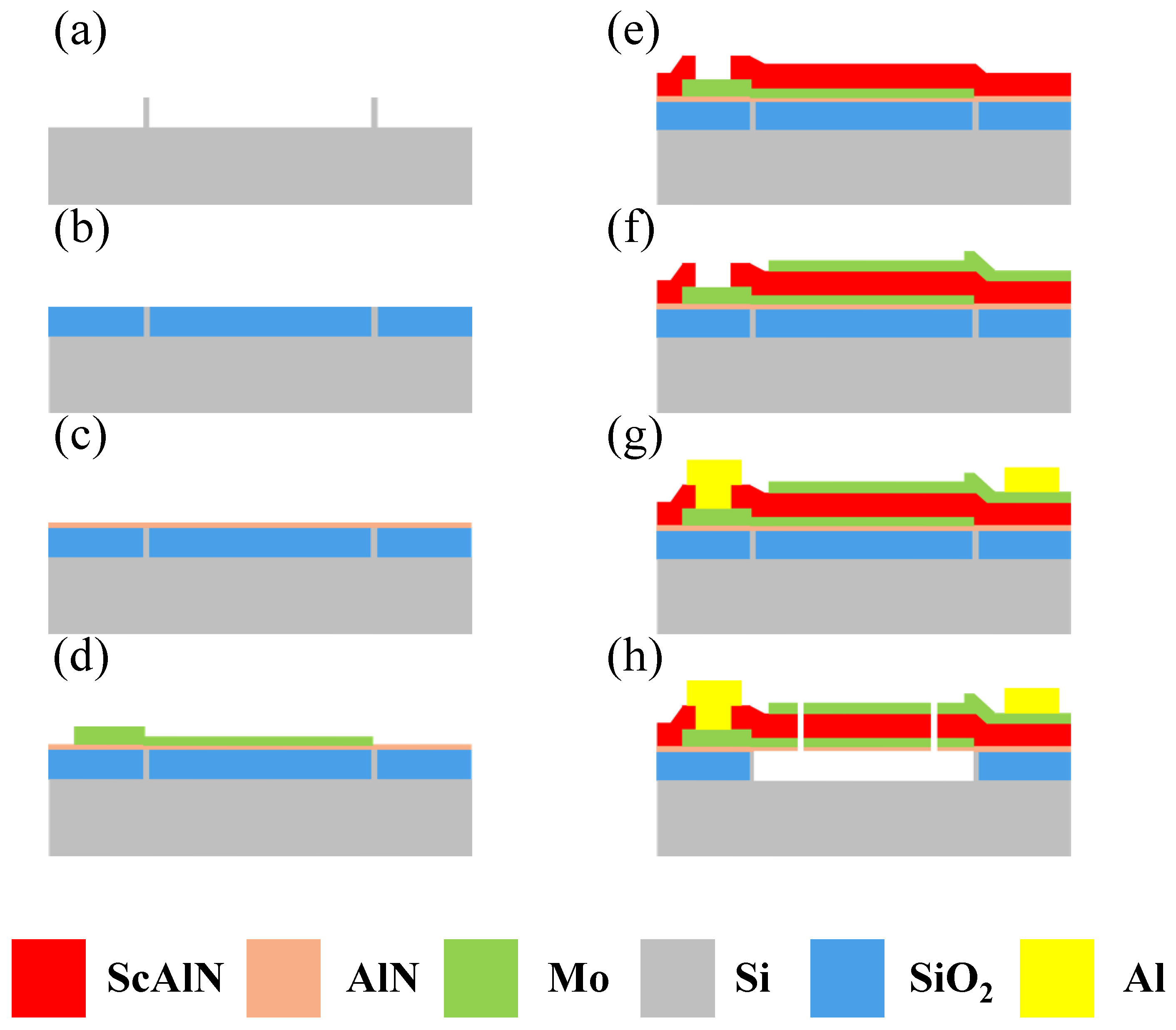
2. Design and Fabrication

We chose piezoelectric film bulk acoustic devices to construct a 5G mid-band (3.4–3.6 GHz) filter with a center frequency of 3.5 GHz. The designed piezoelectric film bulk acoustic resonator is illustrated in Figure 1. The FBAR consists of a sandwich structure with a piezoelectric layer between the top electrode and bottom electrode (TE and BE, respectively). The electrical field between the two electrodes excites the bulk acoustic wave. As shown in Figure 1b, an air cavity is created between the bottom electrode and the substrate to trap the acoustic wave between the electrodes. Figure 1c shows the working principle of the filter based on FBARs. Each resonator in this filter has two resonant frequencies. One is the series resonant frequency fs, at which the impedance can be very low (Zmin), and the other one is a parallel resonant or anti-resonant frequency fp, at which the impedance can be very high (Zmax). The parallel resonator in the filter is tuned to be worked at a slightly lower frequency, compared to the series resonator, by adding a mass-loading layer on the top electrode. When fp2, representing the parallel resonant frequency of the parallel resonators, is equal to or slightly lower than fs1, representing the series resonant frequency of the series resonators, a passband is formed between the frequencies near fs2 and fp1. As shown in Figure 1c, at the frequency point f1, the parallel FBAR can be regarded as a short-circuit state, and the signal cannot be passed to the output port. Hence, the f1 is the left transmission zero point of the filter. For the frequency point f2, the impedance of the series FBAR is small enough, while the impedance of the parallel FBAR is very large. The circuit is manifested as a channel state, and the signals are basically transmitted to the output port. At the frequency point of f3, the series FBAR can be regarded as being in a disconnection state, and the signal cannot pass the output port. Therefore, the f3 is the correct transmission zero point of the filter. For the design of the 5G mid-band (3.4–3.6 GHz) filter with a center frequency of 3.5 GHz, we used the Mason model [30,31,32] to simulate the transmit characteristics of filters. The effective electromechanical coupling coefficient ( K e f f 2 ) of FBAR calculated by Equation (1) should reach a value of about 12% [33,34], which is suitable for the band-pass width of a 5G mid-band (3.4–3.6 GHz) filter. According to the requirements of FBARs, Sc0.2Al0.8N piezoelectric thin film should be a functional piezoelectric material, and the designed thickness of each layer is shown in Table 1.
k e f f 2 = π 2 4 f s f p f p f s f p
The FBAR devices were manufactured in an eight-inch wafer, as shown in Figure 2. First, high-resistivity silicon was etched to form the separation walls; these are used to accurately define the cavity and prevent over-etching from damaging the devices. Next, the cavity was filled with SiO2, and the excess sacrificial layer was removed using chemical mechanical polishing. Then, an AlN seed layer was deposited as a buffer layer, and the Mo bottom electrode was dual-deposited and patterned. Subsequently, 500 nm thick Sc0.2Al0.8N film was reactively sputtered. Then, a 100 nm thick top Mo electrode and a 37 nm thick Mo mass-loading layer were deposited and patterned above the structure. Subsequently, 1 μm thick Al was deposited by magnetron sputtering and patterned to define the probing pads. Finally, the cavity filled with SiO2 was opened by using inductively coupled plasma (ICP) etching, and then the hydrofluoric acid vapor release cavity was introduced.

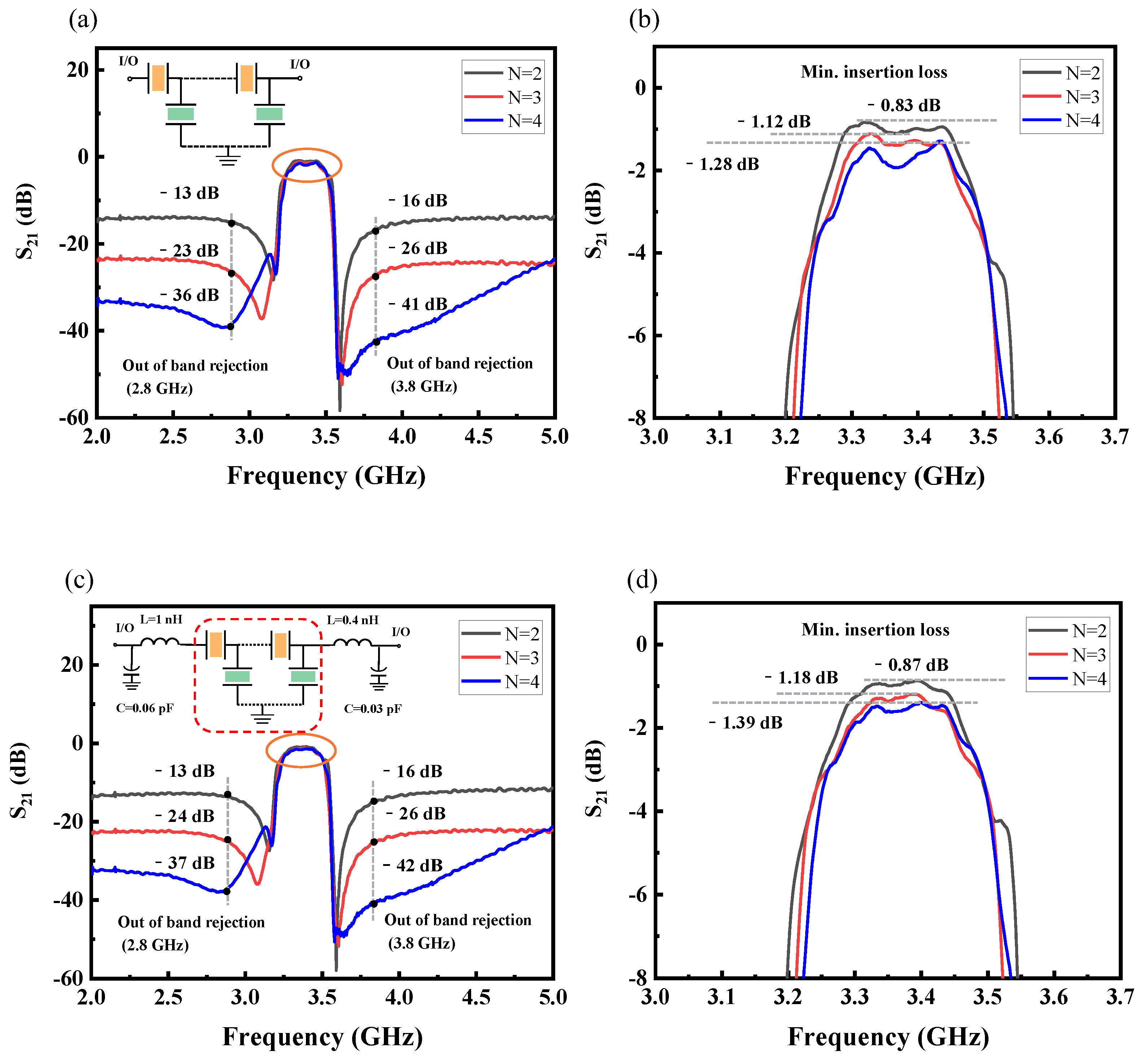
3. Results and Discussions

Sc0.2Al0.8N piezoelectric thin films were prepared by magnetron sputtering (SPTS, Sigma fxP system, Newport, UK) with a 20 at.% doped ScAl alloy target. A sputter power of 6 kW and bias power of 160 W were used for the film deposition, under a substrate temperature of 200 °C, with flow rates of N2 and Ar of 60 sccm and 20 sccm, respectively. The surface morphology of the as-deposited film was observed by using scanning electron microscope (SEM) as shown in Figure 3a, and it was found that a small amount of Sc precipitated on the surface of the as-deposited piezoelectric films. The concentration of doped Sc in the marked area of Figure 3a was tested as 21.8 at.% using energy-dispersive X-ray spectroscopy. The morphology of the Sc0.2Al0.8N piezoelectric thin film, measured by atomic force microscopy, is shown in Figure 3b, along with the corresponding Rq surface roughness value of 9.8 nm. The results of X-ray diffraction (XRD) testing of the Sc0.2Al0.8N piezoelectric thin films are shown in Figure 3c, and the corresponding diffraction angle of the Sc0.2Al0.8N (002) peak is 2θ = 36°, which corresponds to the (002) orientation. The inset shows the rocking curve of the Sc0.2Al0.8N piezoelectric film, and the full width at half maximum (FWHM) of the rocking curve is 1.73°, indicating that the piezoelectric film has a good c-axis orientation.
Figure 4a shows the optical view of the fabricated FBAR. The structure in the middle part of the figure is the resonant region, which is the main operating region of the FBAR. On each side of the resonant region are Mo anchors linked to each other with test ports. Release holes are retained around the resonance area. The space below the resonance region is released through the release holes to form a cavity. A cross-sectional view of the resonant region is shown in Figure 4b. The growth of the different material films can be clearly identified from the figure. The piezoelectric stack consists of Mo/Sc0.2Al0.8N/Mo with thicknesses of 122 nm/708 nm/186 nm, respectively, and a 27 nm thick AlN seed layer is under the bottom Mo layer. From the results of SEM inspection, it can be found that the thickness of electrodes and piezoelectric layers is different from the design. The variations in thickness may be an error generated by the machining process.
The impedance responses of series and parallel resonators, measured by a Keysight network analyzer (N5222B) connected to a Cascade Microtech GSG probe station, are shown in Figure 5. Table 2 summarizes the relevant measured and extracted parameters of the series and parallel resonators used in the filter. The quality factor (Q) of FBARs can be calculated by Equation (2) [33,35], where the τ(f) is the group delay of S11. Based on the Sc0.2Al0.8N film, the prepared resonator reached a K e f f 2 of 13.1%. However, the resonant frequency of both series and parallel resonators are lower than the designed ones shown in Figure 1b, which can be contributed to the thickness deviations of deposited electrodes and piezoelectric layers.
Q f = 2 π f τ f S 11 1 S 11 2
Figure 6a is a schematic of the ladder-type circuit design of the FBAR filter consisting of series resonators and parallel resonators. To achieve its passband transmit characteristics, an additional Mo mass-loading layer is added to the parallel resonators to make resonant frequencies lower than those of the series resonator. Figure 6b–d is the optical view of fabricated FBAR filters with different orders. Figure 6b is a second-order ladder-type FBAR filter, which includes two series resonators and two parallel resonators. Figure 6c,d show third- and fourth-order ladder-type FBAR filters, respectively.
The measured transmission responses (S21) of the FBAR filters with different orders are shown in Figure 7. Figure 7a illustrates how the out-of-band rejection gradually strengthens as the order of the filter increases. However, the insertion loss becomes worse, and the in-band ripple becomes more severe, as shown in Figure 7b. When the order of the filter is two, the out-of-band rejection is around −15 dB, and the minimum insertion loss is around −1 dB. For the fourth-order filter, the low-frequency out-of-band rejection is below −30 dB. Though the high-frequency out-of-band rejection reduces as the frequency increases, the high-frequency out-of-band rejection is still below −20 dB. The minimum insertion loss is around −1.5 dB, and the ripples are more pronounced in the fourth-order filter. What is more, consistent with the resonant performances of fabricated FBARs, the frequency ranges of the passbands of the filters are from 3.27 to 3.47 GHz, with insertion losses less than 2 dB in a 200 MHz passband range. This passband shift can be also attributed to the thicker electrodes and piezoelectric layers compared with the designed parameters [36,37]. To reduce the in-band ripple, two capacitors and two inductors were added to the circuit of the filters, as depicted in Figure 7c. The capacitances of the capacitors are 0.06 pF and 0.03 pF, and the inductances of the inductors are 1 nH and 0.4 nH, respectively. The out-of-band rejection of filters changes slightly, but the in-band ripple is reduced. The in-band interpolation loss of the fourth-order FBAR-based filter was reduced from −1.28 dB to −1.39 dB. This was mainly due to the fact that the addition of more electrical elements increases the insertion loss in the filter, resulting in a slightly lower in-band ripple. Figure 7d shows that the in-band ripple is reduced in all filters. As the filter order increases, out-of-band rejection improves but, inevitably, leads to increased insertion loss [38].

4. Conclusions

In this study, we designed ScAlN-based FBAR filters with a passband of 3.4 to 3.6 GHz for 5G mid-band frequencies and fabricated ladder-type filters with different orders. A 20 at.% Sc doping concentration was chosen to meet the requirement of K e f f 2 of 12% for FBARs, and the K e f f 2 of the fabricated Sc0.2Al0.8N-based FBARs can reach a value of 13.1%. Ladder-type filters of various orders were fabricated, and the S21 results show that the out-of-band rejection gradually strengthened as the order of the filter increased. However, the insertion loss worsens, and the in-band ripple becomes more severe. Finally, a passband from 3.27 to 3.47 GHz with a 200 MHz bandwidth and insertion loss lower than 2 dB was obtained. The achieved frequencies of the passband were lower than the designed ones due to thickness deviations during the fabrication process. With increased precision in the thickness control for the film deposition and external circuit element matching, the proposed FBAR filters can be a potential choice for application in the 5G mid-band spectrum.

Author Contributions

Conceptualization, Y.C. and C.S.; Methodology, Y.L.; Software, Y.Z. (Yu Zhou), Y.Z. (Yupeng Zheng), Y.R., C.G. and S.G.; Formal analysis, Q.X. and Y.Q.; Investigation, X.H. and C.G.; Resources, Q.X. Data curation, Y.Z. (Yu Zhou), Y.Z. (Yupeng Zheng), Y.Q., Y.R. and X.H.; Writing—original draft, Y.Z. (Yu Zhou), Y.Z. (Yupeng Zheng) and Y.C.; Writing—review & editing, Y.Z. (Yu Zhou) and Y.C.; Visualization, C.S.; Supervision, Y.L.; Funding acquisition, S.G., Y.C. and C.S. All authors have read and agreed to the published version of the manuscript.

Funding

This work was supported by the Young Scientists Fund of the National Natural Science Foundation of China under Grant No. 62204177, the National Key R&D Program of China under Grant No. 2023YFB3610103, the Fundamental Research Funds for the Central Universities under Grants 2042023kf0218 and the Open Fund of Hubei Key Laboratory of Electronic Manufacturing and Packaging Integration (Wuhan University) under Grant EMPI2023025.

Data Availability Statement

The data that support the findings of this study are available from the corresponding authors upon reasonable request.

Acknowledgments

The authors would like to thank the Core Facility of Wuhan University and the School of Power and Mechanical Engineering of Wuhan University for access to analytical equipment.

Conflicts of Interest

The authors declare no conflicts of interest.

References

  1. Yang, K.; He, C.; Fang, J.; Cui, X.; Sun, H.; Yang, Y.; Zuo, C. Advanced RF filters for wireless communications. Chip 2023, 2, 100058. [Google Scholar] [CrossRef]
  2. Lv, L.; Shuai, Y.; Luo, W.; Wu, C.; Zhang, W. Simulation of Wide Band BAW Filter for N78 Application. J. Phys. Conf. Ser. 2022, 2173, 012014. [Google Scholar] [CrossRef]
  3. Chauhan, V.; Huck, C.; Frank, A.; Akstaller, W.; Weigel, R.; Hagelauer, A. Enhancing RF bulk acoustic wave devices: Multiphysical modeling and performance. IEEE Microw. Mag. 2019, 20, 56–70. [Google Scholar] [CrossRef]
  4. Ruby, R.C.; Bradley, P.; Oshmyansky, Y.; Chien, A.; Larson, J.D. Thin film bulk wave acoustic resonators (FBAR) for wireless applications. In Proceedings of the 2001 IEEE Ultrasonics Symposium. Proceedings. An International Symposium (Cat. No. 01CH37263), Atlanta, GA, USA, 7–10 October 2001. [Google Scholar]
  5. Takai, T.; Iwamoto, H.; Takamine, Y.; Wada, T.; Hiramoto, M.; Koshino, M.; Nakajima, N. Investigations on design technologies for SAW quadplexer with narrow duplex gap. In Proceedings of the 2016 IEEE Mtt-S International Microwave Symposium (IMS), San Francisco, CA, USA, 22–27 May 2016; pp. 1–4. [Google Scholar]
  6. Dubois, M.A.; Billard, C.; Muller, C.; Parat, G.; Vincent, P. Integration of high-Q BAW resonators and filters above IC. In Proceedings of the ISSCC. 2005 IEEE International Digest of Technical Papers. Solid-State Circuits Conference, San Francisco, CA, USA, 10 February 2005; pp. 392–606. [Google Scholar]
  7. Liu, Y.; Cai, Y.; Zhang, Y.; Tovstopyat, A.; Liu, S.; Sun, C. Materials, design, and characteristics of bulk acoustic wave resonator: A review. Micromachines 2020, 11, 630. [Google Scholar] [CrossRef] [PubMed]
  8. Ou, Y.C.; Rebeiz, G.M. Lumped-element fully tunable bandstop filters for cognitive radio applications. IEEE Trans. Microw. Theory Tech. 2011, 59, 2461–2468. [Google Scholar] [CrossRef]
  9. Nishihara, T.; Yokoyama, T.; Miyashita, T.; Satoh, Y. High performance and miniature thin film bulk acoustic wave filters for 5 GHz. In Proceedings of the 2002 IEEE Ultrasonics Symposium, 2002. Proceedings, Munich, Germany, 8–11 October 2002; Volume 1, pp. 969–972. [Google Scholar]
  10. Ruppel, C.C. Acoustic wave filter technology—A review. IEEE Trans. Ultrason. Ferroelectr. Freq. Control 2017, 64, 1390–1400. [Google Scholar] [CrossRef] [PubMed]
  11. Aigner, R. SAW and BAW technologies for RF filter applications: A review of the relative strengths and weaknesses. In Proceedings of the 2008 IEEE Ultrasonics Symposium, Beijing, China, 2–5 November 2008; pp. 582–589. [Google Scholar]
  12. Wang, N.; Zhu, Y.; Chua, G.L.; Chen, B.; Merugu, S.; Singh, N.; Gu, Y. Over 10% Keff2 of demonstrated by 2-GHz spurious mode-free Sc0.12Al0.88N laterally coupled alternating thickness mode resonators. IEEE Electron Device Lett. 2019, 40, 957–960. [Google Scholar] [CrossRef]
  13. Wong, Y.P.; He, Y.; Matsuoka, N.; Liang, Q.; Bao, J.; Hashimoto, K.Y. IHP SAW transverse edge design for energy confinement with suppressed scattering loss and transverse mode. In Proceedings of the 2021 IEEE International Ultrasonics Symposium (IUS), Xi’an, China, 11–16 September 2021; pp. 1–4. [Google Scholar]
  14. Takai, T.; Iwamoto, H.; Takamine, Y.; Fuyutsume, T.; Nakao, T.; Hiramoto, M.; Toi, T.; Koshino, M. IHP SAW technology and its application to microacoustic components. In Proceedings of the 2017 IEEE International Ultrasonics Symposium (IUS), Washington, DC, USA, 6–9 September 2017; pp. 1–8. [Google Scholar]
  15. Takamine, Y.; Takai, T.; Iwamoto, H.; Nakao, T.; Koshino, M. A novel 3.5 GHz low-loss bandpass filter using IHP SAW resonators. In Proceedings of the 2018 Asia-Pacific Microwave Conference (APMC), Kyoto, Japan, 6–9 November 2018; pp. 1342–1344. [Google Scholar]
  16. Nguyen, N.; Johannessen, A.; Rooth, S.; Hanke, U. A Design Approach for High-Q FBARs with a Dual Step Frame. IEEE Trans. Ultrason. Ferroelectr. Freq. Control 2018, 65, 1717–1725. [Google Scholar] [CrossRef] [PubMed]
  17. Zhou, J.; Liu, Y.; Xu, Q.; Xie, Y.; Cai, Y.; Liu, J.; Liu, W.; Tovstopyat, A.; Sun, C. ScAlN/AlN film-based Lamé mode resonator with high effective electromechanical coupling coefficient. J. Microelectromech. Syst. 2021, 30, 677–679. [Google Scholar] [CrossRef]
  18. Mandal, D.; Banerjee, S. Surface acoustic wave (SAW) sensors: Physics, materials, and applications. Sensors 2022, 22, 820. [Google Scholar] [CrossRef]
  19. Lam, C.S. A review of the timing and filtering technologies in smartphones. In Proceedings of the 2016 IEEE International Frequency Control Symposium (IFCS), New Orleans, LA, USA, 9–12 May 2016; pp. 1–6. [Google Scholar]
  20. Li, M.; Xie, J.; Chen, B.; Wang, N.; Zhu, Y. Microstructural evolution of the abnormal crystallite grains in sputtered ScAlN film for piezo-MEMS applications. In Proceedings of the 2019 IEEE International Ultrasonics Symposium (IUS), Glasgow, UK, 6–9 October 2019; pp. 1124–1126. [Google Scholar]
  21. Nam, S.; Peng, W.; Wang, P.; Wang, D.; Mi, Z.; Mortazawi, A. An mm-wave trilayer AlN/ScAlN/AlN higher order mode FBAR. IEEE Microw. Wirel. Technol. Lett. 2023, 33, 803–806. [Google Scholar] [CrossRef]
  22. Ambacher, O.; Christian, B.; Feil, N.; Urban, D.F.; Elsässer, C.; Prescher, M.; Kirste, L. Wurtzite ScAlN, InAlN, and GaAlN crystals, a comparison of structural, elastic, dielectric, and piezoelectric properties. J. Appl. Phys. 2021, 130, 045102. [Google Scholar] [CrossRef]
  23. Gao, C.; Cai, Y.; Zou, Y.; Lin, B.; Yang, T.; Wang, Y.; Liu, Y.; Guo, S.; Sun, C. Investigation of thermal annealing on the characteristics of ScxAl1− XN thin films. Vacuum 2024, 219, 112669. [Google Scholar] [CrossRef]
  24. Li, M.; Chen, B.; Xie, J.; Song, W.; Zhu, Y. Effects of post-annealing on texture evolution of sputtered ScAlN films. In Proceedings of the 2020 IEEE International Ultrasonics Symposium (IUS), Las Vegas, NV, USA, 7–11 September 2020; pp. 1–3. [Google Scholar]
  25. Zou, Y.; Gao, C.; Zhou, J.; Liu, Y.; Xu, Q.; Qu, Y.; Liu, W.; Soon, J.B.W.; Cai, Y.; Sun, C. Aluminum scandium nitride thin-film bulk acoustic resonators for 5G wideband applications. Microsyst. Nanoeng. 2022, 8, 124. [Google Scholar] [CrossRef] [PubMed]
  26. Giribaldi, G.; Simeoni, P.; Colombo, L.; Rinaldi, M. High-Crystallinity 30% Scaln Enabling High Figure of Merit X-Band Microacoustic Resonators for Mid-Band 6G. In Proceedings of the 2023 IEEE 36th International Conference on Micro Electro Mechanical Systems (MEMS), Munich, Germany, 15–19 January 2023; pp. 169–172. [Google Scholar]
  27. Moreira, M.; Bjurström, J.; Katardjev, I.; Yantchev, V. Aluminum scandium nitride thin-film bulk acoustic resonators for wide band applications. Vacuum 2011, 86, 23–26. [Google Scholar] [CrossRef]
  28. Ding, R.; Xuan, W.; Dong, S.; Zhang, B.; Gao, F.; Liu, G.; Zhang, Z.; Jin, H.; Luo, J. The 3.4 GHz BAW RF filter based on single crystal AlN resonator for 5G application. Nanomaterials 2022, 12, 3082. [Google Scholar] [CrossRef] [PubMed]
  29. Yang, Q.; Xu, Y.; Wu, Y.; Wang, W.; Lai, Z. A 3.4–3.6 GHz high-selectivity filter chip based on film bulk acoustic resonator technology. Electronics 2023, 12, 1056. [Google Scholar] [CrossRef]
  30. Iwata, N.; Kinoshita, S.; Yanagitani, T. Extracting mechanical Q factor of the pure AlN, ScAlN, and ZnO films without etching substrate. In Proceedings of the 2020 IEEE International Ultrasonics Symposium (IUS), Las Vegas, NV, USA, 7–11 September 2020; pp. 1–2. [Google Scholar]
  31. Jamneala, T.; Bradley, P.; Koelle, U.B.; Chien, A. Modified Mason model for bulk acoustic wave resonators. IEEE Trans. Ultrason. Ferroelectr. Freq. Control 2008, 55, 2025–2029. [Google Scholar] [CrossRef]
  32. Xu, L.; Wu, X.; Zeng, Y. Simulation and research of piezoelectric film bulk acoustic resonator based on mason model. In Proceedings of the 2021 6th International Conference on Integrated Circuits and Microsystems (ICICM), Nanjing, China, 22–24 October 2021; pp. 184–188. [Google Scholar]
  33. Bi, F.Z.; Barber, B.P. Bulk acoustic wave RF technology. IEEE Microw. Mag. 2008, 9, 65–80. [Google Scholar] [CrossRef]
  34. Fattinger, G.G.; Marksteiner, S.; Kaitila, J.; Aigner, R. Optimization of acoustic dispersion for high performance thin film BAW resonators. IEEE Ultrason. Symp. 2005, 2, 1175–1178. [Google Scholar]
  35. Zou, Y.; Cai, Y.; Gao, C.; Luo, T.; Liu, Y.; Xu, Q.; Wang, Y.; Nian, L.; Liu, W.; Soon, J.B.W.; et al. Design, fabrication, and characterization of aluminum scandium nitride-based thin film bulk acoustic wave filter. J. Microelectromech. Syst. 2023, 32, 263–270. [Google Scholar] [CrossRef]
  36. Sung, P.H.; Fang, C.M.; Chang, P.Z.; Chin, Y.C.; Chen, P.Y. The method for integrating FBAR with circuitry on CMOS chip. In Proceedings of the 2004 IEEE International Frequency Control Symposium and Exposition, Montreal, QC, Canada, 23–27 August 2004; pp. 562–565. [Google Scholar]
  37. Gao, Y.; Wen, S.W.; Han, C.; Zhang, D.P. A method determining order of BAW ladder-type filter. In Proceedings of the Emerging Imaging and Sensing Technologies for Security and Defence III; and Unmanned Sensors, Systems, and Countermeasures, Berlin, Germany, 4 October 2018; Volume 10799, pp. 112–118. [Google Scholar]
  38. Bhadauria, A.; Panchal, B.; Varghese, S. RF bandpass filters using FBAR with fractal electrodes. In Proceedings of the 2018 IEEE MTT-S International Microwave and RF Conference (IMaRC), Kolkata, India, 28–30 November 2018; pp. 1–3. [Google Scholar]
Figure 1. Structures of FBAR and characteristics of filters. (a) Schematic drawing of a typical FBAR. (b) The cross-sectional view of FBAR. (c) Working principle of filter based on FBARs in the circuits model.
Micromachines 15 00563 g001
Figure 2. Fabrication of the Sc0.2Al0.8N-based FBARs. (a) The film structure of FBAR. (b) Forming separation walls. (c) SiO2 deposition and chemical mechanical polishing. (d) Seed layer deposition. (e) Bottom Mo and Sc0.2Al0.8N layers were dual-deposited and then patterned. (f) Top Mo was dual-deposited and then patterned. (g) Al was deposited and then patterned. (h) Opening the release window and release.
Micromachines 15 00563 g002
Figure 3. Characterization of the prepared Sc0.2Al0.8N piezoelectric thin film material. (a) The surface morphology observed by SEM. (b) The surface morphology observed by AFM. (c) XRD results of Sc0.2Al0.8N.
Micromachines 15 00563 g003
Figure 4. Characteristics of fabricated FBARs. (a) SEM image of top view of the fabricated FBAR resonator. (b) SEM image of the cross-sectional view of the fabricated FBAR resonator.
Micromachines 15 00563 g004
Figure 5. Measured impedance response of series and parallel resonators.
Micromachines 15 00563 g005
Figure 6. FBAR filters with different topological structures. (a) Schematic circuit designs of the FBAR filter. (bd) Second-, third- and fourth-order ladder-type FBAR filters, respectively.
Micromachines 15 00563 g006
Figure 7. Measured transmission responses (S21) of the fabricated FBAR filters. (a) The S21 responses of the filters with different orders. (b) The enlarged view of the passband in (a). (c) The S21 responses of the filters in (a) with the external circuit compensation. (d) The enlarged view of the passband in (c).
Micromachines 15 00563 g007
Table 1. The parameters of FBAR.
LayerThickness (nm)
Mo TE100
Mo massloading18
Sc0.2Al0.8N700
Mo BE150
AlN seed25
Cavity2000
Table 2. The fabricated resonators used for the FBAR filter.
ResonatorC0 (pF)fs (GHz)fp (GHz)QsQp K eff 2 (%)
Series1.143.3903.5869919313.1%
Parallel1.413.1613.35110222913.5%
Disclaimer/Publisher’s Note: The statements, opinions and data contained in all publications are solely those of the individual author(s) and contributor(s) and not of MDPI and/or the editor(s). MDPI and/or the editor(s) disclaim responsibility for any injury to people or property resulting from any ideas, methods, instructions or products referred to in the content.

