
The ARGOS Instrument for Stratospheric Aerosol Measurements


1
Science Systems and Applications, Inc., 10210 Greenbelt Road, Lanham, MD 20706, USA
2
NASA Goddard Space Flight Center, 8800 Greenbelt Road, Greenbelt, MD 20771, USA
*
Author to whom correspondence should be addressed.
Remote Sens. 2024, 16(9), 1531; https://0-doi-org.brum.beds.ac.uk/10.3390/rs16091531
Submission received: 26 March 2024
/
Revised: 22 April 2024
/
Accepted: 23 April 2024
/
Published: 26 April 2024
(This article belongs to the Special Issue Recent Developments in Remote Sensing Instruments, Technologies, and Results for Aerosol and Cloud Measurements)
Abstract
:Atmospheric aerosols represent an important component of the Earth’s climate system because they can contribute both positive and negative forcing to the energy budget. We are developing the Aerosol Radiometer for Global Observations of the Stratosphere (ARGOS) instrument to provide improved measurements of stratospheric aerosols in a compact package. ARGOS makes limb scattering measurements from space in eight directions simultaneously, using two near-IR wavelengths for each viewing direction. The combination of forward and backward scattering views along the orbit track gives additional information to constrain the aerosol phase function and size distribution. Cross-track views provide expanded spatial coverage. ARGOS will have a demonstration flight through a hosted payload provider in the fall of 2024. The instrument has completed pre-launch environmental testing and radiometric characterization tests. The hosted payload approach offers advantages in size, weight, and power margins for instrument design compared to other approaches, with significant benefits in terms of reducing infrastructure requirements for the instrument team.
1. Introduction
1.1. Science Requirements
Previous IPCC reports have focused on the impact of anthropogenic aerosols in the troposphere [1]. However, there is a growing body of evidence suggesting the additional importance of aerosols in the upper troposphere and lower stratosphere (UT/LS). The lifetime of particles injected into this region can be weeks to months, which enables regional and even global spread of material injected at a single location.
Characterizing the distribution and evolution of stratospheric aerosols is an important input parameter for climate system models that need to accurately calculate atmospheric heating [2]. The long-term persistence of stratospheric aerosols over months to years, and their resulting radiative effects, impact the ability to understand climate variations on multiple time scales. The naturally produced background stratospheric aerosol is thought to provide a modest instantaneous radiative forcing of approximately −0.04 W m−2 (i.e., cooling), but perturbations by episodic volcanic and wildfire smoke injections can result in forcings an order of magnitude greater [3]. Observing and characterizing the variability and properties of the stratospheric aerosol layer is thus essential to reducing uncertainties in forcing estimates in climate models. The necessary observations that underpin model development and better constrain the impacts of these aerosols on radiative forcing are defined as “Very Important” in the most recent Earth Science Decadal Survey (science question C-5), and aerosol measurements—including vertical profiles—are a priority observable that is “essential to the overall program” for quantification of their impacts on climate forcing [4].
Proper characterization of these aerosol inputs requires altitude-resolved measurements of aerosol extinction as a key geophysical variable to initialize transport calculations. Extensive spatial sampling and good vertical resolution are also needed to capture the inhomogeneous vertical and horizontal distribution of stratospheric aerosols. Integrated measurements such as stratospheric aerosol optical depth (sAOD) represent a valuable constraint on profile observations, but do not provide the additional information about vertical distribution that is needed for proper modeling of transport effects and radiative forcing estimation. The limited number of surface observing locations for aerosols is also insufficient to fully characterize their geographic distribution, so that satellite measurements are a necessity.
Multiple observing methods (e.g., occultation, lidar, limb scattering) can be used to monitor stratospheric aerosols from space.
- Solar occultation measurements determine total extinction directly, but only sample a single latitude each day with either sunrise or sunset events. An inclined (but not sun-synchronous) orbit is necessary to measure at different latitudes, and it may take several months to cover the full latitude range available from a given orbit.
- Space-based backscatter lidar measurements provide better spatial and temporal sampling and high vertical resolution but provide a different measured parameter (backscatter coefficient) that is not directly transferrable to the desired extinction. The low concentration of stratospheric aerosols compared to tropospheric aerosols also poses a challenge for signal-to-noise performance, particularly during daytime measurements.
- Limb scatter measurements provide comprehensive spatial and temporal sampling with daily global coverage and good vertical resolution. However, the observed signal is strongly dependent on viewing geometry (single scattering angle). In addition, the aerosol size distribution, including particle shape and composition, must be specified in order to retrieve extinction values from the measurements.
For the goal of providing an extensive dataset to give improved guidance to climate models, we feel that the limb scattering technique provides perhaps the most useful combination of vertical resolution, spatial and temporal sampling, and data quality for monitoring stratospheric aerosols.
1.2. Current Limb Scattering Measurements
Multiple instruments are currently making limb scattering measurements of stratospheric aerosols. The Optical Spectrograph and InfraRed Imaging System (OSIRIS) instrument has been operating on the Odin spacecraft since 2001 [5]. It makes measurements between 270 nm and 810 nm with 0.8 nm spectral resolution and retrieves aerosol extinction profiles at four wavelengths (470, 675, 750, 805 nm) with ~3 km vertical resolution [6]. OSIRIS flies in a near-terminator sun-synchronous orbit (0600/1800 Equator-crossing time) that limits geographic coverage during some months of the year. OSIRIS operations are currently limited in temporal coverage due to spacecraft power supply issues.
The Ozone Mapping and Profiling Suite (OMPS) Limb Profiler (LP) instrument on the Suomi NPP (S-NPP) satellite currently collects limb scattering data to create an aerosol extinction data record, which begins in 2012. A second LP instrument was launched on the NOAA-21 satellite in November 2022. The LP instrument makes hyperspectral measurements with simultaneous spectral coverage from 290 nm to 1000 nm (spectral resolution varies from 1 nm to 20 nm) and altitude coverage from 0 km to 80 km (vertical resolution ≈ 1.8 km) [7]. Three vertical slits view backward from the satellite, oriented along the orbit track and 4.25° in azimuth to each side (~250 km separation at the tangent point). Aerosol extinction profiles are retrieved at six wavelengths between 510 nm and 997 nm [8].
The viewing geometry of the LP instrument produces high scattering angles (θ ≈ 120°–160°) for Southern Hemisphere (SH) measurements, which corresponds to low phase function values for typical assumed particle size distributions [9]. In contrast, LP measurements in the Northern Hemisphere (NH) occur with forward scattering geometry (θ ≈ 20°–60°), with larger phase function values. Since the signal observed by LP is the product of the scattered radiance and phase function, SH observations can have signals 10-30 times smaller than NH observations for the same aerosol conditions, resulting in a correspondingly lower sensitivity to aerosol loading. The sun-synchronous orbit of both LP instruments (1330 equator-crossing time) also limits the LP sampling to a single local time, with a multi-day gap between revisit times at any location.
Our objective is to supplement the OMPS LP measurements by developing a simplified, compact instrument configuration focused on stratospheric aerosol observations. The Aerosol Radiometer for Global Observations of the Stratosphere (ARGOS) design also utilizes the limb scattering technique and adds multiple simultaneous viewing directions to increase spatial sampling (Figure 1) and reduce hemispheric phase function sampling sensitivity.
The viewing geometry of the ARGOS instrument enables locations along the satellite orbit track to be sampled with both forward and backward scattering view angles within approximately 15 min throughout the orbit. This approach gives a more balanced distribution of sensitivity to aerosols at all latitudes in both hemispheres. The complementary measurements collected by ARGOS at multiple scattering angles will also provide substantial statistical leverage to constrain the phase function (and thus particle size distribution) that characterizes aerosols at a given location.
2. Materials and Methods
2.1. Instrument Design
NASA’s Earth Science Technology Office (ESTO) has supported the development of ARGOS through the In-space Validation of Earth Science Technology (InVEST) program to provide improved aerosol measurements in a compact package. We adapt a design proposed by [10] to observe radiance profiles on the atmospheric limb in multiple directions simultaneously. Our initial laboratory system used a hyperbolic central mirror to redirect all incoming signals to a single focal plane that would capture the profiles, with closely spaced pixels providing altitude sampling. However, initial testing of this system revealed that the slit images it produced were not focused sufficiently for our requirements. We, therefore, revised the design to use a central mirror with multiple flat facets, which direct light from each aperture onto a specific section of the focal plane [11]. The Multi-Angle Stratospheric Aerosol Radiometer (MASTAR), with the same basic optical design as ARGOS but different wavelength selection, was built and successfully operated on a building roof at NASA Goddard Space Flight Center (GSFC) in March 2019 (Figure 2). The central mirror was revised to use a flat-sided prism shape. This change enabled better control of the optical design (because the facet angle could be precisely specified), and simplified fabrication requirements for such a small component (16 mm overall diameter).
Analysis of MASTAR field measurements yielded valuable information about instrument performance, in particular stray light characteristics, that has guided the development of the ARGOS instrument design. The original MASTAR optical design included focusing lenses in the optical path following the mirror redirection of the incoming beam, in order to produce a focused slit image on the detector. However, laboratory testing revealed the presence of stray light ghosts on the focal plane resulting from internal reflections in this design. We, therefore, revised the design to remove these lenses and place the slit plate very close to the focal plane (0.5 mm separation). This change removed the stray light path and had the additional benefits of making the overall system both mechanically simpler (fewer individual elements for each optical path) and more compact (lower overall height).
The choice of wavelengths for the ARGOS instrument has also changed through successive iterations of the design. Near-infrared wavelengths are preferred for limb scattering measurements of stratospheric aerosols because the Rayleigh scattering component of the signal decreases rapidly at longer wavelengths, enabling better sensitivity in the UT/LS region of the atmosphere. Limb scattering measurements also require very accurate instrument pointing knowledge because of the long viewing path between the satellite and the tangent point. A pointing error of 1 arc-minute (0.016°) in the pitch direction corresponds to an error of approximately 1 km in altitude registration at the tangent point. The MASTAR instrument was designed with a Cubesat-sized host vehicle in mind. When this design was first developed, small satellite buses typically could not guarantee this level of pointing knowledge. However, additional information about limb viewing altitude registration can be obtained by making measurements at a near-UV wavelength (e.g., 350 nm) and using the Rayleigh scattering attitude sensing (RSAS) technique to characterize the instrument pointing [12]. This method has been used to assess the accuracy of the operational Suomi NPP OMPS LP instrument [13].
Therefore, the MASTAR design included two orthogonal viewing directions dedicated to 350 nm measurements, as shown in Figure 2. Commercially available CCDs with adequate radiometric sensitivity at 350 nm had limited response beyond the visible region, so wavelengths of 675 nm and 850 nm were chosen for MASTAR as the longest options that also provide heritage with the OMPS LP instrument. The use of a hosted payload provider (see Section 3) for the demonstration flight of the ARGOS instrument enabled us to revise this selection. Flying on a larger satellite bus with a high-quality attitude control system allows us to remove the requirement for RSAS measurement capabilities, which in turn allows the selection of a detector with better sensitivity in the near-IR region. Thus, while we still want to maintain consistency in wavelength selection with previous instruments for validation purposes, we have shifted our choices to 870 nm and 1550 nm to improve the scientific value of the ARGOS measurements. Table 1 gives a summary of key ARGOS specifications.
Figure 3 shows a cross-section view of the optical design. Each aperture measures radiance profiles at two near-IR wavelengths (870 nm, 1550 nm) simultaneously. These wavelengths have been selected for heritage with previous aerosol measurements (OMPS LP, SAGE II and III) to get altitude coverage in the UT/LS region. The spectral separation between wavelengths and the use of the 1550 nm channel provides key information for characterization of particle size distribution [14]. The two slits in each aperture are separated by 1° in azimuth, corresponding to ~45 km at the tangent point for the planned orbit altitude of 550 km. Each aperture is pointed downward at ~22.57° from the spacecraft lower deck to align the slits on the Earth’s limb. Each vertical slit (1.3° in height) is sized to cover the altitude range −10 km to +50 km on the limb at this orbit altitude. This extended range (relative to the extent of the stratosphere) allows for variations in spacecraft altitude due to the oblateness of the Earth, which directly impacts the location of the ARGOS slits on the limb.
The limited budget and tight schedule of the InVEST program supporting ARGOS development has limited our opportunities to carry out an integrated structural–thermal–optical performance (STOP) analysis. However, the performance of the telescopes as a function of bulk temperature and pressure was evaluated with Ansys Zemax software, and the telescope materials were optimized to minimize thermal defocus effects. Simplified finite element analysis of instrument heat flow was also performed. In addition, the ARGOS instrument environmental performance was evaluated during thermal vacuum testing.
The compact design of ARGOS (20 cm across, 11 cm height) reduces the number of optical elements by placing the slit plate (below the central mirror) very close to the focal plane (0.5 mm separation), avoiding the need for secondary optical elements to focus each slit image. We obtained diffraction-limited images at each slit. Stray light control is important for ARGOS because of the potential for contributions from a variety of sources, both internal and external to the instrument. We used TracePro software to thoroughly analyze the optical design and identify mitigation approaches for these contributions. We also collected experimental data to verify the success of these approaches.
- Out of field stray light is addressed by adding an external baffle to the front of each aperture.
- Interior surfaces of the baffles, telescope tubes, optical hub, and slits are coated with Acktar “Magic Black” paint to minimize stray light.
- Dual band filters are placed prior to the achromatic objective lens in each aperture to exclude out of band solar light. These filters are also rotated about their vertical (slit) axis by 1 degree to prevent ghosting signals at the same wavelength from other parts of the slit field of view (FOV).
- The facets of the central mirror are sized to minimize possible overlap of light from one facet onto a neighboring facet. A future design improvement would be to add small partitions at the facet intersections to further isolate the optical path of each facet.
- Finally, additional spectral isolation is achieved by placing a short pass edge filter (λ < 1000 nm) on the left slit and a long pass edge filter (λ > 1400 nm) on the right slit for the path of each aperture, to ensure that each slit only records light from one wavelength band. Laboratory tests show that each filter rejects approximately 99.995% of the incoming light at wavelengths outside the desired spectral range.
The ARGOS design utilizes a commercial indium gallium arsenide (InGaAs) camera (Princeton Infrared Technologies 1280 MVCAM, Monmouth Junction, NJ, USA) for efficient data collection. The only modification for flight use is to shorten the housing so that the ARGOS slit plate can be placed in close proximity to the focal plane, as noted previously. The glass window covering the focal plane is also removed at this time. The focal plane size of 1280 × 1024 pixels provides altitude sampling at ~0.4 km/pixel for a 550 km orbit. Thermal control to keep the camera at 10–20 °C during operations is provided by a single stage thermoelectric cooler with no moving parts. The operational thermal range of the camera is −10 °C to +30 °C. The thermal response of each telescope is expected to be small because the titanium tube matches the coefficient of thermal expansion (CTE) of the filter glass, and the change in index for the objective lens glass is small. The change in focus with pressure is also small.
This camera offers a robust well depth (up to 70,000 e- in 14-bit mode) and rapid frame rate (up to 100 Hz), which reduces the potential for image saturation if a bright cloud is present in the scene. ARGOS will capture individual images with a 33 msec integration time, then co-add these images over a 6 s interval to improve signal-to-noise performance for individual aerosol extinction profiles. Our instrument model predicts signal-to-noise ratios greater than 400 at 15 km and greater than 200 at 30 km with these parameters. The 6-s averaging interval gives profile spacing comparable to the NOAA-21 OMPS LP instrument. We plan to test different observing schemes in orbit, since more closely spaced profiles are useful for tomographic retrieval algorithms that give improved resolution of aerosol vertical structure at lower altitudes [15]. Since large portions of the focal plane are not illuminated for science measurements, only selected regions surrounding each pair of slits will be captured for processing, reducing data transmission requirements by approximately 70% compared to processing the full focal plane.
2.2. Science Benefits
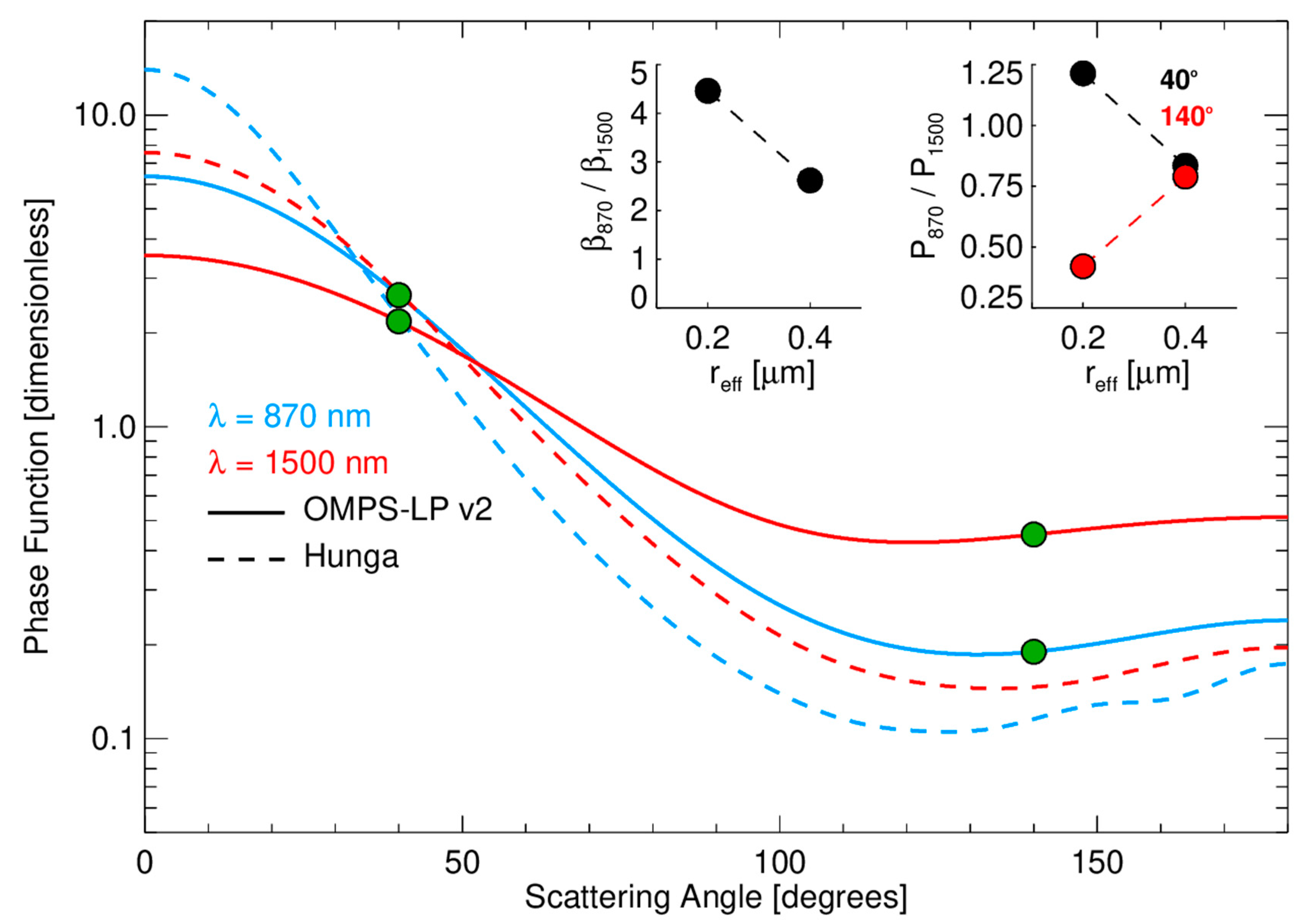
Apertures directed both forward and backward along the satellite orbit track provide the increased sensitivity of forward scattering views in both hemispheres, as well as nearly simultaneous views of single air parcels (within 15 min) that enable better characterization of the aerosol phase function. Typical aerosol phase function curves are relatively flat at backward scattering angles (θ > 90°) but increase rapidly at forward scattering angles (θ < 90°). Comparison of measurements made at different scattering angles, as well as using multiple wavelengths, will provide information that can help distinguish between phase function curves representing different particle size distribution models (Figure 4). Measurements using apertures pointed away from the orbit track will occur at scattering angles between the values shown in Figure 4 and can give additional sampling of the phase function curve if the aerosol field is regionally homogeneous.
Apertures directed at 45° and 90° azimuth to the orbit track provide expanded spatial coverage. Figure 5 illustrates the spatial location of ARGOS samples for three consecutive orbits. The sample locations for a nominal orbit N (red dots) are approximately centered in the plot. Note that the west-directed sample locations from the preceding orbit N-1 (green dots) fall very close to the along-track sample locations from orbit N. Similarly, the east-directed cross-track sample locations from the following orbit N + 1 (blue dots) also fall close to the track of orbit N. ARGOS will thus be able to look for short-term variations in aerosol behavior within each day, as well as filling spatial sampling gaps between satellite orbit tracks.
3. Implementation and Status
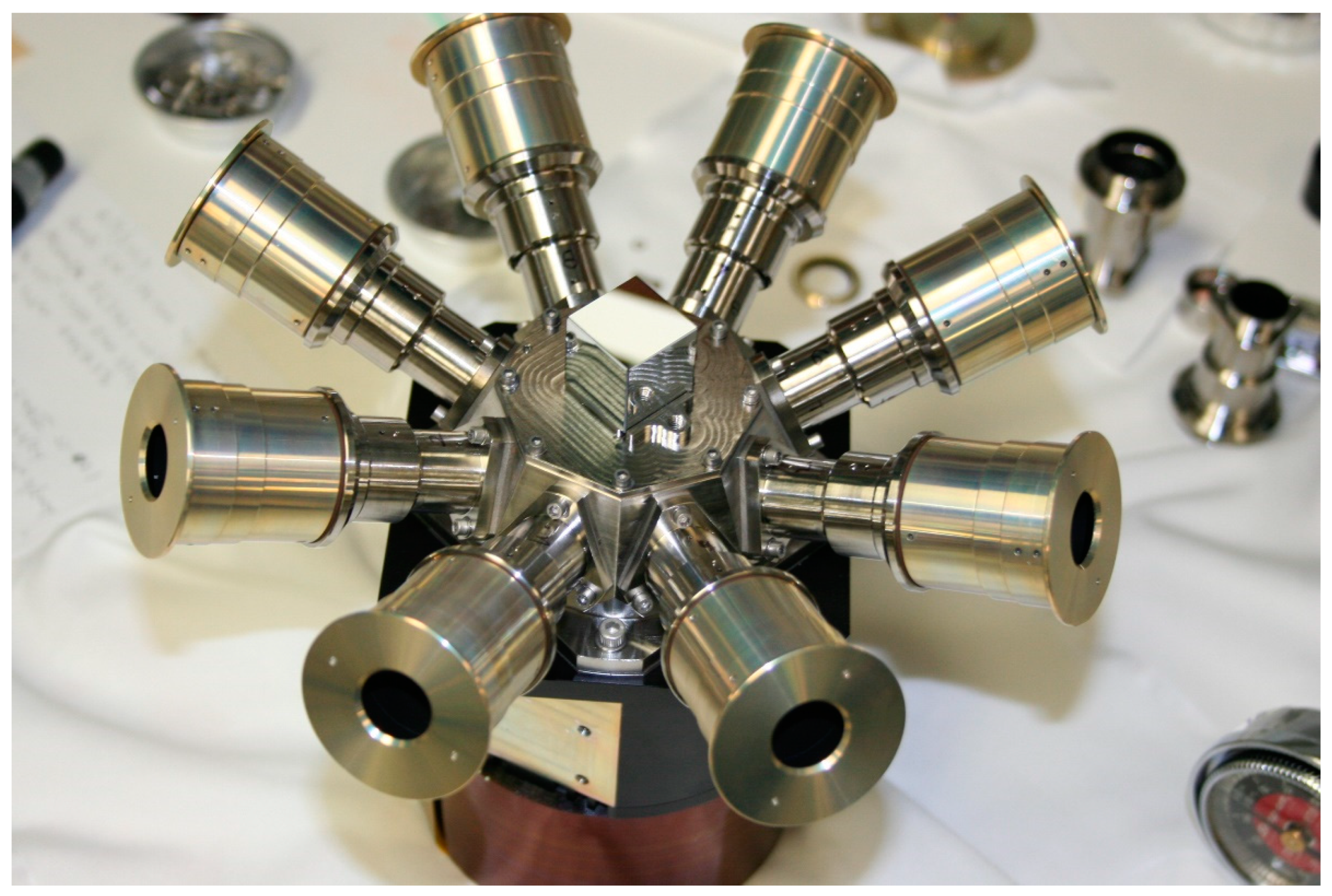
All optical and mechanical components have been delivered and integrated. Figure 6 shows the fully assembled ARGOS instrument prior to the start of environmental testing. ARGOS has successfully completed qualification-level vibration testing and thermal vacuum testing. Radiometric testing to establish performance characterization for dark current, linearity, stray light, optical alignment, and absolute calibration concluded in March 2024.
Space flight demonstration of ARGOS is planned for the fall of 2024 through NASA’s In-Space Validation of Earth Science Technologies (InVEST) program, utilizing a hosted payload provider (Loft Orbital) for the flight. This approach offers multiple advantages for our program.
- While the ARGOS design is relatively small and light, significant compromises in its configuration would be necessary to fit into a 6U Cubesat envelope. Loft’s hosted payload approach offers substantial margins in size, weight, and power for our existing design.
- Loft provides an existing spacecraft bus that supplies instrument power, thermal control, flight software, and space-to-ground communication functions. This enables our instrument team to plan for specified interfaces.
- The Loft spacecraft bus will provide the pointing knowledge (<1 arcmin over a 6-s averaging period, equivalent to <1 km accuracy in altitude registration from this orbit) required to make high-quality limb scattering measurements.
- Frequent flight opportunities are available, depending on mission requirements.
- Mission costs are defined in advance and fixed throughout the beginning of in-orbit operations, which greatly simplifies financial planning for a program with a limited budget.
The demonstration mission is planned for a sun-synchronous orbit at 550 km altitude, with the local time of ascending node (LTAN) to be determined. Our minimum duration for demonstration of instrument capability is 3 months, with the potential for extended operations. We plan to adapt the current OMPS LP aerosol retrieval algorithm [8] to create aerosol extinction coefficient products from the ARGOS measurements. This algorithm uses a radiative transfer model [16] to calculate the Rayleigh scattering background signal assuming no aerosols and normalizes the radiance profile at high altitude (38.5 km) to reduce stray light effects.
4. Discussion
The ARGOS instrument is designed to provide increased sensitivity over a wide range of latitudes and expanded spatial coverage compared to current instruments that make limb scattering measurements of stratospheric aerosols. Multiple apertures viewing the Earth’s limb at two wavelengths simultaneously, feeding incoming light into a single central optical system and focal plane, are used to accomplish these objectives. Predecessor versions of ARGOS have successfully demonstrated the design in laboratory and field measurements. The instrument size, mass, and power requirements are kept small to enable deployment on different satellite platforms. A demonstration flight of ARGOS in space is planned for the fall of 2024. The basic design of ARGOS could be adapted to measure other atmospheric constituents (e.g., water vapor) with an appropriate choice of spectral bands and focal plane.
Author Contributions
Conceptualization, M.T.D. and M.G.K.; data curation, M.T.D., M.G.K., P.R.C. and L.R.-I.; formal analysis, M.G.K., P.R.C. and L.R.-I.; funding acquisition, M.T.D. and M.G.K.; methodology, M.G.K., P.R.C. and L.R.-I.; project administration, M.T.D. and M.G.K.; resources, M.T.D. and M.G.K.; software, M.T.D., M.G.K., P.R.C. and L.R.-I.; supervision, M.T.D. and M.G.K.; validation, M.G.K. and L.R.-I.; visualization, M.T.D., M.G.K., P.R.C. and L.R.-I.; writing—original draft, M.T.D.; writing—review and editing, M.T.D., M.G.K., P.R.C. and L.R.-I. All authors have read and agreed to the published version of the manuscript.
Funding
This research was funded by the National Aeronautics and Space Administration (NASA) Earth Science Technology Office (ESTO) under grant 80NSSC21K1665.
Data Availability Statement
Data from this mission will be available from the primary author upon request.
Conflicts of Interest
Author Matthew DeLand was employed by Science Systems and Applications, Inc. The remaining authors declare that the research was conducted in the absence of any commercial or financial relationships that could be construed as a potential conflict of interest.
References
- Masson-Delmotte, V.; Zhai, P.; Pirani, A.; Connors, S.L.; Péan, C.; Berger, S.; Caud, N.; Chen, Y.; Goldfarb, L.; Gomis, M.I.; et al. (Eds.) Climate Change 2021: The Physical Science Basis. Contribution of Working Group I to the Sixth Assessment Report of the Intergovernmental Panel on Climate Change; IPCC, Cambridge University Press: Cambridge, UK; New York, NY, USA, 2021; p. 2391. [Google Scholar] [CrossRef]
- Kremser, S.; Thomason, L.W.; von Hobe, M.; Hermann, M.; Deshler, T.; Timmreck, C.; Toohey, M.; Stenke, A.; Schwarz, J.P.; Weigel, R.; et al. Stratospheric aerosol—Observations, processes, and impact on climate. Rev. Geophys. 2016, 54, 278–335. [Google Scholar] [CrossRef]
- Shallock, J.; Brühl, C.; Bingen, C.; Höpfner, M.; Rieger, L.; Lelieveld, J. Reconstructing volcanic radiative forcing since 1990, using a comprehensive emission inventory and spatially resolved sulfur injections from satellite data in a chemistry-climate model. Atmos. Chem. Phys. 2023, 23, 1169–1207. [Google Scholar] [CrossRef]
- National Academies of Science, Engineering, and Medicine. Thriving on Our Changing Planet: A Decadal Strategy for Earth Observation from Space; National Academies Press: Washington, DC, USA, 2018; p. 716. [Google Scholar] [CrossRef]
- Llewellyn, E.J.; Lloyd, N.D.; Degenstein, D.A.; Gattinger, R.L.; Petelina, S.V.; Bourassa, A.E.; Wiensz, J.T.; Ivanov, E.V.; McDade, I.C.; Solheim, B.H.; et al. The OSIRIS instrument on the Odin spacecraft. Can. J. Phys. 2004, 82, 411–422. [Google Scholar] [CrossRef]
- Rieger, L.A.; Zawada, D.J.; Bourassa, A.E.; Degenstein, D.A. A multiwavelength retrieval approach for improved OSIRIS aerosol extinction retrievals. J. Geophys. Res. Atmos. 2019, 124, 7286–7307. [Google Scholar] [CrossRef]
- Jaross, G.; Bhartia, P.K.; Chen, G.; Kowitt, M.; Haken, M.; Chen, Z.; Xu, P.; Warner, J.; Kelly, T. OMPS Limb Profiler instrument performance assessment. J. Geophys. Res. Atmos. 2014, 119, 4399–4412. [Google Scholar] [CrossRef]
- Taha, G.; Loughman, R.; Zhu, T.; Thomason, L.; Kar, J.; Rieger, L.; Bourassa, A. OMPS LP Version 2.0 multi-wavelength aerosol extinction coefficient retrieval algorithm. Atmos. Meas. Tech. 2021, 14, 1015–1036. [Google Scholar] [CrossRef]
- Loughman, R.; Bhartia, P.K.; Chen, Z.; Xu, P.; Nyaku, E.; Taha, G. The Ozone Mapping and Profiler Suite (OMPS) Limb Profiler (LP) Version 1 aerosol extinction retrieval algorithm: Theoretical basis. Atmos. Meas. Technol. 2018, 11, 2633–2651. [Google Scholar] [CrossRef]
- Junior, V.G.; Junior, J.O. Development of an omnidirectional vision system. J. Braz. Soc. Mech. Sci. Eng. 2006, 28, 58–68. [Google Scholar] [CrossRef]
- DeLand, M.; Colarco, P.; Kowalewski, M.; Gorkavyi, N.; Ramos-Izquierdo, L. Development of the Multi-Angle Stratospheric Aerosol Radiometer (MASTAR). In Proceedings of the IGARSS 2018–2018 IEEE International Geoscience and Remote Sensing Symposium, Valencia, Spain, 22–27 July 2018; pp. 6312–6315. [Google Scholar] [CrossRef]
- Janz, S.J.; Hilsenrath, E.; Flittner, D.E.; Heath, D.F. Rayleigh scattering attitude sensor. Proc. SPIE 1996, 146, 2831. [Google Scholar] [CrossRef]
- Moy, L.; Bhartia, P.K.; Jaross, G.; Loughman, R.; Kramarova, N.; Chen, Z.; Taha, G.; Chen, G.; Xu, P. Altitude registration of limb-scattered radiation. Atmos. Meas. Technol. 2017, 10, 167–178. [Google Scholar] [CrossRef]
- Rieger, L.A.; Bourassa, A.E.; Degenstein, D.A. Stratospheric aerosol particle size in Odin-OSIRIS limb scatter spectra. Atmos. Meas. Tech. 2014, 7, 507–522. [Google Scholar] [CrossRef]
- Bourassa, A.E.; Zawada, D.J.; Rieger, L.A.; Warnock, T.W.; Toohey, M.; Degenstein, D.A. Tomographic retrievals of Hunga Tonga-Hunga Ha’apai volcanic aerosol. Geophys. Res. Lett. 2023, 50, e2022GL101978. [Google Scholar] [CrossRef]
- Loughman, R.; Flittner, D.; Nyaku, E.; Bhartia, P.K. Gauss-Seidel limb scattering (GSLS) radiative transfer model development in support of the Ozone Mapping and Profiling Suite (OMPS) limb profiler mission. Atmos. Chem. Phys. 2015, 15, 3007–3020. [Google Scholar] [CrossRef]
Figure 1.
The ARGOS instrument will view the Earth’s limb with eight apertures simultaneously. Each aperture has two slits that measure radiance profiles at separate wavelengths over the altitude range 0–60 km. The dashed line shows the sub-satellite orbit track, and the dotted line shows the nadir direction from the satellite.

Figure 2.
(Left panel): Horizon view from the top of the MASTAR instrument during field tests at NASA GSFC in March 2019. (Right panel): CCD image taken during the field test. Wavelength assignments for each slit are shown. Aperture #3 (AP3) is located on the left and viewing towards the sun (east).

Figure 3.
Cutaway view of the optical path for ARGOS. Light enters each aperture from the Earth’s limb, passes through an achromatic lens to be reflected from the central multi-faceted mirror, and then is transmitted through a slit plate onto the detector focal plane.
Figure 3.
Cutaway view of the optical path for ARGOS. Light enters each aperture from the Earth’s limb, passes through an achromatic lens to be reflected from the central multi-faceted mirror, and then is transmitted through a slit plate onto the detector focal plane.

Figure 4.
Nominal aerosol phase function curves for the wavelengths that ARGOS will use. The solid lines correspond to the particle size distribution assumed for OMPS LP retrievals (effective radius, reff = 0.19 µm) [8]. The dashed lines correspond to a candidate size distribution for aerosols injected by the Hunga Tonga Hunga Ha’apai volcanic eruption in January 2022 (reff = 0.39 µm). Green dots show scattering angles for typical ARGOS forward and backward view measurements at 40°S latitude. The separation in scattering angle between these measurements will be greater at higher latitudes, and smaller at lower latitudes. Inset figures show, respectively, the 870 nm/1500 nm extinction ratio as a function of the effective radius of the two assumed aerosol size distributions, and the 870 nm/1500 nm scattering phase function intensities as a function of the assumed size distributions at scattering angles 40 degrees (black) and 140 degrees (red).

Figure 5.
Nominal ARGOS spatial sampling. Red dots show the locations of all samples for nominal orbit N. Orange lines show view directions of all eight apertures for a single observation when the satellite is crossing the equator. Green dots show sample locations for the preceding orbit (N − 1), blue dots show sample locations for the following orbit (N + 1).

Figure 6.
Fully assembled ARGOS instrument prepared for radiometric testing. The small reference cube in the center of the hub is used for optical alignment. This image was taken before the addition of thermal blankets for flight operations.
Figure 6.
Fully assembled ARGOS instrument prepared for radiometric testing. The small reference cube in the center of the hub is used for optical alignment. This image was taken before the addition of thermal blankets for flight operations.


Table 1.
ARGOS specifications.
| Parameter | Value |
|---|---|
| Size | 20 cm [W] × 20 cm [L] × 11.3 cm [H] |
| Mass | 4.2 kg |
| Power | 12 W (nominal) |
| Apertures | 8 (each separated by 45° in azimuth) |
| Wavelengths (each aperture) | 870 (±5) nm, 1550 (±20) nm |
| Slit field of view | 1.29° [H] × 0.17° [W] |
| Slit separation (each aperture) | 1° |
| Altitude coverage | 0–50 km at 550 km orbit altitude |
| Camera | Princeton IR Technologies 1280 MVCam |
| Focal plane | 1280 × 1024 pixels |
| Data rate (with subsetting and averaging) | 2.0 Mbits/second |
| Data volume (typical) | ~13 Gbytes/day |
Disclaimer/Publisher’s Note: The statements, opinions and data contained in all publications are solely those of the individual author(s) and contributor(s) and not of MDPI and/or the editor(s). MDPI and/or the editor(s) disclaim responsibility for any injury to people or property resulting from any ideas, methods, instructions or products referred to in the content. |
© 2024 by the authors. Licensee MDPI, Basel, Switzerland. This article is an open access article distributed under the terms and conditions of the Creative Commons Attribution (CC BY) license (https://creativecommons.org/licenses/by/4.0/).
Share and Cite
MDPI and ACS Style
DeLand, M.T.; Kowalewski, M.G.; Colarco, P.R.; Ramos-Izquierdo, L. The ARGOS Instrument for Stratospheric Aerosol Measurements. Remote Sens. 2024, 16, 1531. https://0-doi-org.brum.beds.ac.uk/10.3390/rs16091531
AMA Style
DeLand MT, Kowalewski MG, Colarco PR, Ramos-Izquierdo L. The ARGOS Instrument for Stratospheric Aerosol Measurements. Remote Sensing. 2024; 16(9):1531. https://0-doi-org.brum.beds.ac.uk/10.3390/rs16091531
Chicago/Turabian StyleDeLand, Matthew T., Matthew G. Kowalewski, Peter R. Colarco, and Luis Ramos-Izquierdo. 2024. "The ARGOS Instrument for Stratospheric Aerosol Measurements" Remote Sensing 16, no. 9: 1531. https://0-doi-org.brum.beds.ac.uk/10.3390/rs16091531
Note that from the first issue of 2016, this journal uses article numbers instead of page numbers. See further details here.