Article

Research on the Mechanism of Strength Improvement in Acid–Base-Activated Low Carbon Oil Absorbent Concrete

1
College of Civil Engineering and Architecture, Northeast Petroleum University, Daqing 163318, China
2
State Key Laboratory of Metastable Materials Science and Technology, Yanshan University, Qinhuangdao 066000, China
*
Author to whom correspondence should be addressed.
Sustainability 2024, 16(9), 3661; https://0-doi-org.brum.beds.ac.uk/10.3390/su16093661
Submission received: 19 March 2024 / Revised: 11 April 2024 / Accepted: 24 April 2024 / Published: 26 April 2024
(This article belongs to the Special Issue Porous Materials for Sustainable Futures)

Abstract

:
The aim of this study is to improve the compressive strength of oil absorbent concrete (OAC) and to encourage its use in slope protection projects. This study used fly ash and slag produced in thermal power plants to substitute cement in significant amounts to prepare oil absorbent concrete (OAC). The water–cement ratios were set at 0.4, 0.5, and 0.6 and the sand rates were set at 30%, 35%, and 40% to investigate the effects of these factors on the oil absorption properties of the concrete, the variation of the oil absorption rate over time, and the compressive strengths at 28 days, 60 days, and 90 days. The compressive strength of oil absorbent concrete was improved by incorporating seashell powder (SC), alkali-modified seashell powder (SSC), and acid–base-modified seashell powder (CSC). The results showed that the optimal water–cement ratio for comprehensive oil absorption performance and compressive strength was 0.5, while the optimal sand ratio was 0.35. Compared with ordinary concrete, the oil absorption performance improved by 58.69%. The oil absorption rate decreased gradually over time. However, the oil absorption time could be effectively extended and the oil absorption performance could be improved by the addition of a silane modifier. The best method for seashell modification was acid–base modification. The compressive strength reached 14.32 Mpa at 28 days and 17.45 Mpa at 90 days, which was 19.62% higher than that of OAC. Scanning electron microscopy (SEM), mercury intrusion porosimetry (MIP), and X-ray diffraction (XRD) were used to analyze the microstructure of OAC. It was discovered that the inclusion of CSC caused a reaction with hydrocalumite in the concrete, resulting in the formation of alumohydrocalcite. Additionally, Ca(OH)2 in CSC facilitated the hydration reaction of mineral admixtures like fly ash and slag. At 28 days, more amorphous gels (C-S-H, C-(A)-S-H) and Aft were produced. The three components were combined to enhance the bonding between the cementitious materials and the aggregates, resulting in a denser internal structure of the OAC and improving its strength. This study promotes the use of OAC in slope protection projects.

1. Introduction

With the development of the economy, the problem of high energy consumption resulting from the extraction of non-renewable raw materials in the construction industry has become increasingly severe [1,2]. More than one-third of resources, such as limestone and clay, are consumed in concrete production. In addition, the production of one ton of concrete generates approximately 0.8 tons of CO2 [3]. Every year, the CO2 produced by the production of concrete accounts for about 10% of total pollution, and this proportion is showing an upward trend [4]. The current solution is to produce concrete by recycling waste, which not only improves resource utilization but also reduces CO2 emissions [5,6]. As the demand for petroleum resources by humans increases day by day, leakage accidents frequently occur in all aspects of petroleum extraction, transportation, refining, and consumption [7]. The water bodies near offshore waters and estuarine waters are polluted, which in turn is destroying the local ecological environment and affecting economic development [8]. The removal of oil pollutants from water bodies requires urgent research and solutions. Incorporating a significant amount of fly ash can build the porous structure of concrete and improve its adsorption capacity. However, this alone may not be sufficient to achieve efficient oil absorption in the concrete [9].
Hydrophobic materials can change the surface of concrete from hydrophilic to hydrophobic, thereby improving its oil absorption performance [10,11]. Hydrophobic materials are usually based on silanes and siloxanes, and hydrophobic nanosilica exhibits a hydrophobic and oil absorbent capacity through photocatalysis [12,13,14]. Studies have shown that hydrophobic materials, such as isooctyltriethoxysilane, can form silicon–hydrogen oxide bonds after hydrolysis. It combines with the hydroxyl groups on the surface of concrete to form relatively stable silicon–oxygen–silicon bonds, which exhibit good oil absorption. OAC can be prepared using a silane modifier, but it has an unstable effect on the compressive strength of concrete [15]. He et al. used a superhydrophobic coating to treat the surface of concrete with hydrophobicity. They discovered that the compressive strength of the concrete was 40.2 Mpa at 28 days, nearly identical to that of the control group [16]. This finding was similar to the research results of Hou et al. [17]. Surface modification might hinder the evaporation of water within the concrete, allowing the cementitious material to undergo a complete hydration reaction [18]. Compared with surface hydrophobic modification, overall hydrophobic modification has a greater impact on concrete strength. Feng et al. conducted an integral hydrophobic modification of the mortar by incorporating a water-borne stearic acid emulsion (SAE). The results showed that the compressive strength decreased by approximately 20% [19]. Aubert reported that when the mass content of fly ash in concrete exceeded 50%, its compressive strength decreased significantly as the porosity increased, and its compressive strength was less than 10 Mpa at 28 days [20]. The addition of a large amount of fly ash will cause the compressive strength of concrete to decrease significantly, thereby limiting the potential applications of OAC [21].
Seashell waste is a kind of potentially available solid waste in coastal cities [22]. Djobo et al. found that incorporating an optimal quantity of seashell waste powder into geopolymer could increase compressive strength by 7.78% at 28 days [23]. Research by Kuo et al. demonstrated that incorporating seashell waste into concrete as fine aggregate initially increased its compressive strength, but then decreased with higher seashell content. The optimal content was 5%, and the compressive strength could increase by 37.29% at 28 days [24]. Seashell powder, as an inert material, has weak reactivity with other cementitious materials in concrete, and its compressive strength increases due to physical filling [25,26,27].
Ruengsillapanun et al. investigated the mechanical properties of fly ash concrete by employing NaOH as an alkali activator. The results revealed that the highest compressive strength was achieved at an NaOH concentration of 6 mol/L, with the compressive strength reaching 17.1 Mpa at 28 days [28]. This demonstrates that alkaline activators, such as NaOH, could be used to improve the compressive strength of concrete when significant quantities of mineral admixtures are used [29]. Oderji et al. studied the impact of slag content and various alkali activators on the mechanical properties of geopolymers. They found that the activating effects of different types of activators were in the order of Na2SiO3 + NaOH > Na2SiO3 > NaOH [30]. Wardhono et al. used fly ash and seashell waste as raw materials and employed sodium silicate and NaOH to prepare geopolymer concrete. They found that incorporating 10% seashell waste could increase the compressive strength of fly ash-based geopolymer concrete by 9.43% at 28 days [31]. Hasnaoui et al. found that seashell powder underwent an alkali activation process, dissolving CaCO3, and producing carbonate and C-S-H gel [32]. The above researchers showed that alkaline substances had the ability to modify compressive strength. Different types of acidic solutions exhibited different rates of Ca2+ dissolution in seashell. Weak acids inhibited the formation of CaCO3 due to the hydrogen bonds between a large number of carboxyl groups [33]. Studies have found that chitin could be extracted from seashells through acid treatment and converted into chitosan through a deacetylation reaction [34]. Research by Wang et al. showed that incorporating an optimal amount of chitosan into metakaolin enhanced the compressive strength of the geopolymer. The compressive strength of the sample increased by 18.66% after 7 days when 5% chitosan was added [35]. Li et al. incorporated N-carboxymethyl chitosan into a fly ash-based polymer to increase unconfined compressive strength by 3.5% at 28 days [36]. These studies indicate that acid–base-modified seashell powder is anticipated to improve the compressive strength of OAC.
This article explored the impact of water–cement ratio and sand ratio on the strength of highly absorbent concrete. OAC prepared was by incorporating a silane modifier, fly ash, and slag. Acid–base modification treatment was applied to seashell powder in order to improve OAC compressive strength. It can enhance the value of engineering applications and contribute to green and sustainable development.

2. Experimental Methods
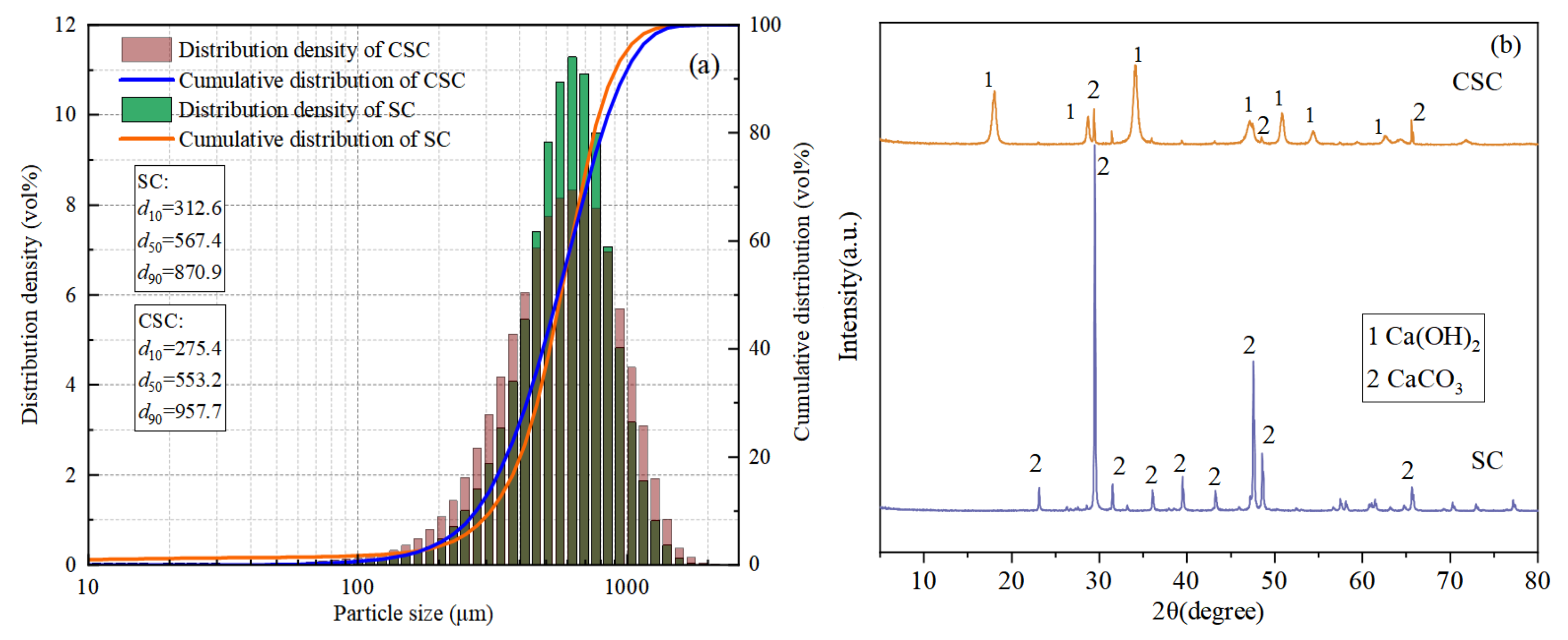
2.1. Raw Materials

P·II 42.5 Portland cement was acquired from Qinhuangdao Asano Co., Ltd. (Qinhuangdao, China). The ground granulated blast furnace slag of S95 and fly ash were produced by Qinhuangdao Suizhong Thermal Power Plant (Qinhuangdao, China), and their chemical compositions are shown in Table 1. The fine aggregate used was river sand with a fineness modulus of 2.5, and a manufactured sand with a fineness modulus of 3.48, which was a zone II coarse sand. The coarse aggregate consisted of granite gravel with a particle size range from 5 mm to 20 mm and a well-graded distribution, meeting the test requirements. Both coarse and fine aggregates were sourced from the Qinhuangdao Municipal Building Materials Group (Qinhuangdao, China) and their main physical properties are shown in Table 2. The seashells were sourced from scallop shells at the Bohai Bay scallop farm, and water was obtained from the Qinhuangdao City Waterworks (Qinhuangdao, China). This study used 96% analytically pure NaOH solid and 99% analytically pure citric acid solid. Both chemical reagents were produced by Tianjin Kaitong Chemical Reagent Co., Ltd. (Tianjin, China). Soybean oil was sourced from Yihai Kerry Arowana Grain, Oil and Food Co., Ltd. (Shanghai, China). The silane modifier was purchased from Shanxi Jingchen Building Materials Co., Ltd. (Yuncheng, China).

2.2. Sample Preparation

2.2.1. Mix Design

The preliminary research found that concrete exhibited efficient oil adsorption performance when the cementitious material ratio was 70% Class II fly ash, 10% S95 slag, and 20% P·II cement, with a silane modifier content of 3%, and a water–cement ratio of 0.5 [37,38]. In addition, the ratio used large volumes of fly ash and slag, effectively improving the reuse of mineral admixtures like fly ash, thus promoting sustainable economic development. Therefore, the above mixture proportion was used as the basis for our modified concrete design. The specific mixture proportions are shown in Table 3.

2.2.2. Preparation of Alkali-Modified Seashell Powder

Studies have shown that chitin can be extracted from seashells by modifying them, and chitosan can be prepared through the deacetylation reaction of chitin [39]. For the seashell powder, scallop shell powder with a particle size ranging from 0.3 mm to 0.6 mm was used. The processing steps are as follows:
S1.
Washed and dried the seashell waste, and then crushed and sieved them, retaining seashell powder with a particle size of 0.3–0.6 mm;
S2.
Soaked the seashell powder in a 25% NaOH solution for 3 days, then dried it at 60 °C for later use.

2.2.3. Preparation of Acid–Base-Modified Seashell Powder

For the seashell powder, scallop shell powder with a particle size ranging from 0.3 mm to 0.6 mm was used. The processing steps are as follows:
S1.
Washed and dried the seashell waste, and then crushed and sieved them, retaining seashell powder with a particle size of 0.3–0.6 mm.
S2.
Soaked the SC in a 30% citric acid solution and used an ultrasonicator (SN-QX-20D, Shanghai Shangyi Instrument Equipment Co., Ltd., Shanghai, China) to soak for 60 min. Rinsed the seashell powder with water until it was neutral.
S3.
Used an NaOH solution to treat the seashell powder three times. The procedure is as follows: First, soaked the seashell powder in a 25% NaOH solution for 30 min, then rinsed it with water until neutral. Soaked it in a 12% NaOH solution for 30 h, and rinsed it again with water until it became neutral. Soaked the material in citric acid for 4 h, then rinsed it with water until neutral. Next, soaked it in 60% NaOH for 24 h, and finally rinsed it with water until neutral.
S4.
The seashell powder was processed using a microwave by placing it in an industrial microwave oven (QX-5HO, Dongguan Qixie Microwave Equipment Co., Ltd., Dongguan, China) with a microwave power of 1180 W and a light wave power of 850 W for 60 min. Finally, the seashell powder was removed when the temperature dropped to room temperature and stored for later use.
The SC and CSC particle size distributions are shown in Figure 1a. The particle size distribution range of SC and CSC does not change much, and the particle size distribution range is mainly a unimodal distribution. The d50 of CSC (553.2 μm) is smaller than the d50 of SC (567.4 μm). The reason is that the corrosion effect during acid–base modification makes the CSC particle size smaller.
The SC and CSC XRD patterns are shown in Figure 1b. The figure showed that SC only had the diffraction peak of CaCO3, indicating that its main component was CaCO3. After undergoing acid and alkali treatment, the XRD pattern of CSC showed diffraction peaks at 2θ angles of 18°, 28°, 34°, 47°, 50°, and 54°, which was characteristic of Ca(OH)2 peaks. The diffraction peak of CaCO3 was also observed. This indicated that after acid and alkali treatment, some of the CaCO3 in SC was transformed into Ca(OH)2.

2.2.4. OAC Sample Preparation

The preparation method for OAC samples is as follows: Initially, isooctyltriethoxysilane, NaOH, and other materials were dissolved in water. Then, the cementitious materials, modified seashell powder, and fine aggregates were placed into the mixer and stirred for 30 s. Subsequently, the necessary water was added to the mixer and stirred for 50 s to obtain the mortar. Finally, the coarse aggregates were added to the mixer and stirred for 60 s.
After the concrete was prepared, it was poured into molds of 100 mm × 100 mm × 100 mm and 40 mm × 40 mm × 160 mm. The preparation was placed on a vibrating table and allowed to vibrate for 35–40 s. It was then covered with polyvinyl chloride (PVC) film, and placed indoors at 20 °C for 24 h before demolding. Then, it was placed in a curing box at (20 ± 2) °C with a relative humidity of 95% for the required time. The sample preparation process is shown in Figure 2.

2.3. Test Methods

2.3.1. Oil Adsorption and Compressive Strength Test

The aim of this study was to evaluate the adsorption performance of concrete on floating oil on the water surface, considering the high adsorption rate of soybean oil by the concrete material and the easy availability of the material. Oil adsorption experiments were conducted using soybean oil to simulate a water–oil mixture environment. The specimen was placed in a blast drying oven at 60 °C until the daily mass loss of the specimen reached 0.2%. A total of 300 g of water and 40 g of oil were weighted and then placed in a magnetic stirrer to make the water–oil mixture. The specimen was ensured to be placed horizontally in the container so that the final liquid level of the water–oil mixture was 20 mm from the bottom of the specimen. A separatory funnel was used to separate the remaining oil and water in the container every 48 h, and then their masses were weighed. A group of three specimens was used, and the final results were averaged. The formula for calculating the oil adsorption amount K is as shown in Equation (1). The test was repeated until the mass change in two consecutive tests was less than 0.2%. Finally, the oil adsorption curve was obtained.
K = m 1 m 0 V c
Among them, K is the oil absorption per unit volume of concrete; m0 is the mass of remaining oil in the container; m1 is the initial mass of oil; and Vc is the volume of the specimen.
According to the test method of the “Standard for Test Methods of Physical and Mechanical Properties of Concrete” (GB/T 50081-2019) [40], compressive strength tests were conducted on the concrete test blocks at 28 days, 60 days, and 90 days.

2.3.2. Microscopic Test Methods

The mercury intrusion porosimetry method (Micromeritics Autopore IV Mercury Porosimeter, Micromeritics Instrument (Shanghai) Ltd., Shanghai, China) was selected for the test. The pressure was 30,000 psi and the pore diameter measurement range was 5 nm–360 μm. The concrete surface morphology was characterized by scanning electron microscopy (SEM, Apero, Thermo Fisher Scientific, Waltham, MA, USA).
In this study, a SmartLab RIGAKU X-ray diffractometer (Nippon Rigaku Co., Ltd., Tokyo, Japan) was used to perform X-ray diffraction characterization of the samples. The tube voltage was 40 kV, the tube current was 40 mA, Cu-Kα, the scanning angle was 5°–80°, the scanning speed was 2°/min, and the total scanning time was 37.5 min.
The sample preparation method was as follows: First, the crushed concrete was collected to remove coarse and fine aggregates. Then, the remaining part was ground into a powder and passed through a 0.075 mm square hole sieve. Finally, the sample was dried and stored at 40 °C.

3. Results and Discussion

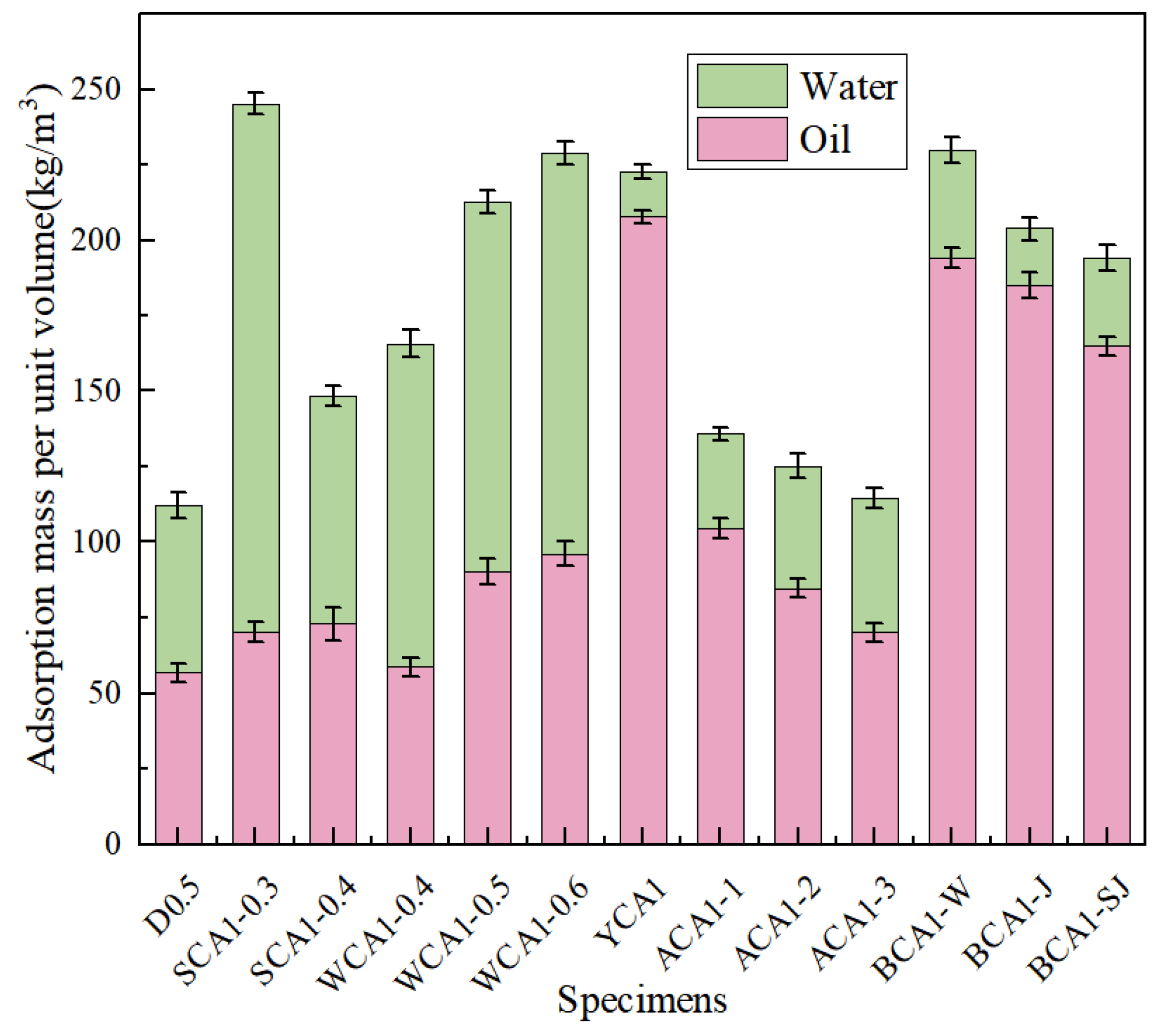
3.1. Oil Adsorption Performance

Figure 3 shows the water and oil adsorption diagram of concrete. The oil absorption performance of concrete showed a trend of initially increasing and then decreasing as the sand rates increased. When the sand rate was 35%, the oil absorption performance was at its peak. Compared with SCA1-0.3 and SCA1-0.4, it increased by 28.32% and 23.40%, respectively. In contrast, the water absorption performance showed a decreasing trend with the increase of sand rate. When the sand rate was 40%, the water absorption performance decreased by 30.05% compared to the SCA1-0.3 and by 56.93% compared to the WCA1-0.5 sample. As the water–cement ratio increased, more pores were generated, leading to an increase in oil absorption performance. Compared with the WCA1-0.4 sample, which had a water–cement ratio of 0.4, the oil absorption performance of the WCA1-0.6 sample had improved by 59.06%. At the same time, the water absorption performance exhibited a similar trend. Compared with the WCA1-0.4 sample, the water absorption performance of the WCA1-0.6 sample increased by 23.89%. This is consistent with the research of Pan et al. As the water–cement ratio increased, the water absorption performance of concrete also increased [41].
It was evident that YCA1 had the highest oil absorption capacity, which increased by 265.73% compared to D0.5. Due to the incorporation of a silane modifier, the concrete became hydrophobic, significantly reducing its water absorption performance. Compared with the D0.5 sample, the water absorption performance of the YCA1 sample was reduced by 73.06%. The results showed that the water absorption performance was improved after incorporating SC, SSC, and CSC compared to the YCA1 sample. Compared with the YCA1 sample, the water absorption performance of BCA1-W, BCA1-J, and BCA1-SJ improved by 137.86%, 26.49%, and 94.98%, respectively. This might be caused by the porous structure of the seashell powder [42].
After incorporating SC, the oil absorption capacity of BCA1-W increased by 236.57% compared to D0.5. After incorporating SSC, the oil absorption capacity of BCA1-J increased by 225.60%. After incorporating CSC, the oil absorption capacity of BCA1-SJ increased by only 172.23%. This was because CSC contains Ca(OH)2, which promoted the hydration reaction of fly ash, generated more hydration products, optimized the pore structure of concrete, and improved the adsorption performance of concrete [43]. As a result, BCA1-SJ demonstrated lower oil absorption performance compared to YCA1.
Figure 4 shows the curve of the concrete oil adsorption rate. The concrete oil absorption rate decreased as the oil absorption time increased. As shown in Figure 4a, the oil absorption rate of the WCA1-0.5 sample without hydrophobic materials decreased from 41.580 kg·m−3·d to 0.030 kg·m−3·d in 6 days.
Figure 4b shows that the YCA1 sample mixed with hydrophobic material dropped from 73.205 kg·m−3·d to 0.365 kg·m−3·d in 12 days. It showed that the saturation time of oil adsorption for concrete samples without the silane modifier was about 4 days. After adding isooctyltriethoxysilane, the oil adsorption saturation time of concrete was about 12 days, significantly extending the oil saturation time. The oil absorption rate increased significantly. The addition of the silane modifier resulted in the concrete pores becoming hydrophobic, which prevented water molecules from passing through the concrete interior. This allowed the sample to absorb more oil and extended the adsorption saturation time [44].
The pore structures of the D0.5, WCA1-0.5, YCA1, and BCA1-SJ samples were characterized by MIP. Pores are categorized into macropores (>1000 nm), capillary pores (100–1000 nm), transition pores (50–100 nm), and gel pores (<10 nm) [45]. Figure 5a,b shows the pore size distribution and pore size proportion and porosity in the concrete, respectively.
The results showed that the sample pore size distribution was mainly concentrated in the 10–100 nm range. Compared with the ordinary concrete D0.5 sample, the addition of the silane modifier caused the pore size distribution curve of the YCA1 sample to shift to the right. Compared with D0.5, the total pore volume increased by 33.89%, and the proportion of pore diameters between 10 and 100 nm increased by 11.95%. This indicated that the silane modifier caused an increase in the internal pores of the concrete. This occurred because the silane monomer produced from the hydrolysis of the hydrophobic material reacted with the hydration products of the concrete. This reaction enhanced the repulsion between the hydration products, leading to an increase in the internal pores in the concrete [46].
When CSC was incorporated, the pore size distribution curve of sample BCA1-SJ shifted to the left compared to YCA1. Additionally, the total pore volume decreased by 1.08% compared to the YCA1 sample. This might be due to the filling effect of CSC, which made the interior of the concrete denser. The pore size proportion of 10–100 nm increased by 1.92% compared to YCA1. This might be due to the fact that the addition of CSC promoted the reaction of fly ash in the concrete, leading to the production of more C-(A)-S-H gel. This process refined the pores in the concrete and increased the proportion of pores within the range of 10–100 nm.
In addition, the ROI value was defined as the ratio of the pore volume in the range of 5 nm to 100 nm to the total pore volume. The results showed that the ROI values from largest to smallest were BCA1-SJ > YCA1 > WCA1-0.5 > D0.5. The ROI values of YCA1 and BCA1-SJ were both greater than 60%, with ROI values of 61.25% and 63.16%, respectively. In summary, the ratio of pore size within the range of 10 nm to 100 nm was conducive to improving the oil absorption performance of concrete.

3.2. Compressive Strength Analysis

Figure 6a shows the strength diagram of concrete with different sand rates. As the sand rate increased from 0.3 to 0.4, the concrete strength showed an upward trend. Compared with SCA1-0.3 and SCA1-0.35, the compressive strength of the SCA1-0.4 sample at 28 days increased by 34.40%% and 21.74%, respectively. When the sand rates were low, there was an excess of cementitious material, which made bleeding more likely to occur during the concrete forming process. Numerous bleeding channels formed within the concrete, which increased the porosity of the concrete. Insufficient mortar would fail to cover the coarse aggregate surface adequately and fill the pores between the aggregates, resulting in less dense concrete. As the sand rates gradually increased, the mortar could cover the surface of the coarse aggregates and filled the pores between the aggregates, resulting in denser and stronger concrete [47].
Figure 6b shows the trend of the compressive strength of concrete as the water–cement ratio increased. The compressive strength decreased as the water–cement ratio increased. At 28 days, the compressive strength of WCA1-0.5 and WCA1-0.6 decreased by 24.35% and 45.73%, respectively, compared with WCA1-0.4. This was because the increase in the water–cement ratio resulted in an increase in the free water content in the concrete. During the curing process, the free water inside the pores evaporated, leading to an increase in the internal pores of the concrete, which ultimately reduced its strength [48].
As age increased, the strength of concrete developed rapidly at 60 days compared to at 28 days. The compressive strength of the WCA1-0.5 sample increased by 23.91% at 60 days compared to 28 days. This was because a higher abundance of water in the concrete reaction system enabled the cementitious material to react fully. This was consistent with Lam’s research results. Since the incorporation of fly ash increased the content of bound water inside the concrete, the later strength of the concrete development had sufficient water to carry out the hydration reaction [49].
Figure 7a shows the change in the compressive strength of OAC as the NaOH content increased. After adding 1% NaOH, the compressive strength of the ACA1-1 sample at 28 days increased by 4.99% compared to the YCA1 sample. This was because the addition of NaOH promoted the volcanic reaction of mineral admixtures, such as fly ash and slag, generating amorphous gels such as C-(A)-S-H, making the internal structure of concrete denser [50,51]. The compressive strength of concrete showed a downward trend as the amount of activator continued to increase. After adding 5% and 10% NaOH, the compressive strength of the ACA1-2 and ACA1-3 concrete samples at 28 days decreased by 31.38% and 46.85%, respectively, compared to YCA1 specimens. This was because as the amount of activator increased, the negatively charged monomer Si-O or Si-(OH) in the concrete would increase, increasing the repulsive force between monomers and thus delaying the condensation effect [52].
Figure 7b shows the compressive strength of concrete mixed with seashell powder in different modification methods. By incorporating SC and SSC, the compressive strength of concrete was reduced by 5.35% and 3.34%, respectively, compared to the YCA1 sample at 28 days. The main chemical composition of both SC and SSC was CaCO3, which did not significantly contribute to the hydration reaction in concrete. The incorporation of SC and SSC had been found to weaken the bond between the cementitious material and the aggregates, resulting in a decrease in concrete strength.
After incorporating CSC, the compressive strength of BCA1-SJ concrete increased by 19.62% at 28 days compared to the YCA1 sample. After acid–base modification, Ca(OH)2 was formed on the surface of the seashell powder, which promoted the reaction of fly ash to produce more C-(A)-S-H gels in concrete. CSC was rich in CO32−, which facilitated the conversion of hydrocalumite (Ca2Al(OH)6Cl·2H2O) to alumohydrocalcite (Ca4Al2(CO3)2(OH)4·6H2O) in concrete [53]. The interaction between cementitious materials, seashell powder, and aggregates strengthened the bonding effect, thereby improving the strength of the concrete.
Combining physical and chemical modification methods to modify seashell waste and incorporating it into OAC can improve its strength and maintain efficient oil absorption performance. This material can be used for river slope protection to improve slope functionality and absorb oil pollutants in the river. This can help to improve the ecological environment and promote sustainable development.

3.3. Microscopic Analysis
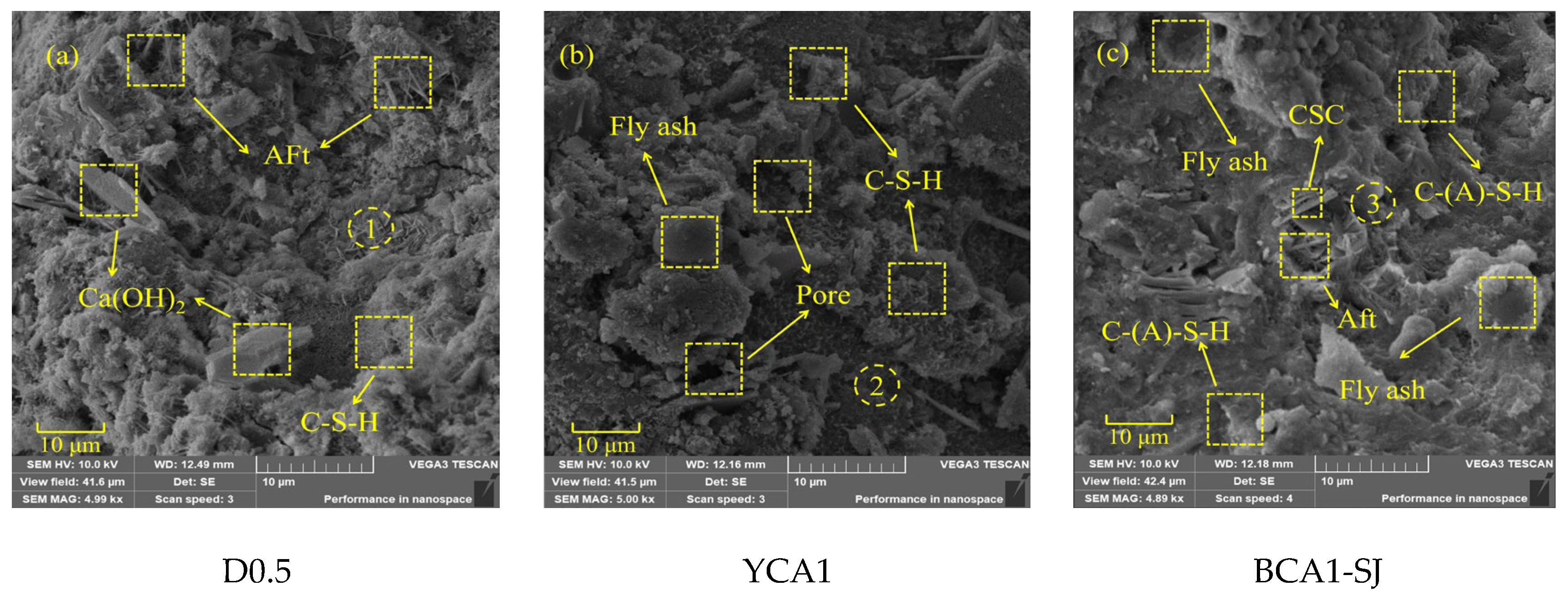
3.3.1. SEM Analysis

Scanning electron microscopy images of the D0.5, YCA1, and BCA1-SJ samples at 28 days were carried out at a magnification of 5000 times. It was found that the hydration products were wrapped around the CSC particles to form more abundant pores. Combined with EDS analysis, the results are shown in Figure 8. Compared to the YCA1, the BCA1-SJ sample exhibited fewer and smaller fly ash particles, resulting in a denser overall structure.
Figure 9 shows the EDS spectrum of the circular area in Figure 8 and the figure lists the proportion of corresponding elements. The EDS results of the D0.5 and YCA1 samples show that the calcium to silicon ratio of their hydration products is within 0.8–1.7, suggesting the amorphous gel was C-S-H in the D0.5 sample. Figure 9(2) shows that YCA1 has a higher Al content, and that Al can replace Si in the C-S-H gel to form hydrated calcium aluminosilicate (C-(A)-S-H), indicating that there is C-(A)-S-H gel present. The C-(A)-S-H gel network and ettringite generated around the CSC particles can be observed in Figure 9(3). After the addition of CSC, alumohydrocalcite is formed in the concrete. This was due to the formation of hydrocalumite during the hydration process. The incorporation of CSC increased the CO32− content in the concrete, thus replacing the Cl in the hydrocalenite to form of alumohydrocalcite [54].

3.3.2. XRD Analysis

Figure 10 shows the XRD patterns of OAC with different proportions at 28 days. The main crystal phases of OAC were Quartz and Mullite, which were obtained from fly ash in geopolymers. The diffraction peak of CaCO3 appeared at the 2θ angle of 29.42° in all samples, which was due to the absorption of CO2 from the air when the samples were exposed to the air. In addition, there was a slightly elevated dispersion peak in 2θ near 20–40°, indicating that there were amorphous and low-crystalline substances in the concrete hardening system [55]. This was because fly ash and slag would react with Ca(OH)2 to form amorphous hydration products such as C-(A)-S-H gels. These hydration products were the primary contributors to the compressive strength of concrete [56]. In addition, in the XRD patterns, the diffraction peak of AFt appeared at the 2θ angle of 9.26° in the D0.5, YCA1, and BCA1-SJ samples. Additionally, the diffraction peak of alumohydrocalcite was found in BCA1-SJ. This indicated that alumohydrocalcite was generated in BCA1-SJ.

4. Conclusions

This paper studied the compressive strength and oil absorption performance of acid–base-activated OAC. By analyzing the internal pores and components of concrete using SEM, MIP, and XRD, the following conclusions can be drawn:
(1)
By comparing the oil absorption performance and compressive strength of concrete with different sand rates and water–cement ratios, it was found that when the sand rate was 35% and the water–cement ratio was 0.5, the oil absorption performance of concrete improved by 58.69% compared to ordinary concrete. Additionally, the compressive strength reached 17.52 MPa at 28 days and 24.96 MPa at 90 days.
(2)
After adding the silane modifier, compared with ordinary concrete, the oil absorption performance improved by 265.73%. The compressive strength at 28 days was only 11.95 MPa, while at 90 days, it increased to 15.53 MPa.
(3)
By comparing the compressive strength of concrete mixed with different seashell modifications at different ages, it was found that adding CSC was beneficial for enhancing the strength of OAC. The compressive strength reached 14.32 MPa at 28 days and 17.45 MPa at 90 days, representing an increase of 19.67% and 12.36%, respectively, compared to OAC.
(4)
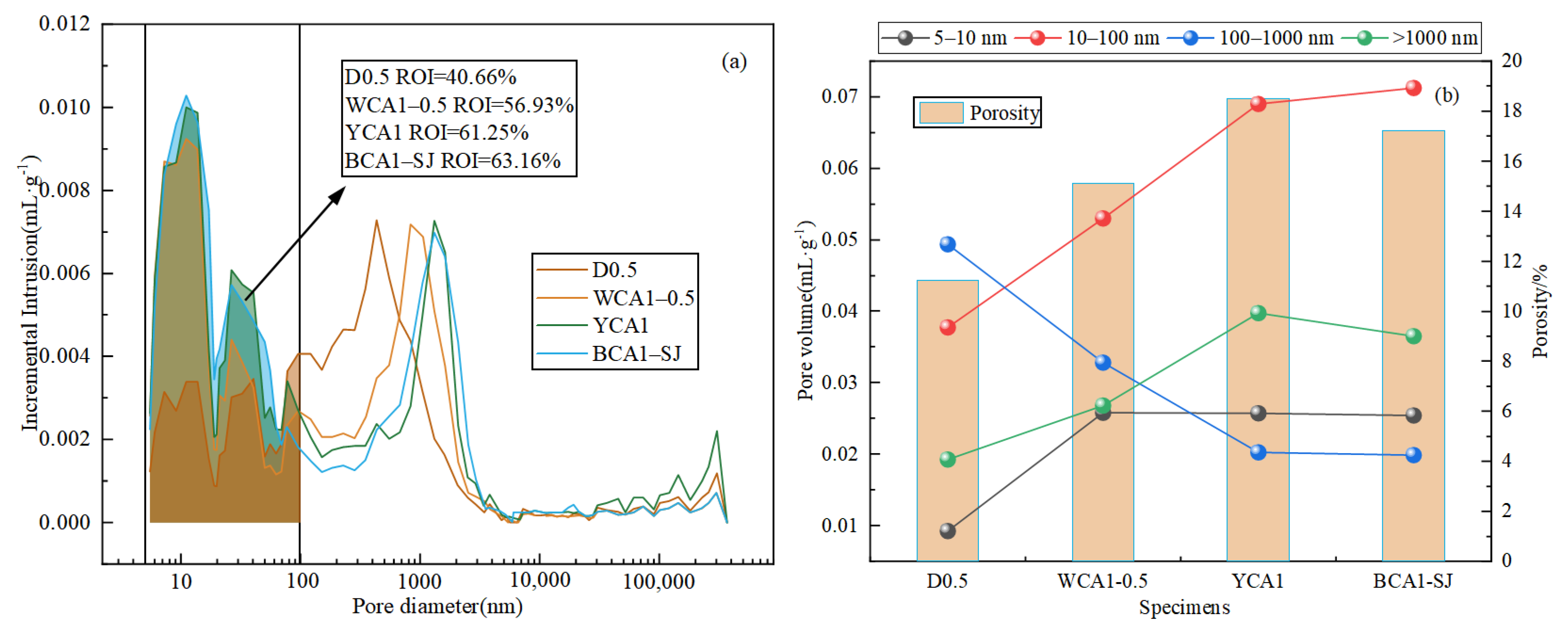
By comparing the oil absorption properties of concrete with different proportions, it was found that adding CSC increased the oil absorption performance by 172.23% compared to ordinary concrete. This might be due to the porous structure of CSC, which caused the internal pores of concrete after adding CSC to be higher than ordinary concrete. Compared to OAC, the addition of seashell powder had a negative impact on the oil absorption performance of concrete. The oil absorbent performance was in the order BCA1-W > BCA1-J > BCA1-SJ. The physical filling effect of seashell powder and the generation of Ca(OH)2 after acid–base modification in CSC might invalidate some hydrophobic material properties, thereby reducing the oil absorption properties of the concrete.
(5)
Through SEM and XRD, it was found that after adding CSC, it reacted with hydrocalumite in the concrete to produce alumohydrocalcite, as CSC was abundant in CO32−. As the calcium hydroxide content in concrete increased, the proportions of C-(A)-S-H gel and ettringite increased. The synergistic effects of the three components increased the compressive strength of OAC.
Through this study, it was found that incorporating CSC effectively improved the compressive strength of OAC while still maintaining efficient oil absorption performance. This not only helps promote the recycling of seashell waste but also absorbs a large amount of oil pollutants in the river, thus improving the ecological environment of rivers. Ultimately, the economic cost of river management can be reduced, and ecologically sustainable development can be achieved.

Author Contributions

Conceptualization, D.W.; methodology, D.W., Z.Y., H.P. and T.L.; formal analysis, D.W., Z.Y. and H.P.; investigation, D.W., Z.Y. and H.P.; resources, H.Z. and K.L.; writing—original draft preparation, D.W. and Z.Y.; writing—review and editing, D.W., Z.Y., H.Z. and H.P.; visualization, D.W., Z.Y. and H.Z.; supervision, D.W.; funding acquisition, D.W. All authors have read and agreed to the published version of the manuscript.

Funding

This study was financially supported by the Natural Science Foundation of Hebei Province (E2021107004), and the Shenzhen Science and Technology R&D fund support project (JSGG20210802152541012).

Institutional Review Board Statement

Not applicable.

Informed Consent Statement

Not applicable.

Data Availability Statement

The relevant data can be available upon request by contact with the corresponding authors.

Conflicts of Interest

The authors declare that they have no known competing financial interests or personal relationships that could have appeared to influence the work reported in this paper.

References

  1. Amari, S.; Darestani, M.; Millar, G.J.; Samali, B.; Strounina, E. Engineering and Life Cycle Assessment (LCA) of Sustainable Zeolite-Based Geopolymer Incorporating Blast Furnace Slag. Sustainability 2024, 16, 440. [Google Scholar] [CrossRef]
  2. Martinho, F.C.G.; Silva, H.M.R.D.; Oliveira, J.R.M.; Moura, C.F.N.; Loureiro, C.D.A.; Silvestre, J.D.; Rodrigues, M.M.M. Mechanical and Environmental Performance of Asphalt Concrete with High Amounts of Recycled Concrete Aggregates (RCA) for Use in Surface Courses of Pavements. Sustainability 2023, 16, 248. [Google Scholar] [CrossRef]
  3. Kaptan, K.; Cunha, S.; Aguiar, J. A Review: Construction and Demolition Waste as a Novel Source for CO2 Reduction in Portland Cement Production for Concrete. Sustainability 2024, 16, 585. [Google Scholar] [CrossRef]
  4. Silva, A.; Nogueira, R.; Bogas, J.A. Strategies for OPC Paste Carbonation: Relationship between Microstructure, Performance and Net CO2 Balance. Sustainability 2023, 16, 361. [Google Scholar] [CrossRef]
  5. Chen, X.F.; Jiao, C.J. A photocatalytic mortar prepared by tourmaline and TiO2 treated recycled aggregates and its air-purifying performance. Case Stud. Constr. Mat. 2022, 16, e01073. [Google Scholar] [CrossRef]
  6. Chen, X.F.; Jiao, C.J. Effect of construction wastes on the rheo-physical behavior of photocatalytic mortar. Case Stud. Constr. Mat. 2022, 16, e01049. [Google Scholar] [CrossRef]
  7. Carpenter, A. Oil pollution in the North Sea: The impact of governance measures on oil pollution over several decades. Hydrobiologia 2019, 845, 109–127. [Google Scholar] [CrossRef]
  8. Zhang, B.; Matchinski, E.J.; Chen, B.; Ye, X.; Jing, L.; Lee, K. Marine Oil Spills—Oil Pollution, Sources and Effects, World Seas: An Environmental Evaluation; Academic Press: Cambridge, MA, USA, 2019; pp. 391–406. [Google Scholar] [CrossRef]
  9. Wang, D.; Liu, S.; Dong, B.; Yuan, L.; Pan, H.; Zhao, Q. Research Progress on Factors Affecting Oil-Absorption Performance of Cement-Based Materials. Materials 2023, 16, 3166. [Google Scholar] [CrossRef]
  10. Mora, E.; González, G.; Romero, P.; Castellón, E. Control of water absorption in concrete materials by modification with hybrid hydrophobic silica particles. Constr. Build. Mater. 2019, 221, 210–218. [Google Scholar] [CrossRef]
  11. Liu, B.; Shi, J.; Sun, M.; He, Z.; Xu, H.; Tan, J. Mechanical and permeability properties of polymer-modified concrete using hydrophobic agent. J. Build. Eng. 2020, 31, 101337. [Google Scholar] [CrossRef]
  12. Wang, Z.; Ma, H.Y.; Chu, B.; Hsiao, B.S. Super-hydrophobic modification of porous natural polymer “luffa sponge” for oil absorption. Polymer 2017, 126, 470–476. [Google Scholar] [CrossRef]
  13. Hou, D.; Zhao, T.; Wang, P.; Li, Z.; Zhang, J. Molecular dynamics study on the mode I fracture of calcium silicate hydrate under tensile loading. Eng. Fract. Mech. 2014, 131, 557–569. [Google Scholar] [CrossRef]
  14. Hou, D.; Lu, C.; Zhao, T.; Zhang, P.; Ding, Q. Structural, dynamic and mechanical evolution of water confined in the nanopores of disordered calcium silicate sheets. Microfluid. Nanofluid. 2015, 19, 1309–1323. [Google Scholar] [CrossRef]
  15. Li, Q.; Yang, K.; Yang, C.H. An alternative admixture to reduce sorptivity of alkali-activated slag cement by optimising pore structure and introducing hydrophobic film. Cem. Concr. Compos. 2019, 95, 183–192. [Google Scholar] [CrossRef]
  16. He, B.; Gao, Y.; Qu, L.; Duan, K.; Zhou, W.; Pei, G. Characteristics analysis of self-luminescent cement-based composite materials with self-cleaning effect. J. Clean. Prod. 2019, 225, 1169–1183. [Google Scholar] [CrossRef]
  17. Hou, P.; Li, R.; Li, H.; Xie, N.; Cheng, X.; Singh, L.P. The use of hydrophobicity and pozzolanic reactivity of the PMHS/nanosilica hybrid composites on the water absorption of cement mortar. J. Therm. Anal. Calorim. 2018, 134, 1775–1784. [Google Scholar] [CrossRef]
  18. Zhao, J.; Gao, X.; Chen, S.; Lin, H.; Li, Z.; Lin, X. Hydrophobic or superhydrophobic modification of cement-based materials: A systematic review. Compos. Part B Eng. 2022, 243, 110104. [Google Scholar] [CrossRef]
  19. Feng, Z.; Wang, F.; Xie, T.; Ou, J.; Xue, M.; Li, W. Integral hydrophobic concrete without using silane. Constr. Build. Mater. 2019, 227, 116678. [Google Scholar] [CrossRef]
  20. Aubert, J.E.; Husson, B.; Vaquier, A. Use of municipal solid waste incineration fly ash in concrete. Cem. Concr. Res. 2004, 34, 957–963. [Google Scholar] [CrossRef]
  21. Hemalatha, T.; Ramaswamy, A. A review on fly ash characteristics–Towards promoting high volume utilization in developing sustainable concrete. J. Clean. Prod. 2017, 147, 546–559. [Google Scholar] [CrossRef]
  22. Wang, J.J.; Liu, E.G.; Li, L. Characterization on the recycling of waste seashells with Portland cement towards sustainable cementitious materials. J. Clean. Prod. 2019, 220, 235–252. [Google Scholar] [CrossRef]
  23. Djobo, Y.J.N.; Elimbi, A.; Dika Manga, J.; Djon Li Ndjock, I.B. Partial replacement of volcanic ash by bauxite and calcined oyster shell in the synthesis of volcanic ash-based geopolymers. Constr. Build. Mater. 2016, 113, 673–681. [Google Scholar] [CrossRef]
  24. Kuo, W.T.; Wang, H.Y.; Shu, C.Y.; Su, D.S. Engineering properties of controlled low-strength materials containing waste oyster shells. Constr. Build. Mater. 2013, 46, 128–133. [Google Scholar] [CrossRef]
  25. Tayeh, B.A.; Hasaniyah, M.W.; Zeyad, A.M.; Awad, M.M.; Alaskar, A.; Mohamed, A.M.; Alyousef, R. Durability and mechanical properties of seashell partially-replaced cement. J. Build. Eng. 2020, 31, 101328. [Google Scholar] [CrossRef]
  26. Tayeh, B.A.; Hasaniyah, M.W.; Zeyad, A.; Yusuf, M.O. Properties of concrete containing recycled seashells as cement partial replacement: A review. J. Clean. Prod. 2019, 237, 117723. [Google Scholar] [CrossRef]
  27. Olivia, M.; Oktaviani, R. Properties of concrete containing ground waste cockle and clam seashells. Procedia Eng. 2017, 171, 658–663. [Google Scholar] [CrossRef]
  28. Ruengsillapanun, K.; Udtaranakron, T.; Pulngern, T.; Tangchirapat, W.; Jaturapitakkul, C. Mechanical properties, shrinkage, and heat evolution of alkali activated fly ash concrete. Constr. Build. Mater. 2021, 299, 123954. [Google Scholar] [CrossRef]
  29. Chi, M.; Huang, R. Binding mechanism and properties of alkali-activated fly ash/slag mortars. Constr. Build. Mater. 2013, 40, 291–298. [Google Scholar]
  30. Oderji, S.Y.; Chen, B.; Ahmad, M.R.; Shah, S.F.A. Fresh and hardened properties of one-part fly ash-based geopolymer binders cured at room temperature: Effect of slag and alkali activators. J. Clean. Prod. 2019, 225, 1–10. [Google Scholar] [CrossRef]
  31. Wardhono, A. The effect of seashell waste on setting and strength properties of class c fly ash geopolymer concrete cured at ambient temperature. J. Eng. Sci. Technol. 2019, 14, 1220–1230. [Google Scholar]
  32. Hasnaoui, A.; Bourguiba, A.; El Mendili, Y.; Sebaibi, N.; Boutouil, M. A preliminary investigation of a novel mortar based on alkali-activated seashell waste powder. Powder Technol. 2021, 389, 471–481. [Google Scholar] [CrossRef]
  33. Yun, Y.J.; Lee, S.; Kim, Y.; Ryu, Y.B. Effect of Various Acid Solutions on the CO2 Dissolution Rate, Morphology, and Particle Size of Precipitated Calcium Carbonate Synthesized Using Seashells. Materials 2023, 16, 7665. [Google Scholar] [CrossRef]
  34. Upadhayay, P.; Pal, P.; Zhang, D.; Pal, A. Sea Shell Extracted Chitosan Composites and Their Applications. Compos. Aquat. Environ. 2023, 2023, 293–314. [Google Scholar] [CrossRef]
  35. Wang, T.; Yang, L.; Rao, F.; Jiang, K.; Byrynnai, C. Effect of chitosan on the mechanical properties and acid resistance of metakaolin-blast furnance slag–based geopolymers. Environ. Sci. Pollut. Res. 2023, 30, 47025–47037. [Google Scholar] [CrossRef]
  36. Li, Z.; Chen, R.; Zhang, L.Y. Utilization of chitosan biopolymer to enhance fly ash-based geopolymer. J. Mater. Sci. 2013, 48, 7986–7993. [Google Scholar] [CrossRef]
  37. Wang, D.; Liu, S.; Yuan, L.; Dong, B.; Wu, D.; Zhao, Q. 1H NMR monitoring of dynamic microstructure evolution of HACP during adsorption of different fluids. Constr. Build. Mater. 2024, 411, 134462. [Google Scholar] [CrossRef]
  38. Wang, D.; Wu, X.; Yuan, L.; Wu, D.; Zhao, Q.; Pan, H.; Qi, W. Oil absorption and plant symbiosis capacity of hydrophobic modified concrete: Preparation and performance analysis. Constr. Build. Mater. 2024, 413, 134897. [Google Scholar] [CrossRef]
  39. Alabaraoye, E.; Achilonu, M.; Hester, R. Biopolymer (Chitin) from various marine seashell wastes: Isolation and characterization. J. Polym. Environ. 2018, 26, 2207–2218. [Google Scholar] [CrossRef]
  40. GB/T 50081-2019; Standard for Test Methods of Concrete Physical and Mechanical Properties. Chinese Standard: Beijing, China, 2019.
  41. Pan, D.; Chen, K.; Niu, D.; Leung, C.K.Y.; Li, Z. Capillary water absorption and free shrinkage characterization for seawater sea-sand concrete. J. Build. Eng. 2024, 87, 109119. [Google Scholar] [CrossRef]
  42. Eziefula, U.G.; Ezeh, J.C.; Eziefula, B.I. Properties of seashell aggregate concrete: A review. Constr. Build. Mater. 2018, 192, 287–300. [Google Scholar] [CrossRef]
  43. Temuujin, J.; Van Riessen, A.; Williams, R. Williams. Influence of calcium compounds on the mechanical properties of fly ash geopolymer pastes. J. Hazard. Mater. 2009, 167, 82–88. [Google Scholar] [CrossRef]
  44. Liu, B.J.; Luo, G.; Xie, Y.J. Effect of curing conditions on the permeability of concrete with high volume mineral admixtures. Constr. Build. Mater. 2018, 167, 359–371. [Google Scholar] [CrossRef]
  45. Zhang, J.; Bian, F.; Zhang, Y.; Fang, Z.; Fu, C.; Guo, J. Effect of pore structures on gas permeability and chloride diffusivity of concrete. Constr. Build. Mater. 2018, 163, 402–413. [Google Scholar] [CrossRef]
  46. Zhang, B.; Li, Q.; Ma, R.; Niu, X.; Yang, L.; Hu, Y.; Zhang, J. The influence of a novel hydrophobic agent on the internal defect and multi-scale pore structure of concrete. Materials 2021, 14, 609. [Google Scholar] [CrossRef]
  47. Prabhu, G.G.; Hyun, J.H.; Kim, Y.Y. Effects of foundry sand as a fine aggregate in concrete production. Constr. Build. Mater. 2014, 70, 514–521. [Google Scholar] [CrossRef]
  48. Liu, J.; Ge, T.; Wu, Y.; Chen, R. Effect of Sand-to-Cement Ratio on Mechanical Properties of Foam Concrete. Buildings 2022, 12, 1969. [Google Scholar] [CrossRef]
  49. Lam, L.; Wong, Y.L.; Poon, C.S. Degree of hydration and gel/space ratio of high-volume fly ash/cement systems. Cem. Concr. Res. 2000, 30, 747–756. [Google Scholar] [CrossRef]
  50. Rattanasak, U.; Chindaprasirt, P. Influence of NaOH solution on the synthesis of fly ash geopolymer. Miner. Eng. 2009, 22, 1073–1078. [Google Scholar] [CrossRef]
  51. Görhan, G.; Kürklü, G. The influence of the NaOH solution on the properties of the fly ash-based geopolymer mortar cured at different temperatures. Compos. Part B Eng. 2014, 58, 371–377. [Google Scholar] [CrossRef]
  52. Rifaai, Y.; Yahia, A.; Mostafa, A.; Aggoun, S.; Kadri, E.-H. Rheology of fly ash-based geopolymer: Effect of NaOH concentration. Constr. Build. Mater. 2019, 223, 583–594. [Google Scholar] [CrossRef]
  53. Ipavec, A.; Gabrovšek, R.; Vuk, T.; Kaučič, V.; Maček, J.; Meden, A. Carboaluminate phases formation during the hydration of calcite-containing Portland cement. J. Am. Ceram. Soc. 2011, 94, 1238–1242. [Google Scholar] [CrossRef]
  54. Ramachandran, V.S.; Zhang, C.M. Thermal analysis of the 3CaO· Al2O3-CaSO4· 2H2O-CaCO3-H2O system. Thermochim. Acta 1986, 106, 273–282. [Google Scholar] [CrossRef]
  55. Gu, X.; Tan, H.; He, X.; Zhang, J.; Li, M.; Su, Y.; Yang, J. Nano CSH seeds prepared from ground granulated blast-furnace slag-carbide slag and its application in Portland cement. Constr. Build. Mater. 2022, 329, 127204. [Google Scholar] [CrossRef]
  56. Da, Y.; Laixue, P.; Di, S.; Mingyang, L.U.; Jiabin, W.; Zebin, G. Reaction mechanism of fly ash in alkali-activated slag/fly ash system. Bull. Chin. Ceram. Soc. 2021, 40, 3005–3011. [Google Scholar] [CrossRef]
Figure 1. Seashell particle size analysis and XRD: (a) seashell particle size analysis; (b) seashell XRD before and after modification.
Sustainability 16 03661 g001
Figure 2. Sample preparation and test flow chart.
Sustainability 16 03661 g002
Figure 3. Water and oil adsorption of concrete samples.
Sustainability 16 03661 g003
Figure 4. Oil absorption rate curves of concrete samples: (a) no hydrophobic materials added; (b) hydrophobic materials added.
Sustainability 16 03661 g004
Figure 5. Pore size distribution diagram of OAC: (a) pore size distribution; (b) pore size proportion and porosity.
Sustainability 16 03661 g005
Figure 6. Compressive strength of concrete: (a) different sand rates; (b) different water–cement ratio.
Sustainability 16 03661 g006
Figure 7. Compressive strength of concrete: (a) different NaOH contents; (b) different modifications of seashell.
Sustainability 16 03661 g007
Figure 8. SEM images of concrete samples: (a) D0.5; (b) YCA1; (c) BCA1-SJ.
Sustainability 16 03661 g008
Figure 9. EDS images of concrete samples: (1) D0.5; (2) YCA1; (3) BCA1-SJ.
Sustainability 16 03661 g009
Figure 10. XRD pattern of concrete.
Sustainability 16 03661 g010
Table 1. The main chemical compositions of cementitious materials.
MaterialsCaO/%SiO2/%Al2O3/%Fe2O3/%MgO/%K2O/%SO3/%Others/%
Cement63.4020.604.793.142.621.053.680.72
Fly ash4.4842.744.80.381.140.615.89
S95 Slag32.3032.9017.408.390.612.815.59
Table 2. Main physical properties of fine and coarse aggregates.
MaterialsApparent Density (kg/m3)Bulk Density (kg/m3)Absorption (%)Crush Value (%)
Manufactured Sand2630 ± 31740 ± 2
Gravel2730 ± 21510 ± 42.5 ± 0.311.8 ± 0.2
Table 3. Concrete mix ratio.
NumberCementFly
Ash
S95 SlagNaOHSeashellSilane ModifierSandStoneWaterRemarks
D0.511.202.230.5
SCA1-0.313.460.485.0911.872.47
SCA1-0.413.460.486.7710.192.47
WCA1-0.413.460.485.9411.021.98
WCA1-0.513.460.485.9411.022.47
WCA1-0.613.460.485.9411.022.96
YCA113.460.485.9411.022.47
ACA1-113.460.480.050.155.9411.022.47
ACA1-213.460.480.250.155.9411.022.47
ACA1-313.460.480.500.155.9411.022.47
BCA1-W13.460.480.490.155.9411.022.47Unprocessed
BCA1-J13.460.480.490.155.9411.022.47Alkali-modified
BCA1-SJ13.460.480.490.155.9411.022.47Acid–base-modified
Disclaimer/Publisher’s Note: The statements, opinions and data contained in all publications are solely those of the individual author(s) and contributor(s) and not of MDPI and/or the editor(s). MDPI and/or the editor(s) disclaim responsibility for any injury to people or property resulting from any ideas, methods, instructions or products referred to in the content.

