Heat-Transfer Characteristics of a Cryogenic Loop Heat Pipe for Space Applications


Department of Mechanical Engineering, Changwon National University, 20 Changwondaehak-ro, Uichang-gu, Changwon-si, Gyeongsangnam-do 51140, Korea
*
Author to whom correspondence should be addressed.
Energies 2020, 13(7), 1616; https://0-doi-org.brum.beds.ac.uk/10.3390/en13071616
Submission received: 11 March 2020
/
Revised: 26 March 2020
/
Accepted: 29 March 2020
/
Published: 2 April 2020
(This article belongs to the Collection Advances in Heat Transfer Enhancement)
Abstract
:Infrared detectors on satellites and spacecraft require cooling to increase their measurement sensitivity. To efficiently cool infrared detectors in a zero gravity environment and in limited spaces, a cryogenic loop heat pipe (CLHP) can be used to transfer heat over a certain distance by the capillary forces generated from porous wicks without a mechanical power source. The CLHP presented in this study transfers the heat load to a condenser 0.5 m away from an evaporator at temperatures below −150 °C. The CLHP with two evaporators includes a subloop for initial start-up, and uses a pressure reduction reservoir (PRR) for the supercritical start-up from room to cryogenic temperature. Nitrogen is used as the working fluid to verify the thermal behavior of the CLHP, and the heat-transfer capacity according to the nitrogen charging pressure of the PRR is investigated. To simulate a cryogenic environment, the CLHP is installed inside a space environment simulator, including a single-stage GM (Gifford McMahon) cryocooler to cool the condenser. The CLHP is horizontally installed to simulate zero gravity. The heat-transfer characteristics are experimentally evaluated through the loop circulation of the CLHP.
1. Introduction
Infrared detectors for space applications require efficient cooling to increase their measurement sensitivity. A cooling system is needed to cool infrared detectors over a certain distance in zero gravity and limited spaces. Heat pipes are devices that transfer heat from high- to low-temperature parts based on the phase change; they can effectively cool infrared detectors [1,2,3,4,5]. Heat pipes have evolved in various forms since the early the 1960s; they are simple in structure and can be applied to various fields over a wide temperature range [1,2,3,4,5,6,7]. Heat pipes involve phase changes of working fluids to minimize temperature differences. In the case of a thermosiphon, evaporated vapor and condensed liquid can be transported by buoyance forces subjected to gravity, which is similar to natural convection [8,9]. However, the main transportation mechanism of the heat pipes is capillary pressure generated in the wick structure of the evaporator; this can be used in zero gravity, e.g., in a space environment [10,11,12,13,14]. A simple heat pipe has the drawback of low heat-transfer efficiency because the vapor and liquid are in the same space. The use of loop heat pipes with separate vapor and liquid piping can compensate for this drawback.
In 1998, a cryogenic loop heat pipe (CLHP) was developed in Japan using nitrogen, neon, hydrogen, and helium as the working fluids [15]. Since 2000, various studies on the CLHP have been conducted. Zhao et al. designed and experimentally investigated a CLHP to cool parallel condensers using liquid nitrogen, and showed a maximum heat-transfer capacity of 41 W at a heat-transfer distance of 0.48 m, a shroud temperature of 170 K, and a limited temperature difference of 6 K [16]. Gully et al. experimentally investigated a prototype CLHP operating at 80 K using liquid nitrogen and achieved a maximum heat-transfer capacity of 19 W, a temperature difference of 5 K, and a heat-transfer distance of 0.5 m [17]. Bai et al. designed a compact CLHP consisting of a primary and secondary evaporator using nitrogen as a working fluid, and studied supercritical start-up with a secondary evaporator. The maximum heat transport capability was shown to be 5 W with a transport distance of 4.3 m [18,19]. Yan et al. verified theoretical evaluations and experiments on the working fluid inventory inside the CLHP [20]. Guo et al. improved the reliability of the CLHP, and performed supercritical start-up experiments in both independent and dual operation modes for two evaporators [21]. The CLHP has been proven in various previous studies to be an effective heat-transfer device in cryogenic environments [16,17,18,19,20,21,22].
Previous studies have clearly demonstrated the heat-transfer performance of CLHPs, but some aspects have not been properly considered, e.g., a thermo-hydraulic design for loop circulation, optimization of the cooling flow path in the condenser, the thermal behavior of the CLHP in a subcooled condenser, and the durability of the CLHP for long-term operation.
In this study, a CLHP for use in space was designed and fabricated, and its performance was evaluated by simulating cryogenic and zero gravity environments. The thermo-hydraulic design minimizes the pressure drop of the CLHP and optimizes the length of the condenser cooling flow path through a 1D-node network analysis. The thermal behavior was investigated while the condenser temperature was set at 75 K using a temperature controller and a single-stage Gifford McMahon (GM) cryocooler. The heat-transfer characteristics of the CLHP according to the heat load applied to the main evaporator are represented by temperature difference and thermal resistance, which shows the heat-transfer performance of the CLHP. To evaluate the heat-transfer characteristics, we simulated a cryogenic environment using the single-stage GM cryocooler. Additionally, the CLHP employs a pressure reduction reservoir (PRR) for supercritical start-up from room to cryogenic temperature, and the working fluid is nitrogen. The single-stage GM cryocooler was set to 75 K to keep the condenser at a constant temperature, making it subcooled at all times. The heat-transfer performance of the CLHP was verified for a heat-transfer distance of 500 mm at temperatures below −150 °C. Long-term experiments were also conducted over 32 hours to verify operational stability.
2. Design and Fabrication of the CLHP
2.1. Configuration and Operation of the CLHP
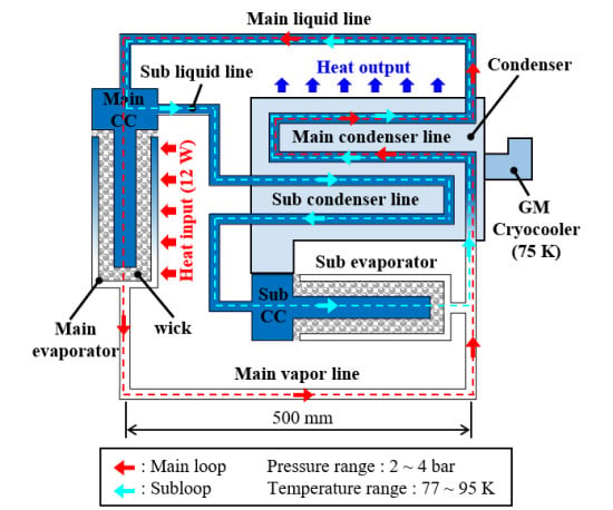
The CLHP consists of a condenser, an evaporator, and a vapor/liquid line. The condenser is attached to the single-stage GM cryocooler to condense the working fluid inside it by conduction cooling. The CLHP has two evaporators, i.e., the main and sub. The evaporator consists of a wick and a compensation chamber (CC), which is a device that makes it possible for the working fluid to circulate through the loop with capillary pressure. The vapor/liquid line is the path through which the working fluid flows between the evaporator and condenser, and corresponds to the pipe connecting the evaporator and condenser. Figure 1 shows a schematic of the CLHP.
The initial state of the CLHP is divided into liquid and gaseous states, and the working fluid is condensed around the condenser connected to the single-stage GM cryocooler. When a heat load is applied to the subevaporator to circulate through the subloop, the liquid nitrogen (LN2) is vaporized in the subevaporator and flows through the vapor line to the condenser. At this time, the wick inside the evaporator absorbs LN2 by capillary force, the vaporized gaseous nitrogen (GN2) flows into the condenser, and the liquid in the condenser flows through the main liquid line to the main CC. At the start of the subloop circulation, cold GN2 enters the main CC, part of it passes through the subliquid line and condenser, and then returns through to the subevaporator and sub-CC. When the LN2 of the main CC is sufficiently filled, the heat load of the subevaporator is removed and the heat load of the main evaporator is applied to the main evaporator to circulate the main loop.
2.2. Design of the CLHP
2.2.1. Design of the Wick
The wick evaporates the LN2 by capillary force and heat to generate a differential pressure and circulate the loop of CLHP [10,11,12,13,14]. Capillary pressures that can occur at the interface of the working fluid are calculated using the following equation [13]:
where is capillary pressure, is surface tension of working fluid, is contact angle, and is pore radius. Since the contact angle is not exactly known for our configuration, the maximum possible capillary pressure is less than that from Equation (1). Table 1 presents the results of the calculated maximum capillary pressure in the wick when LN2 is used as the working fluid for given pressures.
2.2.2. Design of the Evaporator
The internal structure of the evaporator is divided into a wick and a CC. The working fluid liquefied in the condenser enters the CC inside the evaporator, which is filled with liquid. The working fluid is absorbed into the wick by capillary force. The working fluid inside the wick is evaporated and discharged into the vapor line by the heat load, and the liquid filled in the CC is absorbed into the wick. Figure 2 shows the structure of the evaporator, and Table 2 lists the design specifications of the evaporators.
2.2.3. Design of the Condenser
The working fluid inside the CLHP is liquefied in a condenser connected to a single-stage GM cryocooler. The condenser uses copper, a material with good thermal conductivity, for sufficient liquefaction inside it. The saturation temperature of the working fluid changes depending on the pressure conditions inside the CLHP, and thus, the temperature in the condenser must be controlled taking into account the internal pressure. The following conditions should be considered for the condenser design: the length of the cooling flow path for the working fluid to be sufficiently liquefied, and the pressure drop according to the flow path shape.
The 5 parallel pipes were applied to reduce the pressure drop inside the condenser, and a 1D-node network analysis was performed to calculate the cooling channel length. The 1D node network analysis programs used SINDA/FLUINT(Sinap®), and two phase flows were analyzed using McAdam’s Homogeneous model to optimize cooling flow paths [23]. The 1D-node network analysis was performed according to the pressure conditions, heat loads, and the length of the flow paths in which the working fluids could be sufficiently liquefied inside the condenser. Table 3 presents the conditions of the 1D-node network simulation analysis for calculating the cooling flow path length. Figure 3 shows the working fluid temperature and void fraction along the condenser cooling flow path. GN2 entering the condenser is liquefied after 60, 80 and 100 mm from the condenser inlet at a working pressure of 2, 3 and 4 bar, respectively. Based on the results of the simulation, the length of the cooling flow path was determined to be 150 mm for sufficient liquefaction of the working fluid to occur in the condenser.
2.2.4. Pressure Drop in the CLHP
The pressure drop is caused by the shape of the flow path and friction when the working fluid flows inside the flow path; this affects the efficiency of the CLHP. The pressure drop generated inside the CLHP was calculated by dividing it into the evaporator, condenser, and vapor/liquid line. The pressure drop inside the evaporator occurs mostly in the wick. The pressure drop that occurs when liquid enters the wick is calculated using the following equation [24]:
where is the permeability of the wick, is the pore radius of the wick, is the porosity of the wick, is a friction factor of liquid flow, is the viscosity of the liquid, is the sectional area of the wick, is the latent heat of vaporization, is the density of the liquid, is the pressure drop of the wick, is the heat load applied to the evaporator, and is the length of liquid flow. Table 4 presents the pressure drop of the wick due to liquid flow in the evaporator.
The pressure drop in the flow path inside the CLHP is calculated using the Darcy-Weisbach equation:
where is pressure drop, is the friction factor, is length, is the hydraulic diameter, is density, is velocity, and is the minor loss coefficient. To calculate the pressure drop in the condenser, it was assumed that half of the condenser is filled by gas and the rest with liquid based on the simulation results. To construct the vapor/liquid line connecting the condenser and evaporator of the CLHP, it was necessary to consider the pressure drop in the pipe. Table 5 lists the necessary conditions for calculating the pressure drop in the vapor/liquid line.
To circulate the loop of the CLHP, the maximum generated differential pressure in the wick must be greater than the total pressure drop inside the CLHP. Table 6 presents the total pressure drop in the CLHP. When comparing the maximum generated differential pressure by the wick with the total pressure drop of the CLHP, it was determined that the pressure drop in the circulation of the CLHP loop was sufficiently compensated for because the generated differential pressure of the wick (5731.4 Pa at 1 bar) was greater than the CLHP total pressure drop (1876.3 Pa at 1 bar).
2.3. Fabrication of the CLHP
The evaporator was fabricated using the shrinkage fitting method. This method uses the tolerances due to the thermal shrinkage and expansion of the material caused by the difference in temperature. The evaporator housing was heated to more than 350 °C, and the wick was cooled with LN2. The fabricated evaporator brazed the vapor/liquid piping. The condenser is fabricated by soldering a upper plate and a bottom plate having the cooling flow paths. The CLHP was completed by assembling the evaporators, the vapor/liquid piping, and the condenser. Figure 4 shows the fabrication process of the CLHP.
3. Heat-Transfer Characteristic Experiment of the CLHP
3.1. Experimental Setup
To investigate the thermal behavior of the CLHP, a temperature sensor (PT-100) was installed at a location where the temperature changes could be observed. Figure 5 shows the temperature sensor installed in the CLHP.
The experimental setup consisted of a space environment simulator, a single-stage GM cryocooler, a compressor, a vacuum pump, and measuring equipment. The space environment simulator is a device for simulating a cryogenic environment and zero gravity. The vacuum pump, the single-stage GM cryocooler, and the compressor were used to keep the interior of the space simulator at cryogenic temperature. The data measurement devices included a vacuum gauge, a vacuum controller, a temperature monitor, a temperature controller, a SCXI, and a mass flow meter. The CLHP was installed horizontally inside the space environment simulator to simulate zero gravity. A PRR was installed for supercritical start-up from room to cryogenic temperature. Figure 6 shows the experimental setup, and Table 7 lists the experimental conditions for determining the heat-transfer characteristics of the CLHP.
3.2. Supercritical Start-up and Subloop Circulation of the CLHP
The PRR, charged with 53.5 g (14 bar) of nitrogen, was connected to the CLHP to inject nitrogen for the supercritical start-up of the CLHP. The CLHP was cooled using the single-stage GM cryocooler, and 14 h after the start of cooling, LN2 entered the main CC. The subloop was circulated by applying a heat load to the subevaporator. Figure 7 shows the supercritical start-up of the CLHP and temperature change over time, from room to cryogenic temperature. The GN2 inside the CLHP was slowly cooled by the condenser connected to the single-stage GM cryocooler, and after 14 h, the temperature dropped sharply in the vapor zone containing the main evaporator. The reason for this phenomenon is that LN2 is supplied to the main CC so that the temperature of the main evaporator and CC reaches the saturation value inside the system.
Figure 8 shows the change in the CLHP internal temperature and pressure when the subloop was circulated with a heat load of 1 W after the main CC was sufficiently filled with LN2. In the process of filling the main CC with LN2, the pressure change tended to be similar to the temperature change in the main CC. The pressure inside the CLHP was maintained at approximately 1.8 bar with a saturation temperature of 82.5 K. The temperature of the main evaporator and main CC was maintained at 82.5 K, and there was a slight change, which appeared to occur during internal equilibrium with the GN2 supplied from the PRR and LN2 liquefied from the condenser. After cooling to saturation temperature according to the pressure inside the CLHP, when the subevaporator was heated to circulate the subloop, the temperature changed as the vapor and liquid flowed inside the main liquid line and the subliquid line of the CLHP. As the subloop was circulated, the main CC was filled with LN2; the temperature of the subliquid line was approximately 84 K and the temperature difference was less than 1 K. After a certain time, the temperature of the subliquid line dropped to 83.5 K and the temperature difference was less than 0.5 K. At this point, it was determined that the main CC was sufficiently filled with LN2.
3.3. Main Loop Circulation of the CLHP
After the main CC was sufficiently filled with LN2 in the subloop circulation, the CLHP internal pressure was maintained at 2.2 bar, and the temperature of the main evaporator and main CC converged at the saturation temperature of the CLHP internal pressure. Figure 9 shows the temperature and pressure changes when a heat load of 1 W was applied to the main evaporator after CLHP temperature convergence. Before applying the heat load to the main evaporator, the temperature converged at a temperature corresponding to the pressure inside the CLHP, and the main liquid line was in a slug flow where the working fluid mixes vapor and liquid. At a heat load of 1 W, the temperature of the main evaporator and main CC increased, raising the internal pressure. The working fluid vaporized in the wick inside the main evaporator and was discharged into the main vapor line. Due to the capillary force of the wick, the condensed LN2 entered the evaporator via the main CC.
When the main CC was sufficiently filled with LN2, the heat load of the subevaporator was removed. The heat load was then applied to the main evaporator to circulate the main loop. To investigate the internal thermal behavior of the CLHP, an initial heat load of 1 W was applied and increased by 1 W at 1-h intervals.
Figure 10 shows the change in temperature over time as the heat load was applied to the main evaporator to circulate in the main loop. When the main CC was sufficiently filled with liquid, the temperature of the main CC and the main evaporator converged at 84.5 K, and when a heat load of 1 W was applied to the main evaporator, the temperature converged at 87.35 K. The temperature of the main evaporator converged at 88.64, 89.05, 89.44, 90.92, 91.26, 91.42, 91.7, and 92.97 K when the heat load was increased by 1 W over eight 1-h intervals. With a heat load of 10 W, the temperature of the main evaporator and main CC increased sharply, and dry-out occurred.
Figure 11 shows the temperature change in the CLHP when dry-out occurred. The temperature of the main evaporator and main steam line rose quickly, causing the pressure inside the CLHP to increase rapidly. The temperature of the vapor/liquid line, except for the main vapor line, was maintained at 78–79 K, similar that of to the condenser, and LN2 was supplied to the main CC via the main liquid line. The temperature of the main CC increased more slowly than that of the main evaporator, but after approximately 10 min, the temperature increased quickly. The reason for the rapid change in temperature of the main evaporator and main CC seems to be that not enough LN2 was supplied to the main CC.
To investigate the heat-transfer properties of the CLHP, additional experiments were performed by filling 50(13.1), 55(14.4), and 60(15.7) g(bar) of nitrogen in the PRR. When the main CC was sufficiently filled with LN2, the heat load of the subevaporator was removed. The heat load was then applied to the main evaporator to circulate the main loop. The initial heat load was applied at 1 W and increased by 1 W at 30-min intervals. The temperature and pressure inside the CLHP converged at saturation. When the PRR was charged with 50 g (13.1 bar) of nitrogen, the maximum heat transfer reached 8 W and dry-out at a heat load of 9 W. At 55 g (14.4 bar) of nitrogen, the maximum heat transfer achieved 12 W and dry-out at the heat load of 13 W. When charged with 60 g (15.7 bar) of nitrogen, it was circulated for 45 min at a heat load of 4 W, at which time the temperature of the main evaporator increased rapidly and dry-out occurred.
Further experiments with 50, 55, and 60 g of nitrogen in the PRR achieved a heat transfer of 12 W at a maximum heat-transfer distance of 500 mm. Based on the experimental results, a long-duration operation test was carried out with 55 g nitrogen in the PRR; Figure 12 shows the thermal behavior during this operation. The initial heat load was applied at 1 W and increased by 1 W at 30-min intervals. When the CLHP with a heat load of 10 W was operated for a long period, the temperature of the main evaporator converged at 89.2 K and the internal pressure converged at 3.28 bar. At a heat load of 10 W, the circulation of the main loop was maintained for 32 h 30 min, and then the heat load was increased by 1 W at 30-min intervals. At a heat load of 13 W, the temperature of the main evaporator and main CC increased sharply and dry-out occurred.
4. Result and Discussion
The experiments on the heat-transfer characteristics verified that the CLHP achieved a maximum heat load of 12 W at a heat-transfer distance of 500 mm. Figure 13 shows the temperature difference of the main evaporator and condenser according to the heat load. The temperature difference between the main evaporator and the condenser depends on the nitrogen charge in the PRR. As the amount of nitrogen in the PRR increased, the saturation temperature inside the CLHP increased due to the high initial pressure, and the temperature in the condenser was always maintained at about 77–78 K, which increased the temperature difference between the main evaporator and the condenser.
Based on the experimental results, the thermal resistance was calculated using the following equation:
where is thermal resistance of the CLHP, is temperature of the main evaporator, is temperature of the condenser, and is heat load of the main evaporator. Figure 14 shows the thermal resistance of the CLHP according to the heat load. The thermal resistance with heat load was within 14 K/W at 1 W, and gradually decreased with increasing the heat load, reaching 0.845 K/W at a heat load of 12 W. As the heat load increased, the pressure and temperature inside the CLHP also increased, but the temperature in the condenser remained almost constant. The temperature difference between the main evaporator and the condenser increased with the heat load, but the thermal resistance decreased because the temperature difference did not change significantly as the heat load increased.
5. Conclusions
In this study, we designed, fabricated, and tested the performance of a CLHP for space applications. The CLHP was fabricated using a thermo-hydraulic design with a 1D-node network analysis. The cryogenic environment was simulated using a space environment simulator and a single-stage GM cryocooler, which was installed horizontally to simulate the zero gravity of the CLHP. To investigate the heat-transfer characteristics of the CLHP, the working fluid was injected into the CLHP via a PRR and the subloop was circulated with a supercritical start-up, from room to cryogenic temperature.
As a result of the performance evaluation, the difference in temperature was within 12.35 K when the maximum heat transfer was 12 W at a heat-transfer distance of 500 mm. The thermal resistance was 0.845 K/W and the amount of the heat transfer relative to distance was 6 W/m. It was expected that when the condenser was subcooled to 75 K, the LN2 would be better supplied to the main CC during loop circulation; however, this was not the case, and dry-out occurred. As the gas zone increased and the pressure rose, boiling heat transfer was suppressed. The temperature of the main evaporator increased, but the condenser temperature remained at a subcool temperature, i.e., much lower than the system temperature. A large temperature difference between the main evaporator and the condenser increased the thermal resistance of the CLHP and reduced the heat-transfer performance.
Based on this study, we are conducting additional experiments to (i) evaluate the performance and durability of the CLHP, (ii) improve the heat-transfer performance, and (iii) develop a lightweight model for space applications.
Author Contributions
J.L. performed the designed, fabricated and experiments, and experiment result analysis; D.K. developed simulation analysis model and performed simulation analysis; J.M. performed the experiments; S.K. provided a supervisory role and managed the research. All authors have read and agreed to the published version of the manuscript.
Funding
This research was supported by the National Research Foundation of Korea (NRF) grant funded by the Korea government (MSIT) (No. 2017M1A3A3A02016566 and No. 2019R1A5A808320111).
Conflicts of Interest
The authors declare no conflict of interest.
References
- Bai, L.; Lin, G.; Zhang, H.; Wen, D. Mathematical modeling of steady-state operation of a loop heat pipe. Appl. Therm. Eng. 2009, 29, 2643–2654. [Google Scholar] [CrossRef]
- Li, J.; Wang, D.; Peterson, G.P. Experimental studies on a high performance compact loop heat pipe with a square flat evaporator. Appl. Therm. Eng. 2010, 30, 741–752. [Google Scholar] [CrossRef]
- Maydanik, Y.; Vershinin, S.; Chernysheva, M.; Yushakova, S. Investigation of a compact copper-water loop heap pipe with a flat evaporator. Appl. Therm. Eng. 2011, 31, 3533–3541. [Google Scholar]
- Liu, Z.; Gai, D.; Li, H.; Liu, W.; Yang, J.; Liu, M. Investigation of impact of different working fluids on the operational characteristics of miniature LHP with flat evaporator. Appl. Therm. Eng. 2011, 31, 3387–3392. [Google Scholar] [CrossRef]
- Wang, D.; Liu, Z.; Shen, J.; Jiang, C.; Chen, B.; Yang, J.; Tu, Z.; Liu, W. Experimental study of the loop heat pipe with a flat disk-shaped evaporator. Exp. Therm. Fluid Sci. 2014, 57, 157–164. [Google Scholar] [CrossRef]
- Zhang, X.; Huo, J.; Wang, S. Experimental investigation on temperature oscillation in a miniature loop heat pipe with flat evaporator. Exp. Therm. Fluid Sci. 2012, 37, 29–36. [Google Scholar] [CrossRef]
- Nakamura, K.; Odagiri, K.; Nagano, H. Study on a loop heat pipe for a long-distance heat transport under anti-gravity condition. Appl. Therm. Eng. 2016, 107, 167–174. [Google Scholar] [CrossRef] [Green Version]
- Long, Z.Q.; Zhang, P. Impact of cooling condition and filling ratio on heat transfer limit of cryogenic thermosyphon. Cryogenics 2012, 52, 66–76. [Google Scholar] [CrossRef]
- Long, Z.Q.; Zhang, P. Heat transfer characteristics of thermosyphon with N2-Ar binary mixture working fluid. Int. J. Heat Mass Transf. 2013, 63, 204–215. [Google Scholar] [CrossRef]
- Vasiliev, L.; Lossouarn, D.; Romestant, C.; Alexandre, A.; Bertin, Y.; Piatsiushyk, Y.; Romanenkov, V. Loop heat pipe for cooling of high-power electronic components. Int. J. Heat Mass Transf. 2009, 52, 301–308. [Google Scholar] [CrossRef]
- Li, J.; Zou, Y.; Cheng, L. Experimental study on capillary pumping performance of porous wicks for loop heat pipe. Exp. Therm. Fluid Sci. 2010, 34, 1403–1408. [Google Scholar] [CrossRef]
- Li, H.; Liu, Z.C.; Chen, B.B.; Liu, W.; Li, C.; Yang, J. Development of biporous wicks for flat-plate loop heat pipe. Exp. Therm. Fluid Sci. 2012, 37, 91–97. [Google Scholar]
- Deng, D.; Liang, D.; Tang, Y.; Peng, J.; Han, X.; Pan, M. Evaluation of capillary performance of sintered porous wicks for loop heat pipe. Exp. Therm. Fluid Sci. 2013, 50, 1–9. [Google Scholar]
- Odagiri, K.; Nishikawara, M.; Nagano, H. Microscale infrared observation of liquid–vapor interface behavior on the surface of porous media for loop heat pipes. Appl. Therm. Eng. 2017, 126, 1083–1090. [Google Scholar]
- Chandratilleke, R.; Hatakeyama, H.; Nakagome, H. Development of cryogenic loop heat pipes. Cryogenics 1998, 38, 263–269. [Google Scholar]
- Zhao, Y.; Yan, T.; Liang, J. Experimental study on a cryogenic loop heat pipe with high heat capacity. Int. J. Heat Mass Transf. 2011, 54, 3304–3308. [Google Scholar] [CrossRef]
- Gully, P.; Mo, Q.; Yan, T.; Seyfert, P.; Guillemet, L.; Thibault, P.; Liang, J. Thermal behavior of a cryogenic loop heat pipe for space application. Cryogenics 2011, 51, 420–428. [Google Scholar] [CrossRef]
- Bai, L.; Lin, G.; Zhang, H.; Miao, J.; Wen, D. Operating characteristics of a miniature cryogenic loop heat pipe. Int. J. Heat Mass Transf. 2012, 55, 8093–8099. [Google Scholar]
- Bai, L.; Lin, G.; Zhang, H.; Miao, J.; Wen, D. Experimental study of a nitrogen-charged cryogenic loop heat pipe. Cryogenics 2012, 52, 557–563. [Google Scholar] [CrossRef]
- Yan, T.; Zhao, Y.N.; Liang, J.; Liu, F. Investigation on optimal working fluid inventory of a cryogenic loop heat pipe. Int. J. Heat Mass Transf. 2013, 66, 334–337. [Google Scholar] [CrossRef]
- Guo, Y.; Lin, G.; Bai, L.; Bu, X.; Zhang, H.; He, J.; Miao, J.; Wen, D. Experimental study on the supercritical startup of cryogenic loop heat pipes with redundancy design. Energy Convers. Manag. 2016, 118, 353–363. [Google Scholar] [CrossRef]
- Bai, L.; Zhang, L.; Lin, G.; He, J.; Wen, D. Development of cryogenic loop heat pipes: A review and comparative analysis. Appl. Therm. Eng. 2015, 89, 180–191. [Google Scholar] [CrossRef]
- MCADAMS, H.W. Vaporization inside horizontal tubes-II Benzene-oil mixtures. Trans. ASME 1949, 39, 39–48. [Google Scholar]
- Chi, S.W. Heat Pipe Theory and Practice: A Sourcebook; Hemisphere Pub.: Washington, DC, USA, 1976; ISBN 0070107181. [Google Scholar]
Figure 1.
Schematic and operation sequence of the CLHP: (a) initial state; (b) cooling complete by supercritical start-up; (c) circulation of the subloop; (d) circulation of the main loop.
Figure 1.
Schematic and operation sequence of the CLHP: (a) initial state; (b) cooling complete by supercritical start-up; (c) circulation of the subloop; (d) circulation of the main loop.

Figure 2.
Structure of the evaporator.

Figure 3.
1D-node network simulation analysis result: (a) temperature change of working fluid for cooling flow path length; (b) void fraction of working fluid for cooling flow path length.
Figure 3.
1D-node network simulation analysis result: (a) temperature change of working fluid for cooling flow path length; (b) void fraction of working fluid for cooling flow path length.

Figure 4.
Fabrication process for the CLHP: (a) shrinkage fitting of the evaporator; (b) assembly of the evaporator and the vapor/liquid line; (c) soldering of the condenser assembly (d) the complete CLHP.
Figure 4.
Fabrication process for the CLHP: (a) shrinkage fitting of the evaporator; (b) assembly of the evaporator and the vapor/liquid line; (c) soldering of the condenser assembly (d) the complete CLHP.

Figure 5.
Temperature measurement location of the CLHP: (a) Location of the temperature sensor; (b) Installation of the temperature sensor.
Figure 5.
Temperature measurement location of the CLHP: (a) Location of the temperature sensor; (b) Installation of the temperature sensor.

Figure 6.
Experiment setup for heat-transfer characteristic of the CLHP: (a) device setup for the experiment; (b) the CLHP installation in the space environment simulator.
Figure 6.
Experiment setup for heat-transfer characteristic of the CLHP: (a) device setup for the experiment; (b) the CLHP installation in the space environment simulator.

Figure 7.
Supercritical start-up and temperature change over time of the CLHP, from room temperature to cryogenic temperature.
Figure 7.
Supercritical start-up and temperature change over time of the CLHP, from room temperature to cryogenic temperature.

Figure 8.
Change in the CLHP internal temperature and pressure when the subloop was circulated to a heat load of 1 W after the main CC was sufficiently filled with LN2.
Figure 8.
Change in the CLHP internal temperature and pressure when the subloop was circulated to a heat load of 1 W after the main CC was sufficiently filled with LN2.

Figure 9.
Temperature and pressure changes when a 1 W heat load was applied to the main evaporator after CLHP temperature convergence.
Figure 9.
Temperature and pressure changes when a 1 W heat load was applied to the main evaporator after CLHP temperature convergence.

Figure 10.
Temperature change over time as heat load was applied to the main evaporator and circulated through the main loop.
Figure 10.
Temperature change over time as heat load was applied to the main evaporator and circulated through the main loop.

Figure 11.
Temperature change in CLHP when dry-out occurred.

Figure 12.
Temperature change over time during a long-duration operation when 55 g nitrogen was in the PRR.
Figure 12.
Temperature change over time during a long-duration operation when 55 g nitrogen was in the PRR.

Figure 13.
Temperature difference of the main evaporator and condenser according to the heat load.

Figure 14.
Thermal resistance of the CLHP according to the heat load.


Table 1.
Result of calculating the maximum generated capillary pressure of the wick.
| Parameter | Unit | Value | |||
|---|---|---|---|---|---|
| Working fluid | LN2 | ||||
| Contact angle | degree | 15 | |||
| Pore radius | μm | 3 | |||
| Permeability | m2 | 1.66 × 10⁻¹³ | |||
| Pressure | bar | 1 | 2 | 3 | 4 |
| Surface tension | N/m | 0.0089 | 0.0075 | 0.0065 | 0.0058 |
| Maximum capillary pressure | Pa | 5731.4 | 4806.9 | 3751.7 | 2798.5 |
Table 2.
Design specification of the evaporators.
| Parameter | Unit | Value |
|---|---|---|
| Outside diameter | mm | 20.4 |
| Inside diameter | mm | 16.5 |
| Length | mm | 97 |
| Compensation chamber volume | mm3 | 6 × 10³ |
| Main evaporator material | Copper | |
| Main CC material | STS304 | |
| Subevaporator material | STS304 | |
| Sub-CC material | Copper |
Table 3.
Condition of 1D-node network analysis for calculation of cooling flow path length.
| Parameter | Unit | Value | ||
|---|---|---|---|---|
| Working fluid | N2 | |||
| Number of flow path | 5 | |||
| Heat load | W | 10 | ||
| Cross section area | mm2 | 3.571 | ||
| Pressure | bar | 2 | 3 | 4 |
| Latent heat | kJ/kg | 190.56 | 183.96 | 178.35 |
| Mass flow rate | kg/s | 5.2 × 10⁻⁵ | 5.4 × 10⁻⁵ | 5.6 × 10⁻⁵ |
| Saturation temperature | K | 83.6 | 87.9 | 91.2 |
| Cold head temperature | K | 75 | 75 | 75 |
Table 4.
The pressure drop of the wick due to liquid flow in the evaporator.
| Parameter | Unit | Value | |||
|---|---|---|---|---|---|
| 1 bar | 2 bar | 3 bar | 4 bar | ||
| Working fluid | LN2 | ||||
| Heat load | W | 10 | |||
| Length of liquid flow | mm | 5 | |||
| Pore radius | μm | 3 | |||
| Porosity | 63.3 | ||||
| Sectional area | m2 | 2.14 × 10⁻⁴ | |||
| Permeability | m2 | 1.66 × 10⁻¹³ | |||
| Density | kg/m3 | 838.51 | 816.67 | 770.13 | 745.02 |
| Viscosity | Pa·s | 2.20 × 10⁻⁴ | 1.76 × 10⁻⁴ | 1.45 × 10⁻⁴ | 1.21 × 10⁻⁴ |
| Latent heat of vaporization | kJ/kg | 208.07 | 202.15 | 195.68 | 188.51 |
| Friction factor of liquid flow (Fl) | Pa/(W·m) | 28,301 | 24,234.5 | 22,316.1 | 21,163.7 |
| Pressure drop of the wick (Dw) | Pa | 1876.3 | 1497.0 | 3179.0 | 1243.5 |
Table 5.
Condition for calculating the pressure drop in the vapor/liquid line.
| Parameter | Unit | Value | |||
|---|---|---|---|---|---|
| Main Vapor Line | Main Liquid Line | Subvapor Line | Subliquid Line | ||
| Tube size | inch | 1/4 | 1/8 | 1/8 | 1/8 |
| Length | mm | 626 | 688 | 64 | 595 |
Table 6.
Total pressure drop in the CLHP.
| Parameter | Unit | Value | |||
|---|---|---|---|---|---|
| 1 bar | 2 bar | 3 bar | 4 bar | ||
| Wick | Pa | 1415.1 | 1211.7 | 1115.8 | 1058.2 |
| Condenser | Pa | 32.4 | 20.1 | 15.2 | 12.6 |
| Vapor/liquid line | Pa | 428.8 | 265.2 | 204.8 | 172.7 |
| Total pressure drop | Pa | 1876.3 | 1497 | 1335.8 | 1243.5 |
Table 7.
Experiment conditions for determining the heat-transfer characteristics of the CLHP.
| Parameter | Unit | Value |
|---|---|---|
| Inlet temperature | K | 295 |
| Cold head set. temperature | K | 75 |
| Nitrogen content in PRR | g(bar) | 53.5(14), 50(13.1), 55(14.4), 60(15.7) |
© 2020 by the authors. Licensee MDPI, Basel, Switzerland. This article is an open access article distributed under the terms and conditions of the Creative Commons Attribution (CC BY) license (http://creativecommons.org/licenses/by/4.0/).
Share and Cite
MDPI and ACS Style
Lee, J.; Kim, D.; Mun, J.; Kim, S. Heat-Transfer Characteristics of a Cryogenic Loop Heat Pipe for Space Applications. Energies 2020, 13, 1616. https://0-doi-org.brum.beds.ac.uk/10.3390/en13071616
AMA Style
Lee J, Kim D, Mun J, Kim S. Heat-Transfer Characteristics of a Cryogenic Loop Heat Pipe for Space Applications. Energies. 2020; 13(7):1616. https://0-doi-org.brum.beds.ac.uk/10.3390/en13071616
Chicago/Turabian StyleLee, Jaehwan, Dongmin Kim, Jeongmin Mun, and Seokho Kim. 2020. "Heat-Transfer Characteristics of a Cryogenic Loop Heat Pipe for Space Applications" Energies 13, no. 7: 1616. https://0-doi-org.brum.beds.ac.uk/10.3390/en13071616
Note that from the first issue of 2016, this journal uses article numbers instead of page numbers. See further details here.