
Uniform P-Doped MnMoO4 Nanosheets for Enhanced Asymmetric Supercapacitors Performance

1
Institute of Energy Innovation, College of Materials Science and Engineering, Taiyuan University of Technology, Taiyuan 030024, China
2
Key Laboratory of Light Field Manipulation and System Integration Applications in Fujian Province, School of Physics and Information Engineering, Minnan Normal University, Zhangzhou 363000, China
3
Department of Microsystems, University of South-Eastern Norway, 3184 Horten, Norway
*
Authors to whom correspondence should be addressed.
Molecules 2024, 29(9), 1988; https://0-doi-org.brum.beds.ac.uk/10.3390/molecules29091988
Submission received: 2 April 2024
/
Revised: 23 April 2024
/
Accepted: 24 April 2024
/
Published: 26 April 2024
(This article belongs to the Special Issue Chemistry of Materials for Energy and Environmental Sustainability)
Abstract
:Manganese molybdate has garnered considerable interest in supercapacitor research owing to its outstanding electrochemical properties and nanostructural stability but still suffers from the common problems of transition metal oxides not being able to reach the theoretical specific capacitance and lower electrical conductivity. Doping phosphorus elements is an effective approach to further enhance the electrochemical characteristics of transition metal oxides. In this study, MnMoO4·H2O nanosheets were synthesized on nickel foam via a hydrothermal route, and the MnMoO4·H2O nanosheet structure was successfully doped with a phosphorus element using a gas–solid reaction method. Phosphorus element doping forms phosphorus–metal bonds and oxygen vacancies, thereby increasing the charge storage and conductivity of the electrode material. The specific capacitance value is as high as 2.112 F cm−2 (1760 F g−1) at 1 mA cm−2, which is 3.2 times higher than that of the MnMoO4·H2O electrode (0.657 F cm−2). The P–MnMoO4//AC ASC device provides a high energy density of 41.9 Wh kg−1 at 666.8 W kg−1, with an 84.5% capacity retention after 10,000 charge/discharge cycles. The outstanding performance suggests that P–MnMoO4 holds promise as an electrode material for supercapacitors.
1. Introduction
The swift growth of the worldwide economy has led to a rise in the extraction and utilization of fossil fuels like oil and coal. Consequently, nonrenewable energy reservoirs are progressively dwindling [1]. With the advancement and application of electrical energy, the imperative lies in creating high-performance electrical energy storage devices to minimize secondary energy wastage [2]. Supercapacitors, positioned between traditional capacitors and batteries, possess a blend of characteristics from both: high capacity, rapid charging and discharging, extended cycle life, and elevated energy density [3,4]. Supercapacitors are primarily categorized into double-layer capacitors (EDLCs) and pseudocapacitors (PCs) based on the charge storage mechanism [5,6]. Selecting the appropriate electrode materials is crucial for the practical implementation of energy storage supercapacitors. Carbon-based materials are commonly employed as electrodes in EDLCs, while transition metal oxides and conducting polymers are frequently utilized as electrode materials for pseudocapacitors. The capacitors with carbon-based electrode materials suffer from low energy storage and poor stability, which conducting polymer layer tends to detach from the substrate [7,8,9]. Therefore, transition metal oxides (TMOs) are favored by researchers because of their generally large theoretical specific capacitance and are often used as electrode materials in energy storage supercapacitors [10].
Transition metal oxides like Fe3O4, MnO2, RuO2, NiO, etc. are commonly employed as electrode materials in supercapacitors, but these unit transition metal oxides generally have the disadvantage in their actual specific capacitances being much smaller than the theoretical specific capacitances [11,12,13,14]. Therefore, research workers have focused on binary transition metal oxides, mainly including spinel cobaltates (XCo2O4, X = Ni, Mn, Zn, etc.) and molybdates (YMoO4, Y = Ni, Co, Mn, etc.) [15]. Characterized by the low cost of abundant molybdenum ore resources and multiple oxidation valence states (+3–+6) for easy storage of charge, molybdate is well suited to supercapacitor cathode material [15,16]. Among them, manganese molybdate has good structural stability (compared to cobalt-based molybdates and nickel-based molybdates) due to its special structure and low cohesive energy [16,17]. Manganese molybdate boasts a high theoretical specific capacity (998 mAh g−1), stemming from the synergistic effect of the two elements of Mo and Mn (molybdenum ions provide electronic conductivity and manganese ions provide redox activity) [18].
In order to make the actual specific capacitance of manganese molybdate as close as possible to the theoretical value, one approach is to synthesize nanoscale MnMoO4 electrodes of a specific micromorphological structure. For instance, Mu et al. synthesized MnMoO4·nH2O nanosheets on nickel foam using a one-step hydrothermal method, achieving a specific capacitance of 1271 F g−1 at a scan rate of 5 mV s−1 with 84.5% capacitance retention after 2000 charge/discharge cycles [19]. Doping P, S, and other anions in binary transition metal oxides has been demonstrated to enhance electrical conductivity and promote more extensive oxide reduction reactions, thereby enhancing the charge storage capacity of the electrode materials [20,21,22]. For instance, Meng et al. synthesized uniform P-doped Co–Ni–S nanosheet arrays as binder-free electrodes, exhibiting an ultra–high specific capacitance of 3677 F g−1 at 1 A g−1 and outstanding cycling stability (approximately 84% capacitance retention after 10,000 charge/discharge cycles) [21].
The electronic arrangement of the element phosphorus leads to multivalent, metal-like properties and better electrical conductivity of transition metal phosphides compared to transition metal oxides, due to the relatively narrow gap between their conduction and valence bands, and the excellent electrical conductivity is very favorable for electrochemical energy storage processes [23]. Transition metal phosphides can be regarded as phosphorus elements doped into transition metals and their oxides [24]. It is the gas–solid reaction method that the phosphine gas involved in the phosphorylation reaction makes the phosphorus element doped into the metal oxide. The advantage of this method is that the morphological structure of the phosphated product remains essentially the same as that of the precursor. However, because phosphine is highly toxic, the gas–solid reaction is generally chosen to decompose hypophosphite into phosphine gas by heating, which then participates in the phosphorylation reaction [25,26].
In this research, MnMoO4·H2O nanosheets were initially synthesized directly on nickel foam using the hydrothermal method. Then, the prepared MnMoO4·H2O nanosheets were subjected to phosphorus doping in a tube furnace using a gas–solid reaction method. Sodium hypophosphite was used as the phosphorus source, and the experimental parameters of the phosphorus source content, phosphorylation reaction temperature, and reaction time were optimized for phosphorylation.
2. Results and Discussion
2.1. Structure and Morphology Analysis
Figure 1 illustrates the preparation process of phosphorus-doped MnMoO4 nanomaterials on NF. With the clean nickel foam immersed in a mixed solution of MnSO4⋅H2O and Na2MoO4⋅2H2O the first step of the hydrothermal reaction at 150 °C for 8 h yielded a nanosheet array of MnMoO4⋅H2O grown on the nickel foam. The nickel foam that has gone through the first hydrothermal process and the sodium hypophosphite powder were placed into a tubular furnace side by side. Phosphorus element doping was achieved using the gas–solid reaction method, with NaH2PO2⋅H2O positioned upstream in an argon atmosphere and MnMoO4⋅H2O/NF positioned downstream.
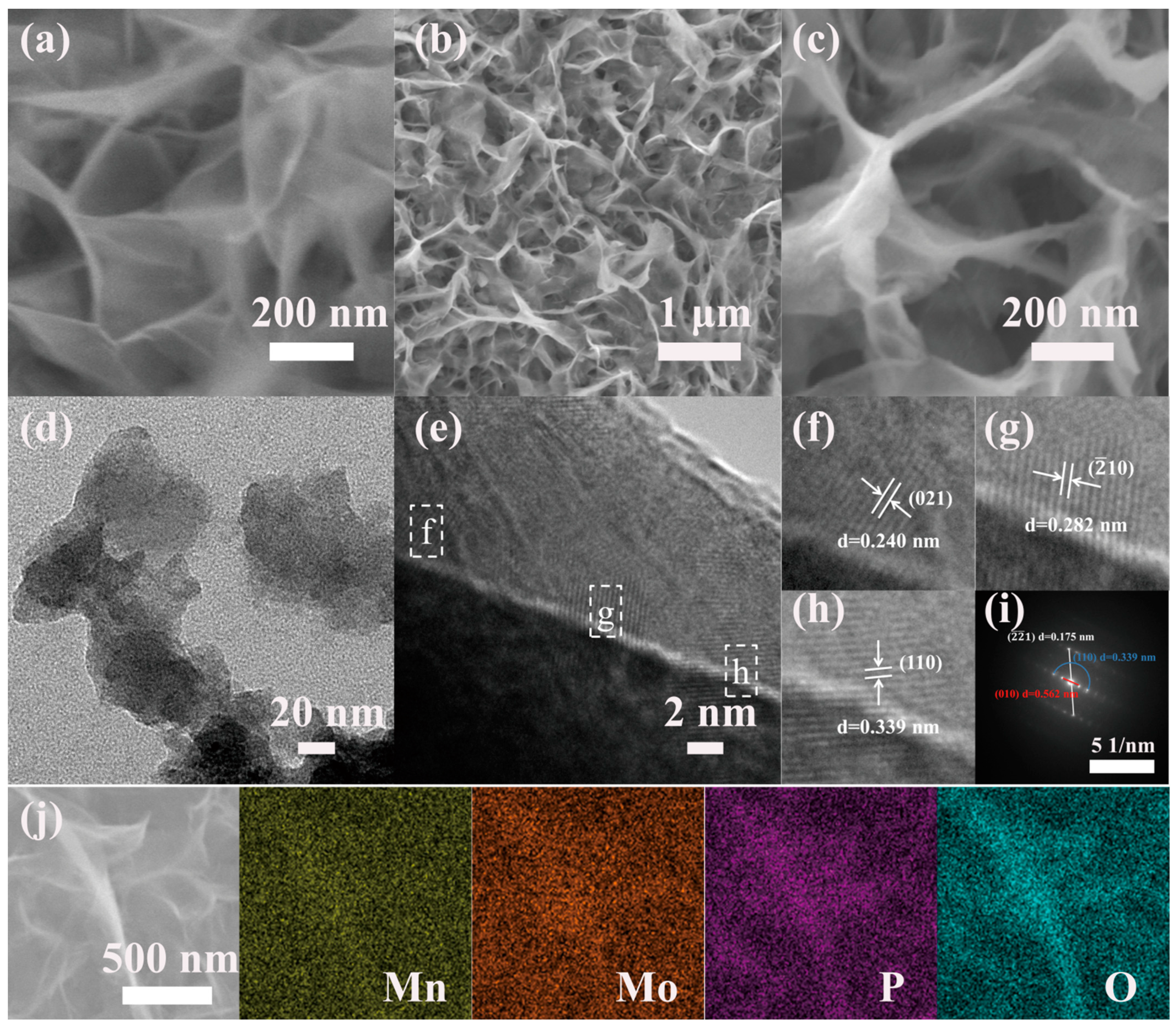
The morphologies of the MnMoO4·H2O and P–MnMoO4 nanosheets were analyzed by SEM. Before phosphorylation, manganese molybdate presents as a dense, uniform, vertically aligned array of nanosheets on the surface of NF. The cores of MnMoO4·H2O nanosheets present a regular morphology and crosslinking structure without aggregation (Figure 2a). This architecture minimizes the electrode material’s inactive volume and enhances the electron conduction efficiency during electrochemical processes. Figure 2b shows that the phosphorus-doped manganese molybdate sample is vertically interconnected, and the addition of phosphorus does not change the original morphological structure of the samples. The skeleton of the nickel foam substrate is covered by a layer of uniformly dense nanosheets. Possibly due to the distribution at the edges of the nickel foam skeleton, some aggregates and nanoflowers appear, which have little effect on the overall morphology, and a small number of nanoflowers can increase the specific surface area and improve the electrochemical properties (Figure S1). However, the surface of the nanosheets becomes coarse, and the surface is covered with separated particles producing a large number of marginal sites of small size effects (Figure 2c). These alterations lead to an increased specific surface area of the P–MnMoO4 nanosheets electrode material, enhancing the electrical contact with the electrolyte. Additionally, the incorporation of phosphorus elements enhances the overall electrical conductivity and promotes electrochemical activity.
The nanosheet structure of the P–MnMoO4 nanomaterial was analyzed using TEM images. Figure 2d shows the TEM image of P–MnMoO4, revealing a distinct nanosheet structure. Figure 2e shows the HRTEM image of P–MnMoO4 with clear lattice fringes. The lattice distances of 0.240 nm, 0.282 nm, and 0.339 nm depicted in Figure 2f–h correspond to the (021), (), and (110) planes of the MnMoO4⋅H2O phase, respectively. Figure 2i shows the SAED pattern of P–MnMoO4, indicating its polycrystalline nature with distinct spots and rings. The SAED pattern matches the (1), (110), and (010) planes of MnMoO4⋅H2O, indicating that a small amount of phosphorus doping does not affect the MnMoO4⋅H2O nanosheet substrate. To ascertain the elemental composition of the experimental samples, EDS scans were conducted on the doped samples. Figure 2j shows the P–MnMoO4 scanning the EDS diagram at the magnification surface. Mn, Mo, O, and P are evenly dispersed across the nickel foam’s surface. The successful doping of phosphorus atoms into manganese molybdate was demonstrated.
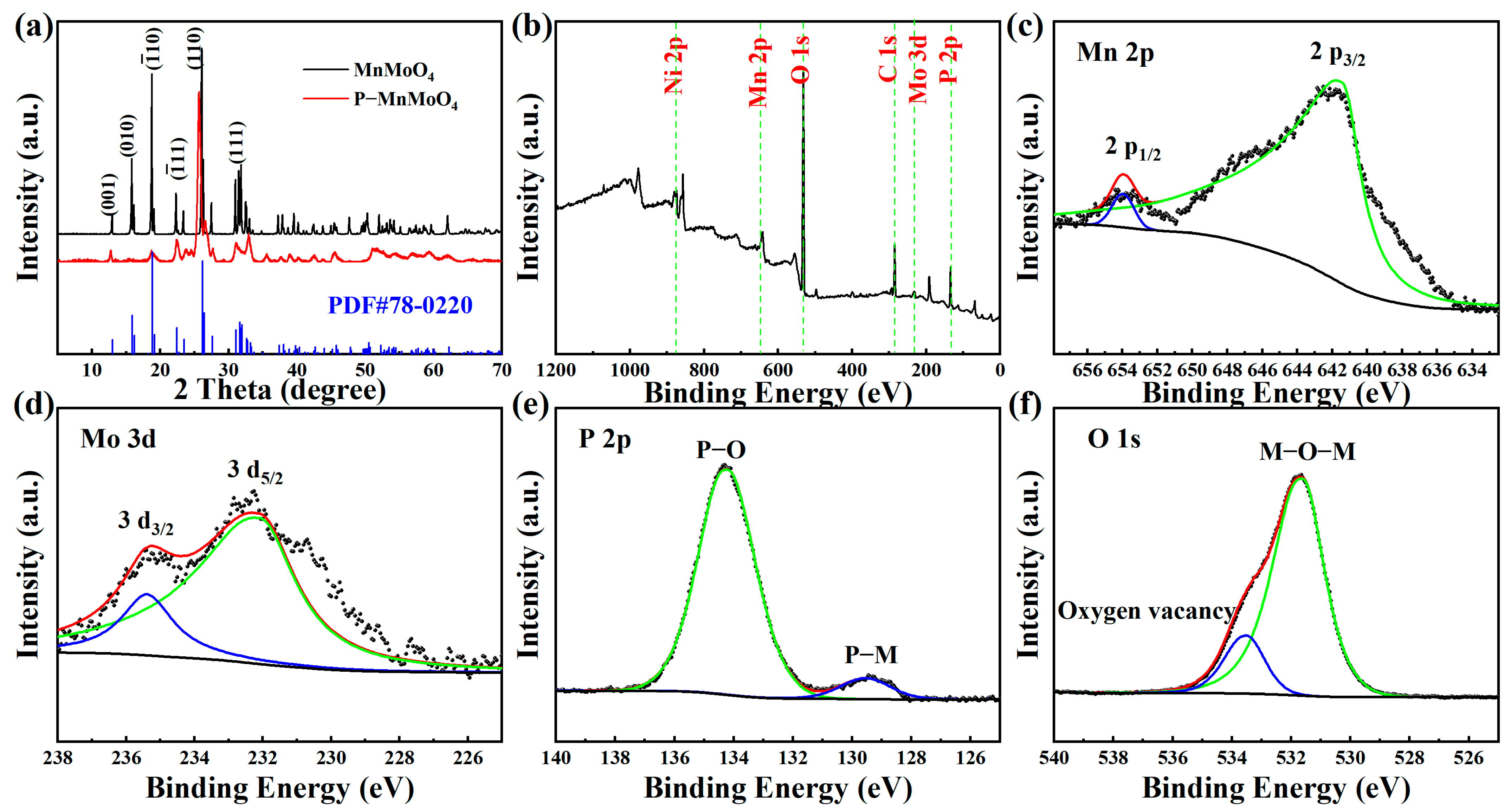
To examine the crystal structure and composition of the samples, XRD analysis was conducted on the prepared MnMoO4·H2O and P–MnMoO4 nanosheets, as depicted in Figure 3a. Because the X-ray diffraction peak of nickel is rather strong and the amount of MnMoO4·H2O grown in situ is low, the active material was first scraped off from the nickel foam, and the scraped nickel monomers were absorbed with a magnet for XRD testing. The diffraction peaks of MnMoO4·H2O grown in situ by the hydrothermal method are consistent with the standard triclinic MnMoO4·H2O (JCPDS card No.78–0220) [27]. Among them, the characteristic peaks with 2θ of 12.92°, 15.94°, 18.79°, 26.28°, and 31.98° correspond to the (001), (010), (), (110), and (111) crystal plane diffractions of MnMoO4·H2O, respectively. Meanwhile, the high and fine diffraction peaks of MnMoO4·H2O indicate better crystallinity.
The diffraction pattern of P–MnMoO4 did not change significantly, indicating that only a small amount of phosphorus was doped during the gas–solid reaction. The diffraction peaks of P–MnMoO4 at 12.71°, 18.74°, 25.65°, and 31.87° correspond to the (001), (), (110), and (111) crystal plane diffractions of MnMoO4·H2O, respectively. It shows that the structure of manganese molybdate is not changed after phosphorylation, which is consistent with the SEM results. The synthesized material is uniform in composition rather than being composite. The low and broad diffraction peaks of P–MnMoO4 compared to those of MnMoO4·H2O indicate that poorer crystallinity was obtained. This difference may be caused by P doping, in which the larger radius P elements partially replace the original position of O, which may lead to a slight change in the crystallinity [28], and no additional diffraction peaks appeared, indicating that the doping of the P element did not change the original crystal structure.
To gain a more thorough insight into the elemental composition and chemical states of P–MnMoO4 nanosheets, XPS analysis was performed. The XPS (Figure 3b) of P–MnMoO4 demonstrated the existence of Mo, Mn, P, and O elements. The binding energy peaks at 653.73 eV and 641.40 eV are attributed to Mn 2p1/2 and Mn 2p3/2, respectively (Figure 3c). The energy gap between these two peaks is 12.33 eV, suggesting the presence of Mn2+ [29,30]. In Figure 3d, the binding energy peaks at 235.45 eV and 231.74 eV are attributed to Mo 3d3/2 and Mo 3d5/2, respectively. The energy gap between these two peaks is 3.71 eV, suggesting the presence of Mo6+ [31,32]. In Figure 3e, the P 2p core energy level spectrum reveals two peaks with binding energies of 134.14 eV and 129.48 eV, corresponding to the P–O bond (phosphide signal peak) and the phosphorus–metal bond, respectively [21,33]. The binding energy peaks at 533.25 eV and 531.60 eV in Figure 3f correspond to the characteristic peaks of the oxygen vacancies and metal–oxygen bonds, respectively [20,34]. There was no significant change observed in the chemical state in the P 2p spectra, suggesting the structural stability of the material. These findings further confirm the successful doping of elemental P into the MnMoO4 nanosheets, which are also indicated by the results of the XRD test described previously.
2.2. Electrochemical Characterizations
Through prior research experience, the optimal hydrothermal reaction time and temperature conditions were determined for the preparation of the precursor MnMoO4·H2O nanosheets using the hydrothermal method. The experimental conditions of 150 °C and 8 h are used to generate MnMoO4·H2O nanosheets of favorable microscopic morphology and pore size for good contact between the electrolyte and active material [20,35]. In the gas–solid reaction method, the thermal decomposition of NaH2PO2·H2O produces PH3 gas and water vapor present in the tube furnace. Driven by argon, PH3 gas moves to the surface of manganese molybdate and reacts with it to form phosphoric acid. A small amount of phosphoric acid is gradually “acid dissociated” in the presence of water vapor to produce and in turn. Then, and undergo ion exchange on the surface of MnMoO4−4x, diffuses outward, and penetrates inward slowly to realize the phosphorus doping. The specific reaction equations are as follows:
NaH2PO2·H2O→PH3↑ + Na2HPO4 + H2O↑
MnMoO4 + xPH3 = MnMoO4−4x + xH3PO4
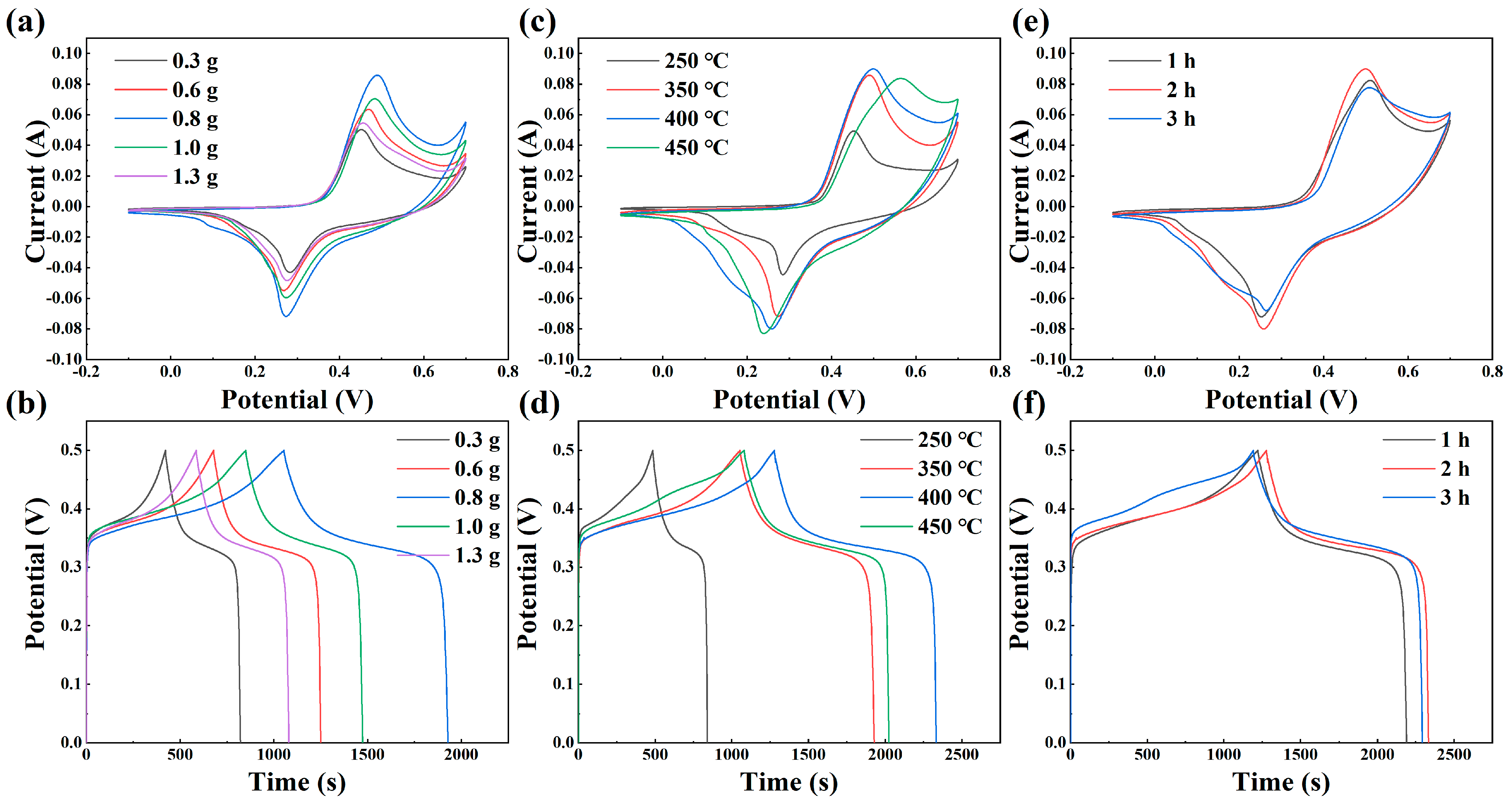
In order to determine the optimal phosphorylation reaction conditions, three parameters were studied in terms of the amount of phosphorus source, phosphorylation temperature, and phosphorylation time, respectively. Subsequently, CV and GCD tests were performed to evaluate the impact of these parameters on the electrochemical properties resulting from the phosphorylation reaction. Figure 4a depicts the CV curves of the phosphorylated manganese molybdate electrode at 20 mV s−1 for varying phosphorus source quantities: 0.3 g, 0.6 g, 0.8 g, 1.0 g, and 1.3 g. Observably, the curve corresponding to a hypophosphite quantity of 0.8 g covers a larger enclosed area and demonstrates a higher capacitance area ratio. The mass ratio of the precursor to phosphorus source ranges from 1:10 to 1:40 or even higher [36,37]. From the preliminary experiments, the electrochemical properties of P–MnMoO4/NF generated by the gas phase reaction were not significantly improved when the content of the phosphorus source (NaH2PO2) was lower than 0.3 g. The electrochemical properties of P–MnMoO4/NF generated by the gas phase reaction were not significantly improved. If the content of the phosphorus source is too much and too high, it may lead to the accumulation of the phosphorus source (NaH2PO2) before the decomposition reaction, which leads to the ineffective improvement of the electrochemical performance and, at the same time, causes a large amount of phosphorus resources to be wasted. Figure 4b illustrates the GCD curves of the electrodes (0–0.5 V) following the phosphorylation of manganese molybdate with different phosphorus source amounts at 1 mA cm−2. The amount of hypophosphite is 0.8 g for the longest discharge time and higher charging and discharging plateau voltage, so it is determined that 0.8 g is the optimal amount of sodium hypophosphite for the phosphorus source.
The effect of the phosphorylation temperature on the experimental results was studied based on the phosphorus source content of 0.8 g and the temperatures of 250 °C, 350 °C, 400 °C, and 450 °C, respectively. Figure 4c illustrates the CV plots of the three samples at different temperatures at a 20 mV s−1 scan rate. It can be seen that P–MnMoO4 are pseudocapacitor materials at three different temperatures, but there is little difference in the wrapping area of the CV curves at 400 °C and 450 °C. Constant current charge and discharge are tested and shown in Figure 4d, in which the GCD curve of 400 °C has the longest discharge time, so the optimal phosphorylation reaction temperature is determined to be 400 °C. The experiments to determine the phosphorylation time were conducted under the condition of 0.8 g sodium hypophosphite and a reaction temperature of 400 °C. The reaction durations chosen were 1 h, 2 h, and 3 h, respectively. CV and GCD tests were conducted at identical scan rates and current densities, respectively (Figure 4e,f). The area enclosed by the CV curves is difficult to directly assess, indicating that the phosphorylation time has minimal impact on the electrochemical performance. The GCD curves were measured to quantitatively analyze the respective specific capacitance, and the optimal phosphorylation reaction time of 2 h was subsequently determined. In summary, the ideal parameters for the phosphorylation experiment were 0.8 g of sodium hypophosphite, a reaction temperature of 400 °C, and a reaction time of 2 h. The electrochemical performance of P–MnMoO4 and MnMoO4·H2O prepared under the optimal experimental conditions was compared.
We compared the electrochemical performance of the P–MnMoO4 electrode (0.8 g, 400 °C, 2 h) prepared with the optimal parameters separately with that of the MnMoO4·H2O electrode. Detailed CV and GCD curves for the MnMoO4·H2O and P–MnMoO4 electrode materials at different scan rates and current densities are shown in Figures S2 and S3. The area specific capacitances of the MnMoO4·H2O electrodes are 0.657, 0.634, 0.605, 0.550, 0.505, 0.451, and 0.400 F cm−2 at current densities of 1, 2, 3, 5, 10, 15, and 20 mA cm−2. The CV curves of the P–MnMoO4 electrode (0.8 g, 400 °C, 2 h) at various scanning rates exhibited minimal change in curve morphology, suggesting excellent reversibility of the electrode.
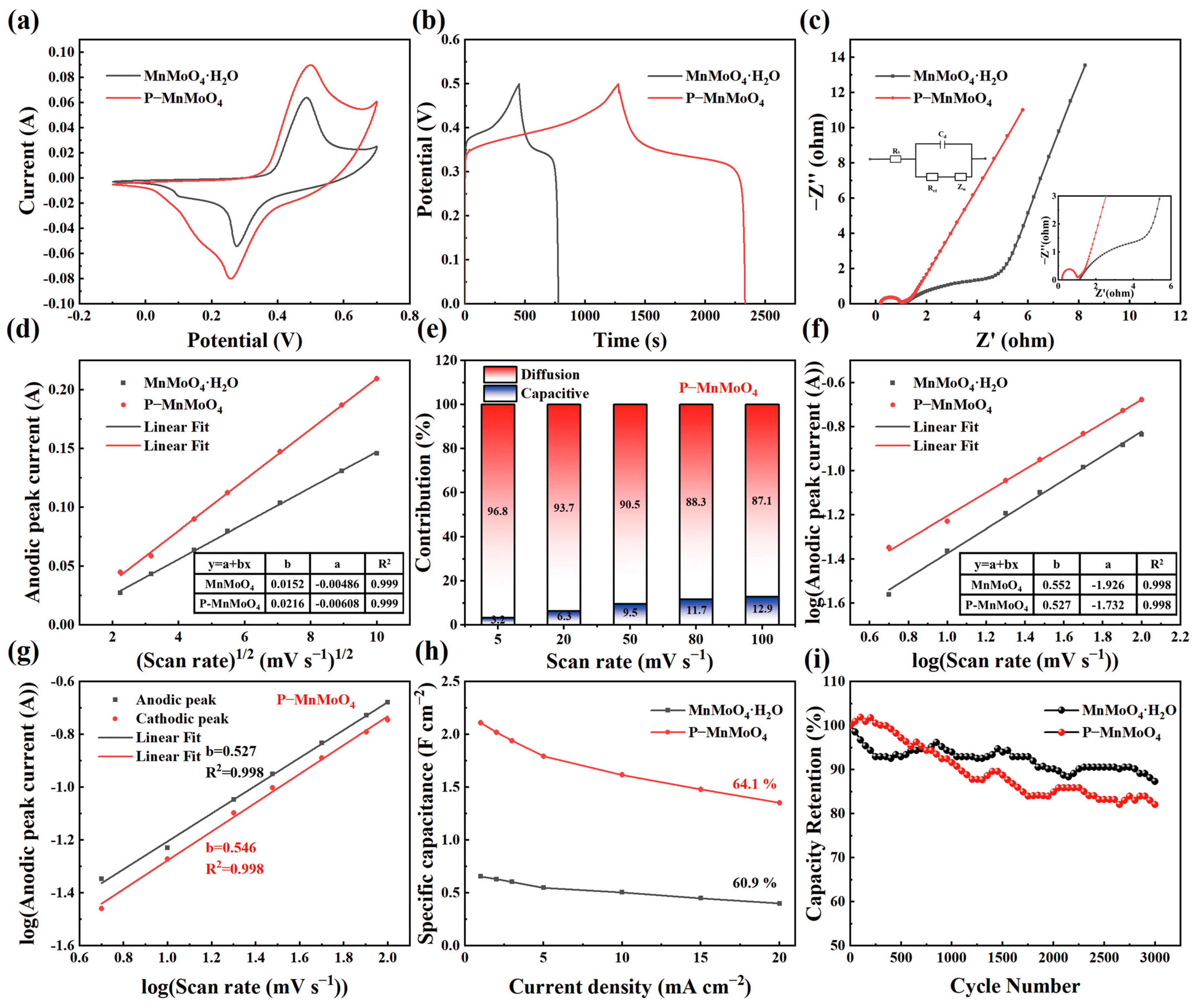
Figure 5a depicts the CV curves of the P–MnMoO4 and MnMoO4·H2O electrodes within the potential range of −0.1 to 0.7 V at a scanning rate of 20 mV s−1. The enclosed area of the CV curve for the P–MnMoO4 electrode exceeds that of the MnMoO4·H2O electrode, indicating that P–MnMoO4 can store more charge and has better electrochemical performance, mainly attributed to the addition of phosphorus elements. Both CV curves exhibit a pair of well-defined redox peaks, indicative of Faraday reactions associated with electrochemical capacitance. In Figure 5b, the GCD curves of the P–MnMoO4 and MnMoO4·H2O electrodes are shown, measured at 1 mA cm−2. The discharge time of the P–MnMoO4 electrode (1054 s) notably surpasses that of the MnMoO4·H2O electrode (327 s). At 1 mA cm−2, the specific capacitance of P–MnMoO4 is 2.112 F cm−2, approximately 3.2 times greater than that of the MnMoO4·H2O electrode (0.657 F cm−2). The two electrodes both exhibit charge/discharge plateaus, indicating the pseudocapacitive characteristics of the active material. In Figure 5c, Nyquist plots of the P–MnMoO4 and MnMoO4·H2O electrodes are displayed, with the inset illustrating the equivalent circuit diagram. Since both materials are grown on nickel foam, the contact resistance is minimal and manifests at the intersection of the impedance curve with the horizontal axis. The radius of the curvature of P–MnMoO4 in the high-frequency region is smaller than that of MnMoO4·H2O, indicating a reduced charge transfer resistance. In the low-frequency region, a linear trend with a slope close to 1 represents the Warburg impedance, reflecting the efficiency of electrolyte ion transfer at the electrode surface and in solution. The findings indicate that the internal resistance (Rs = 0.198 Ω) and charge transfer resistance (Rct = 0.735 Ω) of P–MnMoO4 are lower than those of MnMoO4·H2O (internal resistance (Rs = 1.121 Ω) and charge transfer resistance (Rct = 5.398 Ω)), attributed to the incorporation of phosphorus to enhance the overall conductivity of the electrode material.
Figure 5d shows that the corresponding currents of the redox peaks of the P–MnMoO4 and MnMoO4·H2O electrodes are roughly linear with the one-half order of the sweep speed. It shows that the energy storage of the P–MnMoO4 and MnMoO4·H2O electrodes is mainly carried out by the redox reaction inside the electrode material, not only by the surface redox reaction [38]. The P–MnMoO4 electrode has a larger slope of the fitted line (b = 0.0216), indicating a high ion migration rate. Indirectly, it is proven that the phosphorus element is doped into the interior of MnMoO4·H2O and participates in the redox reaction, possibly forming oxygen vacancies or phosphorus atoms replacing oxygen atoms. Figure 5e shows the contribution rates of the surface-controlled and diffusion-controlled capabilities of the P–MnMoO4 electrode at different scan rates. As the scan rates increase, the surface-controlled capabilities become more prominent due to the suppression of ion diffusion [39]. However, at 100 mV s−1, the diffusion-controlled reaction capacitance remains dominant at 87.3%, indicating that the fast redox reaction process of the P–MnMoO4 electrode in electrochemical reactions is less affected by the scan rate, corresponding to the high ion migration rate. Figure 5f illustrates the fitting line of log (i) versus log (v) collected from the CV curve of various electrodes. The constant of the P–MnMoO4 electrode is 0.527, closer to 0.5, revealing that the P–MnMoO4 electrode is a typical diffusion-controlled Faraday reaction. In Figure 5g, the fitting b values of the oxidation and reduction peaks of the P–MnMoO4 electrode are displayed, both approaching 0.5. This suggests excellent reversibility in the redox reaction of the P–MnMoO4 electrode, facilitating rapid and reversible electron transfer at the interface between the electrode material and the electrolyte.
Area-specific capacitances for the P–MnMoO4 and MnMoO4·H2O electrodes were computed from the GCD curves at various current densities (Figure 5h). As the current density increased, the specific capacitance of both the P–MnMoO4 and MnMoO4·H2O electrodes decreased. Due to the rapid decrease in the charge/discharge time at higher charge/discharge rates, the movement of ions is restricted and the ions cannot reach the interior of the electrode material in a short time, and the redox and ion intercalation reactions occur incompletely [40]. As the current density increased from 1 mA cm−2 to 20 mA cm−2, the specific capacitance retention of the P–MnMoO4 electrode was 64.1%, which was higher than that of the MnMoO4·H2O electrode (60.9%). The P–MnMoO4 and MnMoO4·H2O electrodes were charged and discharged 3000 times at 5 mA cm−2 (Figure 5i). After 3000 charge/discharge cycles, the specific capacitance retention rate of P–MnMoO4 was 82.1%, slightly lower than that of the MnMoO4·H2O electrode (87.3%). The nanosheet morphology of the P–MnMoO4 electrode material does not change after long-term cycling (Figure S4). The decrease in capacity retention after multiple charge/discharge cycles is mainly due to the possible slight exfoliation of the nanosheet structure of the electrode material and the change in electrolyte concentration during long cycling. Nonetheless, the specific capacity after cycling of the P–MnMoO4 electrode remains higher than the specific capacity before cycling of the MnMoO4·H2O electrode. Overall, the P–MnMoO4 electrode material still demonstrates favorable cycling stability.
2.3. P–MnMoO4//AC ASC Testing
To evaluate P–MnMoO4’s practical utility, we constructed an asymmetric supercapacitor device with P–MnMoO4 serving as the positive electrode and activated carbon (AC) as the negative electrode, 2 M KOH as the electrolyte, and cellulose paper as the diaphragm (Figure 6a). Detailed CV and GCD curves for commercial activated carbon (AC) anode electrode materials are given in Figure S5, and the CV curves are quasi-rectangular in shape, which is a double electric layer capacitance characteristic. In the three-electrode test regime, Figure 6b shows the CV curves measured at 20 mV s−1 for P–MnMoO4 and activated carbon, respectively. The absence of overlap between the individual CV curve regions of the positive and negative electrodes within the potential window confirms the precise alignment of the two electrodes during the assembly of the asymmetric supercapacitor [41]. To establish the voltage window of the device, we expanded the voltage range of the CV curve from 0–0.8 V to 0–1.8 V at a scan rate of 20 mV s−1 (Figure 6c). There was no significant polarization in the 0–1.6 V range, and the P–MnMoO4//AC device was CV tested at scan rates of 10 to 100 mV s−1 during this voltage window (Figure 6d). As the scan rate increases, all CV curve shapes do not change due to the increase in scan speed, and they are irregularly rectangular in shape. Both pseudocapacitors and double-layer capacitors contribute to this asymmetric supercapacitor device [42]. Figure 6e shows the GCD curve that indicates the maximum voltage window, which is obtained by incrementing the voltage from 0 to 0.8 V with a step of 0.2 V at 5 mA cm−2. If the GCD test is performed above the 1.6 V voltage window, it will cause the device to remain in the charging state rather than be discharged, and a higher voltage window will not be achieved. The CV and GCD tests incremented the voltage window, and the final test results were consistent, identifying the device voltage window as 0–1.6 V. Figure 6f shows the variation of the GCD curve of P–MnMoO4//AC as the current density increases from 5 mA cm−2 to 30 mA cm−2 within the voltage range of 0–1.6 V. The symmetrical shapes of the CV and GCD curves of the devices tested at different scanning speeds and current densities indicate that the two electrode materials are well matched and have excellent charge/discharge reversibility [38].
The power and energy density of the P–MnMoO4//AC ASC device can be computed using Equations (7) and (8). The energy density of P–MnMoO4//AC was 41.9, 34.8, 27.6, 25.3, and 21.2 Wh kg−1 for power densities of 666.8, 1348.8, 2015.4, 2751.7, and 4128.3 W kg−1, respectively. The capacity retention of the P–MnMoO4//AC ASC device was 84.5% after 10,000 cycles, and the Coulombic efficiency remained nearly 100% throughout each charge/discharge cycle, with the initial increase in capacity during the cycling period likely attributable to the activation process of the electrode material (Figure 7). When compared to other asymmetric supercapacitors comprising MnMoO4 material and activated carbon, the P–MnMoO4//AC supercapacitor demonstrates superior energy density at equivalent power densities and exhibits outstanding cycling stability (Table S1). The results imply the possibility of practical applications of phosphorus-doped manganese molybdate in energy storage devices.
3. Materials and Methods
3.1. Chemicals and Materials
The reagents included Na2MoO4·2H2O, MnSO4·H2O, NaH2PO2·H2O, anhydrous ethanol, KOH, HCl, CH3COCH3, NF, commercial active carbon, acetylene black, polyvinylidene fluoride (PVDF), and N–methyl pyrrolidone, purchased from Sinopharm Chemical Reagents Co. Ltd. (Shanghai, China). The 1 mm thick Ni foams were trimmed into pieces measuring 1 cm × 1.5 cm for ease of handling. Subsequently, they were immersed in 1 M HCl solution and acetone for ultrasonic cleaning for 15 min to eliminate NiO and organic contaminants from the surface. Afterwards, the pretreated Ni foams underwent thorough rinsing with deionized water and ethanol before being vacuum-dried at 60 °C for 12 h. All reagents utilized were of analytical grade and necessitated no further purification.
3.2. Synthesis of MnMoO4·H2O Precursors and P–MnMoO4
In a typical synthesis, 2 mmol of Na2MoO4·2H2O and 2 mmol of MnSO4·H2O were dissolved separately in 40 mL of deionized water. The mixed solution and clean Ni foam were then transferred into a 100 mL stainless steel autoclave and placed in a blast-drying oven at 150 °C for 8 h. After the reaction was completed, the samples were cooled to room temperature, gently rinsed with deionized water to prevent detachment of the grown MnMoO4·H2O from the nickel foam, and subsequently dried at 60 °C for 12 h.
The doping of the phosphorus element was achieved using a gas–solid reaction method. MnMoO4·H2O/NF and NaH2PO2·H2O were placed in the porcelain boat, with NaH2PO2·H2O positioned upstream and MnMoO4·H2O/NF downstream. Then, it was placed in a tube furnace, heated with argon gas to a certain temperature for a certain period of time, and then cooled to room temperature to obtain P–MnMoO4/NF. In this paper, we proposed the optimization of the experimental parameters of the phosphorus source (0.3 g, 0.6 g, 0.8 g, 1.0 g, and 1.3 g); phosphating temperature (250 °C, 350 °C, 400 °C, and 450 °C); and phosphating time (1 h, 2 h, and 3 h) to generate P–MnMoO4. The mass of active material on NF of the MnMoO4·H2O and P–MnMoO4 (0.8 g, 400 °C, 2 h) samples was about 1 mg cm−2 and 1.2 mg cm−2, respectively, measured by an electronic balance.
3.3. P–MnMoO4//AC Asymmetric Supercapacitor Assembly
Activated carbon (AC), conductive carbon black, and polyvinylidene fluoride (PVDF) were mixed in a mass ratio of 8:1:1 and combined with an appropriate amount of N–methylpyrrolidone. The mixture was stirred into a paste at room temperature and then uniformly applied to clean Ni foam to prepare the negative electrode of the device. This asymmetric device was assembled at room temperature and in air and used for the two-electrode test. The amount of AC required was calculated according to Equation (5) [43]:
where m (g), C (F cm−2), and ΔV (V) represent the mass of electrode material, specific capacitance, and potential window, respectively.
3.4. Characterization of Materials
The nanostructured morphologies of the samples were examined using a scanning electron microscope (SEM, ZEISS Gemini 300, Jena, Germany). Elemental mapping imaging was performed using energy dispersive X-ray spectroscopy (EDS, Horiba EMAX Energy, EX-350, Kyoto, Japan). Transmission electron microscopy (TEM), high-resolution transmission electron microscopy (HRTEM), and selected area electron diffraction (SAED) images were obtained with a FEI-TALOS-F200X (Thermo Fisher Scientific, Waltham, MA, USA). The crystal structure of the samples was analyzed using an X-ray powder diffractometer (XRD, Empyrean, Malvern Panalytical B.V, Almelo, The Netherlands) with graphite monochromatic Cu Kα irradiation. The chemical compositions of the nanocomposites were analyzed using X-ray photoelectron spectroscopy (XPS, American Thermo Fisher Scientific K-Alpha, USA).
3.5. Electrochemical Measurements
All electrochemical measurements were performed using an electrochemical workstation (CHI 660D). Samples of MnMoO4·H2O and P–MnMoO4 electrode materials prepared on Ni foam were directly used as working electrodes for the three-electrode test, and Pt net and Hg/HgO electrodes were used as counter and reference electrodes in 2 M KOH aqueous electrolytes. The specific capacitance of the single and full electrode devices were calculated using Equation (6) [44]:
where I (A) is the discharge current, Δt (s) is the discharge time, m (g) is the mass loading of the active material, ΔV is the operating voltage, and (F g−1) is the mass ratio capacitance. When its m (g) is replaced with the effective area of the electrode, Equation (6) can be used for the calculation of the area ratio capacitance (F cm−2).
To calculate the energy and power density of the asymmetric supercapacitor, the following Equations (7) and (8) were used [45]:
where E (Wh kg−1) is the energy density, P (W kg−1) stands for the power density, C (F g−1) is the specific capacitance, (V) is the operating voltage window, and Δt (s) is the discharge time.
4. Conclusions
In this research, MnMoO4·H2O nanosheets were initially synthesized on nickel foam via a hydrothermal approach, followed by the introduction of phosphorus into the MnMoO4·H2O nanosheets using a gas–solid reaction method. The experimental parameters of the phosphorus source content, reaction temperature, and reaction duration were optimized for phosphorylation. The phosphorylated manganese molybdate nanosheets were characterized and electrochemically measured. The P–MnMoO4 of the preferred electrochemical properties were achieved when the phosphorus source content was 0.8 g, the heating temperature was 400 °C, and the heating time was 2 h. At l mA cm−2, the specific capacitance of P–MnMoO4 was 2.112 F cm−2, approximately 3.2 times greater than that of the MnMoO4·H2O electrode. Following 3000 charge/discharge cycles at 5 mA cm−2, the specific capacitance of P–MnMoO4 remained at approximately 82.1% of its initial value. Phosphorus doping enhances the charge storage, conductivity, and ion migration rate of MnMoO4 while preserving the nanosheet morphology of MnMoO4. P–MnMoO4//AC devices provide a high energy density of 41.9 Wh kg−1 at a power density of 666.8 W kg−1, with 84.5% capacity retention after 10,000 charge/discharge cycles. This work shows that the P–MnMoO4 material is a potential electrode material with extensive applications in building high-performance energy storage devices.
Supplementary Materials
The following Supplementary Materials can be downloaded at https://0-www-mdpi-com.brum.beds.ac.uk/article/10.3390/molecules29091988/s1: Figure S1. SEM images of (a,b) NF, (c,d) MnMoO4·H2O, and (e,f) P–MnMoO4; Figure S2. (a) CV curve of MnMoO4·H2O; (b) GCD curve; Figure S3. (a) CV curve of P–MnMoO4; (b) GCD curve; Figure S4. (a–c) SEM images of the P–MnMoO4 electrode material after charge/discharge cycles; Figure S5. (a) CV curve of activated carbon; (b) GCD curve; Table S1. Performance comparison of the hybrid supercapacitor based on the MnMoO4 electrode material with other reported devices. Refs. [46,47,48,49,50,51] are cited in the Supplementary Materials.
Author Contributions
Conceptualization, K.W. and G.L.; Methodology, K.W. and Y.L. (Yan Li); Data curation, K.W. and Y.L. (Yan Li); Writing–original draft, Y.L. (Yu Liu) and Z.L.; Writing–review and editing Y.L. (Yu Liu), Y.L. (Yan Li), T.F. and H.L.; Supervision, K.W. and G.L. All authors have read and agreed to the published version of the manuscript.
Funding
This research was financially supported by the National Natural Science Foundation of China (Grant Nos. U1810204, 61901293, 22002083, 61975072, 12174173, and 21905099); Natural Science Foundation of Shanxi Province, China (Grant No. 201901D111099); Natural Science Foundation of Fujian Province, grant numbers 2022H0023, 2022J02047, and 2022G02006; and the University Science and Technology Innovation Project of Shanxi Province (Grant No.2019L0316). The author K.W. acknowledges the research grants from EEA (European Economic Area)-Norway-Romania Project Graftid, RO-NO-2019-0616 and EEA-Poland-NOR/POLNORCCS/PhotoRed/0007/2019-00.
Institutional Review Board Statement
Not applicable.
Informed Consent Statement
Not applicable.
Data Availability Statement
The data presented in this study are available in the article.
Conflicts of Interest
The authors declare no conflicts of interest.
References
- Zou, C.; Zhao, Q.; Zhang, G.; Xiong, B. Energy revolution: From a fossil energy era to a new energy era. Nat. Gas Ind. B 2016, 3, 1–11. [Google Scholar] [CrossRef]
- Raza, W.; Ali, F.; Raza, N.; Luo, Y.; Kim, K.-H.; Yang, J.; Kumar, S.; Mehmood, A.; Kwon, E.E. Recent advancements in supercapacitor technology. Nano Energy 2018, 52, 441–473. [Google Scholar] [CrossRef]
- Libich, J.; Máca, J.; Vondrák, J.; Čech, O.; Sedlaříková, M. Supercapacitors: Properties and applications. J. Energy Storage 2018, 17, 224–227. [Google Scholar] [CrossRef]
- Yang, H.; Kannappan, S.; Pandian, A.S.; Jang, J.H.; Lee, Y.S.; Lu, W. Graphene supercapacitor with both high power and energy density. Nanotechnology 2017, 28, 445401. [Google Scholar] [CrossRef] [PubMed]
- Chodankar, N.R.; Pham, H.D.; Nanjundan, A.K.; Fernando, J.F.S.; Jayaramulu, K.; Golberg, D.; Han, Y.K.; Dubal, D.P. True Meaning of Pseudocapacitors and Their Performance Metrics: Asymmetric versus Hybrid Supercapacitors. Small 2020, 16, e2002806. [Google Scholar] [CrossRef] [PubMed]
- Lim, E.; Jo, C.; Lee, J. A mini review of designed mesoporous materials for energy-storage applications: From electric double-layer capacitors to hybrid supercapacitors. Nanoscale 2016, 8, 7827–7833. [Google Scholar] [CrossRef] [PubMed]
- Han, Y.; Dai, L. Conducting Polymers for Flexible Supercapacitors. Macromol. Chem. Phys. 2019, 220, 1800355. [Google Scholar] [CrossRef]
- Najib, S.; Erdem, E. Current progress achieved in novel materials for supercapacitor electrodes: Mini review. Nanoscale Adv. 2019, 1, 2817–2827. [Google Scholar] [CrossRef]
- Zhang, Y.; Mei, H.-X.; Cao, Y.; Yan, X.-H.; Yan, J.; Gao, H.-L.; Luo, H.-W.; Wang, S.-W.; Jia, X.-D.; Kachalova, L.; et al. Recent advances and challenges of electrode materials for flexible supercapacitors. Coord. Chem. Rev. 2021, 438, 213910. [Google Scholar] [CrossRef]
- Dai, M.; Zhao, D.; Wu, X. Research progress on transition metal oxide based electrode materials for asymmetric hybrid capacitors. Chin. Chem. Lett. 2020, 31, 2177–2188. [Google Scholar] [CrossRef]
- Movassagh-Alanagh, F.; Bordbar-Khiabani, A.; Ahangari-Asl, A. Fabrication of a ternary PANI@Fe3O4@CFs nanocomposite as a high performance electrode for solid-state supercapacitors. Int. J. Hydrogen Energy 2019, 44, 26794–26806. [Google Scholar] [CrossRef]
- Ryu, I.; Kim, D.; Choe, G.; Jin, S.; Hong, D.; Yim, S. Monodisperse RuO2 nanoparticles for highly transparent and rapidly responsive supercapacitor electrodes. J. Mater. Chem. A 2021, 9, 26172–26180. [Google Scholar] [CrossRef]
- Zheng, D.; Zhao, F.; Li, Y.; Qin, C.; Zhu, J.; Hu, Q.; Wang, Z.; Inoue, A. Flexible NiO micro-rods/nanoporous Ni/metallic glass electrode with sandwich structure for high performance supercapacitors. Electrochim. Acta 2019, 297, 767–777. [Google Scholar] [CrossRef]
- Zhong, R.; Xu, M.; Fu, N.; Liu, R.; Zhou, A.A.; Wang, X.; Yang, Z. A flexible high-performance symmetric quasi-solid supercapacitor based on Ni-doped MnO2 nano-array @ carbon cloth. Electrochim. Acta 2020, 348, 136209. [Google Scholar] [CrossRef]
- Liang, R.; Du, Y.; Xiao, P.; Cheng, J.; Yuan, S.; Chen, Y.; Yuan, J.; Chen, J. Transition Metal Oxide Electrode Materials for Supercapacitors: A Review of Recent Developments. Nanomaterials 2021, 11, 1248. [Google Scholar] [CrossRef] [PubMed]
- Zhu, Z.; Sun, Y.; Li, C.; Yang, C.; Li, L.; Zhu, J.; Chou, S.; Wang, M.; Wang, D.; Li, Y. Mini-review: Progress on micro/nanoscale MnMoO4 as an electrode material for advanced supercapacitor applications. Mater. Chem. Front. 2021, 5, 7403–7418. [Google Scholar] [CrossRef]
- Watcharatharapong, T.; Minakshi Sundaram, M.; Chakraborty, S.; Li, D.; Shafiullah, G.M.; Aughterson, R.D.; Ahuja, R. Effect of Transition Metal Cations on Stability Enhancement for Molybdate-Based Hybrid Supercapacitor. ACS Appl. Mater. Interfaces 2017, 9, 17977–17991. [Google Scholar] [CrossRef] [PubMed]
- Li, L.; Wang, L.; Zhang, C. Hierarchical MnMoO4@nitrogen-doped carbon core-shell microspheres for lithium/potassium-ion batteries. J. Alloys Compd. 2022, 893, 162336. [Google Scholar] [CrossRef]
- Mu, X.; Zhang, Y.; Wang, H.; Huang, B.; Sun, P.; Chen, T.; Zhou, J.; Xie, E.; Zhang, Z. A high energy density asymmetric supercapacitor from ultrathin manganese molybdate nanosheets. Electrochim. Acta 2016, 211, 217–224. [Google Scholar] [CrossRef]
- Fu, H.; Wang, M.; Ma, Q.; Wang, M.; Ma, X.; Ye, Y. MnMoO4-S nanosheets with rich oxygen vacancies for high-performance supercapacitors. Nanoscale Adv. 2022, 4, 2704–2712. [Google Scholar] [CrossRef]
- Meng, Y.; Sun, P.; He, W.; Teng, B.; Xu, X. Uniform P doped Co-Ni-S nanostructures for asymmetric supercapacitors with ultra-high energy densities. Nanoscale 2019, 11, 688–697. [Google Scholar] [CrossRef] [PubMed]
- Zhang, Q.; Feng, L.; Liu, Z.; Jiang, L.; Lan, T.; Zhang, C.; Liu, K.; He, S. High Rate Performance Supercapacitors Based on N, O Co-Doped Hierarchical Porous Carbon Foams Synthesized via Chemical Blowing and Dual Templates. Molecules 2023, 28, 6994. [Google Scholar] [CrossRef] [PubMed]
- Yu, J.; Li, Z.; Liu, T.; Zhao, S.; Guan, D.; Chen, D.; Shao, Z.; Ni, M. Morphology control and electronic tailoring of CoxAy (A = P, S, Se) electrocatalysts for water splitting. Chem. Eng. J. 2023, 460, 141674. [Google Scholar] [CrossRef]
- Shi, Y.; Zhang, B. Recent advances in transition metal phosphide nanomaterials: Synthesis and applications in hydrogen evolution reaction. Chem. Soc. Rev. 2016, 45, 1529–1541. [Google Scholar] [CrossRef] [PubMed]
- Guo, S.; Tang, Y.; Xie, Y.; Tian, C.; Feng, Q.; Zhou, W.; Jiang, B. P-doped tubular g-C3N4 with surface carbon defects: Universal synthesis and enhanced visible-light photocatalytic hydrogen production. Appl. Catal. B Environ. 2017, 218, 664–671. [Google Scholar] [CrossRef]
- Liu, Q.; Tian, J.; Cui, W.; Jiang, P.; Cheng, N.; Asiri, A.M.; Sun, X. Carbon nanotubes decorated with CoP nanocrystals: A highly active non-noble-metal nanohybrid electrocatalyst for hydrogen evolution. Angew. Chem. Int. Ed. Engl. 2014, 53, 6710–6714. [Google Scholar] [CrossRef]
- Xu, J.; Sun, Y.; Lu, M.; Wang, L.; Zhang, J.; Qian, J.; Liu, X. Fabrication of hierarchical MnMoO4·H2O@MnO2 core-shell nanosheet arrays on nickel foam as an advanced electrode for asymmetric supercapacitors. Chem. Eng. J. 2018, 334, 1466–1476. [Google Scholar] [CrossRef]
- Guan, D.; Shi, C.; Xu, H.; Gu, Y.; Zhong, J.; Sha, Y.; Hu, Z.; Ni, M.; Shao, Z. Simultaneously mastering operando strain and reconstruction effects via phase-segregation strategy for enhanced oxygen-evolving electrocatalysis. J. Energy Chem. 2023, 82, 572–580. [Google Scholar] [CrossRef]
- Cao, Y.; Li, W.; Xu, K.; Zhang, Y.; Ji, T.; Zou, R.; Yang, J.; Qin, Z.; Hu, J. MnMoO 4·4H2O nanoplates grown on a Ni foam substrate for excellent electrochemical properties. J. Mater. Chem. A 2014, 2, 20723–20728. [Google Scholar] [CrossRef]
- Gao, L.; Chen, G.; Zhang, L.; Yan, B.; Yang, X. Engineering pseudocapacitive MnMoO4@C microrods for high energy sodium ion hybrid capacitors. Electrochim. Acta 2021, 379, 138185. [Google Scholar] [CrossRef]
- Nti, F.; Anang, D.A.; Han, J.I. Facile room temperature synthesis and application of MnMoO4·0.9 H2O as supercapacitor electrode material. Mater. Lett. 2018, 217, 146–150. [Google Scholar] [CrossRef]
- Wei, H.; Yang, J.; Zhang, Y.; Qian, Y.; Geng, H. Rational synthesis of graphene-encapsulated uniform MnMoO4 hollow spheres as long-life and high-rate anodes for lithium-ion batteries. J. Colloid Interface Sci. 2018, 524, 256–262. [Google Scholar] [CrossRef] [PubMed]
- Xing, T.; Ouyang, Y.; Chen, Y.; Zheng, L.; Wu, C.; Wang, X. P-doped ternary transition metal oxide as electrode material of asymmetric supercapacitor. J. Energy Storage 2020, 28, 101248. [Google Scholar] [CrossRef]
- Chen, Y.; Yang, W.; Gao, S.; Sun, C.; Li, Q. Synthesis of Bi2MoO6 nanosheets with rich oxygen vacancies by postsynthesis etching treatment for enhanced photocatalytic performance. ACS Appl. Nano Mater. 2018, 1, 3565–3578. [Google Scholar] [CrossRef]
- Saravanakumar, B.; Ramachandran, S.P.; Ravi, G.; Ganesh, V.; Sakunthala, A.; Yuvakkumar, R. Transition mixed-metal molybdates (MnMoO4) as an electrode for energy storage applications. Appl. Phys. A 2018, 125, 6. [Google Scholar] [CrossRef]
- Shi, Y.; Li, M.; Yu, Y.; Zhang, B. Recent advances in nanostructured transition metal phosphides: Synthesis and energy-related applications. Energy Environ. Sci. 2020, 13, 4564–4582. [Google Scholar] [CrossRef]
- Zong, Q.; Liu, C.; Yang, H.; Zhang, Q.; Cao, G. Tailoring nanostructured transition metal phosphides for high-performance hybrid supercapacitors. Nano Today 2021, 38, 101201. [Google Scholar] [CrossRef]
- Yu, Z.; Zhang, N.; Li, G.; Ma, L.; Li, T.; Tong, Z.; Li, Y.; Wang, K. Funnel-shaped hierarchical NiMoO4@Co3S4 core-shell nanostructure for enhanced supercapacitor performance. J. Energy Storage 2022, 51, 104511. [Google Scholar] [CrossRef]
- Li, H.; Xuan, H. Hierarchical design of Ni(OH)2/MnMoO4 composite on reduced graphene oxide/Ni foam for high-performances battery-supercapacitors hybrid device. Int. J. Hydrogen Energy 2021, 46, 38198–38211. [Google Scholar] [CrossRef]
- Han, X.; Yang, Y.; Zhou, J.J.; Ma, Q.; Tao, K.; Han, L. Metal-Organic Framework Templated 3D Hierarchical ZnCo2O4@Ni(OH)2 Core-Shell Nanosheet Arrays for High-Performance Supercapacitors. Chemistry 2018, 24, 18106–18114. [Google Scholar] [CrossRef]
- Sivaprakash, P.; Kumar, K.A.; Muthukumaran, S.; Pandurangan, A.; Dixit, A.; Arumugam, S. NiF2 as an efficient electrode material with high window potential of 1.8 V for high energy and power density asymmetric supercapacitor. J. Electroanal. Chem. 2020, 873, 114379. [Google Scholar] [CrossRef]
- Ruan, Y.; Lv, L.; Li, Z.; Wang, C.; Jiang, J. Ni nanoparticles@Ni–Mo nitride nanorod arrays: A novel 3D-network hierarchical structure for high areal capacitance hybrid supercapacitors. Nanoscale 2017, 9, 18032–18041. [Google Scholar] [CrossRef] [PubMed]
- Li, D.; Liu, H.; Liu, Z.; Huang, Q.; Lu, B.; Wang, Y.; Wang, C.; Guo, L. Copper Oxide Nitrogen-Rich Porous Carbon Network Boosts High-Performance Supercapacitors. Metals 2023, 13, 981. [Google Scholar] [CrossRef]
- Yesuraj, J.; Elumalai, V.; Bhagavathiachari, M.; Samuel, A.S.; Elaiyappillai, E.; Johnson, P.M. A facile sonochemical assisted synthesis of α-MnMoO4/PANI nanocomposite electrode for supercapacitor applications. J. Electroanal. Chem. 2017, 797, 78–88. [Google Scholar] [CrossRef]
- Xie, Z.; Liu, L.; Li, Y.; Yu, D.; Wei, L.; Han, L.; Hua, Y.; Wang, C.; Zhao, X.; Liu, X. Synthesis of core-shell structured Ni3S2@MnMoO4 nanosheet arrays on Ni foam for asymmetric supercapacitors with superior performance. J. Alloys Compd. 2021, 874, 159860. [Google Scholar] [CrossRef]
- Prabakaran, P.; Arumugam, G.; Ramu, P.; Selvaraj, M.; Assiri, M.A.; Rokhum, S.L.; Arjunan, S.; Rajendran, R. Construction of hierarchical MnMoO4 nanostructures on Ni foam for high-performance asymmetric supercapacitors. Surf. Interfaces 2023, 40, 103086. [Google Scholar] [CrossRef]
- Senthilkumar, B.; Selvan, R.K.; Meyrick, D.; Minakshi, M. Synthesis and Characterization of Manganese Molybdate for Symmetric Capacitor Applications. Int. J. Electrochem. Sci. 2015, 10, 185–193. [Google Scholar] [CrossRef]
- Appiagyei, A.B.; Asiedua-Ahenkorah, L.; Bathula, C.; Kim, H.-S.; Han, S.S.; Rao, K.M.; Anang, D.A. Rational design of sucrose-derived graphitic carbon coated MnMoO4 for high performance asymmetric supercapacitor. J. Energy Storage 2023, 58, 106383. [Google Scholar] [CrossRef]
- Bhagwan, J.; Hussain, S.K.; Krishna, B.V.; Yu, J.S. Facile synthesis of MnMoO4@ MWCNT and their electrochemical performance in aqueous asymmetric supercapacitor. J. Alloys Compd. 2021, 856, 157874. [Google Scholar] [CrossRef]
- Pallavolu, M.R.; Banerjee, A.N.; Nallapureddy, R.R.; Joo, S.W. Urea-assisted hydrothermal synthesis of MnMoO4/MnCO3 hybrid electrochemical electrode and fabrication of high-performance asymmetric supercapacitor. J. Mater. Sci. Technol. 2022, 96, 332–344. [Google Scholar] [CrossRef]
- Feng, X.; Huang, Y.; Chen, M.; Chen, X.; Li, C.; Zhou, S.; Gao, X. Self-assembly of 3D hierarchical MnMoO4/NiWO4 microspheres for high-performance supercapacitor. J. Alloys Compd. 2018, 763, 801–807. [Google Scholar] [CrossRef]
Figure 1.
Diagram illustrating the preparation of P–MnMoO4/NF.

Figure 2.
SEM images of (a) MnMoO4·H2O and (b,c) P–MnMoO4; (d) TEM and (e–h) HRTEM images of P-MnMoO4 and (i) the corresponding SAED pattern; and (j) EDS mapping of P–MnMoO4.
Figure 2.
SEM images of (a) MnMoO4·H2O and (b,c) P–MnMoO4; (d) TEM and (e–h) HRTEM images of P-MnMoO4 and (i) the corresponding SAED pattern; and (j) EDS mapping of P–MnMoO4.

Figure 3.
(a) XRD patters of MnMoO4·H2O and P–MnMoO4, and (b) the XPS survey spectrum of the P–MnMoO4, (c) Mn 2p, (d) Mo 3d, (e) P 2p, and (f) O 1s spectrum.
Figure 3.
(a) XRD patters of MnMoO4·H2O and P–MnMoO4, and (b) the XPS survey spectrum of the P–MnMoO4, (c) Mn 2p, (d) Mo 3d, (e) P 2p, and (f) O 1s spectrum.

Figure 4.
Comparison of the P–MnMoO4 electrode under different experimental conditions: (a,b) CV curves at 20 mV s−1 and GCD curves at 1 mA cm−2 for different phosphorus source contents; (c,d) phosphorylation temperatures; (e,f) phosphorylation times.
Figure 4.
Comparison of the P–MnMoO4 electrode under different experimental conditions: (a,b) CV curves at 20 mV s−1 and GCD curves at 1 mA cm−2 for different phosphorus source contents; (c,d) phosphorylation temperatures; (e,f) phosphorylation times.

Figure 5.
Comparison of MnMoO4·H2O and P–MnMoO4: (a) CV curves at 20 mV s−1; (b) GCD curves at 1 mA cm−2; (c) Nyquist plots (insets show the corresponding high-magnified EIS and equivalent circuit); (d) relationship between the peak anode current and square root of the sweep rate; (e) proportions of capacitive and diffusion-controlled contributions at various scan rates of the P–MnMoO4 electrode; (f) relationship between log (|i|) and log (v); (g) the log (|i|) versus log (v) plots of the cathodic and anodic peak current responses of the P–MnMoO4 electrode; (h) rate capability; (i) stability test.

Figure 6.
(a) Schematic representation of the assembled hybrid P–MnMoO4//AC supercapacitor; (b) CV curves for the positive and negative electrodes at 20 mV s−1; (c) CV curves at different voltage windows (20 mV s−1); (d) CV curves, (e) GCD curves at different voltage windows (5 mA cm−2); (f) GCD curves.

Figure 7.
Cycling performance of the P–MnMoO4//AC ASC device.

Disclaimer/Publisher’s Note: The statements, opinions and data contained in all publications are solely those of the individual author(s) and contributor(s) and not of MDPI and/or the editor(s). MDPI and/or the editor(s) disclaim responsibility for any injury to people or property resulting from any ideas, methods, instructions or products referred to in the content. |
© 2024 by the authors. Licensee MDPI, Basel, Switzerland. This article is an open access article distributed under the terms and conditions of the Creative Commons Attribution (CC BY) license (https://creativecommons.org/licenses/by/4.0/).
Share and Cite
MDPI and ACS Style
Liu, Y.; Li, Y.; Liu, Z.; Feng, T.; Lin, H.; Li, G.; Wang, K. Uniform P-Doped MnMoO4 Nanosheets for Enhanced Asymmetric Supercapacitors Performance. Molecules 2024, 29, 1988. https://0-doi-org.brum.beds.ac.uk/10.3390/molecules29091988
AMA Style
Liu Y, Li Y, Liu Z, Feng T, Lin H, Li G, Wang K. Uniform P-Doped MnMoO4 Nanosheets for Enhanced Asymmetric Supercapacitors Performance. Molecules. 2024; 29(9):1988. https://0-doi-org.brum.beds.ac.uk/10.3390/molecules29091988
Chicago/Turabian StyleLiu, Yu, Yan Li, Zhuohao Liu, Tao Feng, Huichuan Lin, Gang Li, and Kaiying Wang. 2024. "Uniform P-Doped MnMoO4 Nanosheets for Enhanced Asymmetric Supercapacitors Performance" Molecules 29, no. 9: 1988. https://0-doi-org.brum.beds.ac.uk/10.3390/molecules29091988